TEM10 homodyne detection as an optimal small displacement and tilt measurements scheme
Abstract
We report an experimental demonstration of optimal measurements of small displacement and tilt of a Gaussian beam - two conjugate variables - involving a homodyne detection with a TEM10 local oscillator. We verify that the standard split detection is only 64% efficient. We also show a displacement measurement beyond the quantum noise limit, using a squeezed vacuum TEM10 mode within the input beam.
pacs:
42.50.Dv; 42.30.-d; 42.50.LcIntroduction
Measuring the transverse position of a laser beam seems to be a very basic task. One could think that the best way to retrieve such a simple information has been found years ago. However, we have proven recently that the detection devices which are traditionally used - split and quadrant detectors - are limited to an efficiency of Hsu-disp . This is a question of potentially great interest as they are used in many ultra sensitive applications including optical tweezers, atomic force microscopes, beam positioning for gravitational wave detectors and satellite alignment Morrison ; Chow ; more .
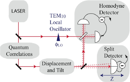
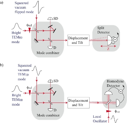
The purpose of this paper is to demonstrate the best possible measurements of beam displacement and tilt, for a given beam power and shape. Note that similar issues are addressed on the limits to the measurement of beam rotation about its propagation axis in reference Barnett . We will first focus on the detection device, and will therefore analyse experimentally a split-detection and a homodyne detection scheme with a TEM10 local oscillator (see Fig. 1), introduced theoretically in reference Hsu-disp . At the same time, we will present measurements of the quantum conjugated variable of the transverse displacement of the beam, the laser beam tilt Hsu-entang . Finally, we will focus on the laser beam itself, and show measurements beyond the fundamental limit imposed by the photon statistics of laser beams, using non classical beams. This demonstration allows displacement and tilt measurements that were masked or altered by quantum noise.
The paper is organized in the following way. We first give a brief definition of displacement and tilt of a TEM00 mode beam, and introduce the notions of position and momentum of a Gaussian beam, which are two conjugate transverse observables. In section II, we quantitatively discuss the QNL for displacement and tilt measurements and show the improvement that can be achieved with squeezed light. In section III, we present how this new set of quantum variables can be accessed with a split detection, the conventional scheme used for beam displacement measurements. The results obtained provide a reference for a homodyne detector with a TEM10 local oscillator presented in section IV. In section V, we show how to perform sub QNL measurements with both schemes and present experimental homodyne detection results in this regime. In the last section, a comparison between both schemes is presented, in perfect agreement with theoretical predictions, and showing an improvement with the homodyne detection that matches the predicted detection efficiency of .
I Displacement and tilt of a Gaussian beam
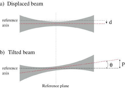
Displacement and tilt of a single-mode TEM00 laser beam are very intuitive notions, they refer to macroscopic properties of a beam, as shown in figure (2). We assume here that the beam is constrained to one dimension, namely the figure plane of the paper, considering that the non represented transverse component is gaussian. A displacement corresponds to a translation of the beam by a distance along the transverse direction, whereas a tilt corresponds to a rotation of the propagation axis by an angle . The tilt of a laser beam is linked to the transverse momentum of the beam, in the limit of small angles, given by the following expression
| (1) |
where is the optical wavelength. Note that displacement and tilt are defined relative to a particular transverse reference plane. For instance, in figure (2), we have chosen the beam waist plane as reference transverse plane.
In the case of small displacement and tilt, i.e. for and - where is the beam waist of the incident TEM00 mode, we can Taylor expand the displaced and tilted gaussian field to first order, yielding Hsu-disp ; Hsu-entang
| (2) | |||
| (3) |
The equations can be rewritten into
| (4) |
where refers to the Hermite Gauss mode Siegman . is the amplitude of the incident TEM00 mode and identifies with the one of the displaced and tilted beam at first order in and . Eq. (4) shows that the information of displacement and tilt of a TEM00 laser beam can be extracted by measuring the TEM10 mode component of the field. Any displacement modulation is transferred to the in-phase amplitude of the TEM10 mode relative to the ”carrier” (TEM00 mode), whereas any tilt modulation is transferred to the TEM10 component in quadrature relative to the TEM00 mode.
In order to give a quantum mechanical description of displacement and tilt of a laser beam, we need to take into account the quantum noise of all the optical modes of the beam, including the vacuum modes. We can write the positive frequency part of the electric field operator in terms of photon annihilation operators . The field operator is then given in its more general form by:
| (5) |
where is the field frequency, is the integration time, are the transverse beam amplitude functions of the TEMn0 modes, and are the corresponding annihilation operators. can be written in the form of , where describes the coherent amplitude and is the quantum noise operator assumed small in the linearization approximation.
For a mean photon number , defined by in the small displacement and tilt regime, the quantum counterpart of equation (4), assuming that only and are non-vacuum modes, is
| (6) | |||||
where we have introduced the mean value of position and momentum quantum operators of a laser beam, and , respectively. These quantum operators are given by
| (7) | |||||
| (8) |
where we see that position and momentum are linked to the amplitude and phase quadrature of the TEM10 mode component of the field, respectively given by
| (9) | |||
| (10) |
Moreover, position and momentum are conjugate observables and satisfy the following commutation relation Hsu-entang
| (11) |
In this section, we have defined displacement and tilt of a Gaussian beam, given the general quantum description of such a field, and shown that these former quantities were closely linked to position and momentum, two quantum observables. Using this interesting property, reference Hsu-entang already proposed a scheme for continuous variable spatial entanglement for bright optical beams, involving two beams respectively squeezed in position and momentum mixed on a beam-splitter.
II Quantum Noise Limit for Displacement and Tilt Measurements
The use of classical resources (i.e. coherent laser beams) sets a lower bound to detection performances, which is called the quantum noise limit (QNL) and arises from the random time arrival of photons on the detector. In the case of displacement measurement of a laser beam, the transverse displacement of a TEM00 laser beam corresponding to a Signal to Noise Ratio (SNR) of , is found to be fouet ; treps2
| (12) |
where is the waist of the beam, and its total number of photons detected in the interval , where is the resolution bandwidth. Ideally, is maximized according to the stability of the physical system. For instance in the case of bits read-out in optical disc devices, roughly corresponds to the scanning frequency. For a m waist, mW of power at a wavelength of m, with kHz, the quantum noise limit is for instance given by nm. Note that during test or characterization procedures, the precision can be increased by averaging with the spectrum analyzer, for instance by reducing the video bandwidth (VBW). The QNL effectively corresponds to the minimum measurable displacement when , without averaging.
Similarly, the QNL for momentum measurements can be defined as
| (13) |
In the same conditions as the ones defined above, the QNL for momentum measurement is m-1, corresponding to a tilt angle of rad.
In order to perform measurements beyond the QNL, i.e. for a given , we have shown in reference treps-multipixel that filling the appropriate transverse mode of the input field with squeezed light is a necessary and sufficient condition. We call this mode the noise-mode of detection Delaubert1 .
For example, using dB of squeezing in the appropriate component of the beam for a displacement measurement leads to a noise reduction of a factor 2. The SNR is quadratic in as the signal corresponds to the intensity of the TEM10 component of the displaced field, and the new quantum limit is thus given by . It is important to note that, as imposed by Heisenberg inequalities, the measurement of the conjugated observable - the momentum in this case - is degraded.
III Split detection
III.1 Theory
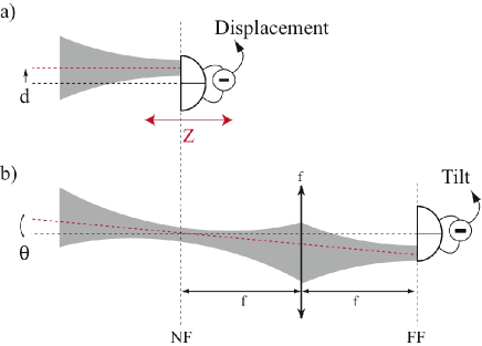
The conventional way to measure the displacement of a laser beam is to use a split detector. As shown in figure (3a), the difference between the intensity on each side of the split detector yields a photocurrent proportional to the displacement. This technique is widely used notably for beam alignments, particle tracking and atomic force microscopy. Nevertheless, such a detection device only accesses the beam position in the detector plane, and is totally insensitive to the orientation of the propagation axis of the beam (i.e. tilt). Consider the evolution of the field operator of Eq. 6 under propagation along the axis, we get
| (14) | |||||
where is the Hermite Gauss mode, is the Gouy phase shift, which equals , where is the Rayleigh range of the beam. The displacement and tilt ratio varies along because of the Gouy phase shift (i.e. diffraction), up to be perfectly inverted in the far field where . This Fourier Transform relation is a well known result in classical optics, for which a displacement in the focal plane of a simple lens is changed into an inclination relative to the propagation axis. Therefore, if the exact amount of tilt and displacement is needed in a particular transverse plane, for instance at , displacement can be measured in this plane (or in its near field), whereas tilt can only be accessed in its far field, as presented in figure (3b).
The field presented in Eq. 14 is detected via a split detector whose position is varied along the axis. The photocurrent is directly proportional to the difference of intensity incident on the two halves of the detector
| (15) | |||||
and replacing with the previous expression yields, for very small displacement and tilt
| (16) | |||||
where refers to the noise of the quadrature of the TEMn,0 mode defined by the angle , and
| (17) | |||||
where is the flipped mode, which is a TEM00 mode whose transverse profile has a phase shift at the origin for Delaubert-flipped . Its decomposition in the TEMpq basis during propagation is given by
| (18) |
and the fluctuations of its amplitude quadrature operator are found to be
| (19) |
where corresponds to the fluctuations of the amplitude quadrature of the mode .
Experimentally, we measure the displacement for different split detector positions. This displacement is induced by a modulating device generating at displacement and tilt modulations of amplitude and , respectively. A measurement at the modulation frequency, using a spectrum analyzer yields the modulation signal as well as the noise at this frequency. As usual in quantum optics, all equations are directly transposable into the frequency domain. Using Eq. 16, the variance measured by a spectrum analyzer at the precise modulation frequency is given by
| (20) |
where is a constant depending only on the electronic gains of the spectrum analyzer, is the integration time and . The first and second bracketed term in Eq. 20 respectively correspond to modulation signal and noise. In the plane of the modulating device (i.e. for ), the noise term can be written and corresponds to the noise of the amplitude quadrature of the flipped mode. The flipped mode is therefore the only mode contributing to the noise in this particular plane. Note that this is not true all along the propagation axis. For a coherent incoming beam, this noise term defines the shot noise level, and is equal to . Note that using non classical resources for which in the detection plane results in noise reduction. This case will be discussed in section V.
III.2 Experiment
We have performed split detection measurements of displacement and tilt of a Gaussian beam, by moving the position of the detector along the propagation axis, as shown in Fig. 4.
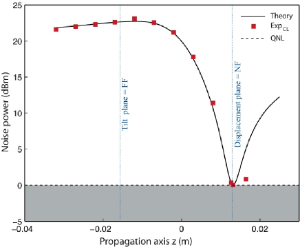
Displacement and tilt are produced by a piezoelectric element (PZT) modulated at MHz. Each measurement along the propagation axis refers to a different quadrature of the modulation (i.e. a different mixture of displacement and tilt modulation). The results are normalized to the shot noise and taken with a mW incident beam. From these measurements, we can infer the displacement and tilt relative amplitude modulation in the PZT plane where the waist is m. The displacement signal, accessible in the near field of the PZT, is found to be much smaller than the tilt signal, and even so that it cannot clearly be distinguished from the shot noise. This unusual behavior of the piezoelectric material arises from the operation regime, where the modulation is generated via an accidental mechanical resonance of the PZT. The theoretical curve has been plotted for a coherent illumination, using Eq. 20 for displacement modulation, and tilt modulation, ratio determined with the more accurate results presented in the section IV. There is a very good agreement with the experimental data. The last experimental point in Fig. 4 lies below the theoretical prediction, as the beam started to be apertured by the split detector, leading to a smaller measured modulation. Note that for technical reasons, our experimental setup is slightly different from the simplest setup presented on Fig. 3, where the reference plane coincides with the beam waist position. As shown on Fig. 4, the waist position lies at cm for the near field of the PZT in our imaging setup.
We have shown in this section how to retrieve displacement and tilt information from a gaussian beam with a split detector, and have taken experimental results which will be used as a reference in the following sections.
IV Homodyne detection with a TEM10 local oscillator
We have proved theoretically in reference Hsu-disp that split detection was non optimal to retrieve displacement information, as it is only sensitive to the flipped mode instead of the TEM10 mode component of the input field. In order to extract all the displacement and tilt information with up to efficiency, we propose a homodyne detector involving a TEM10 mode local oscillator, which selects the TEM10 mode component of the field.
In the homodyne detection scheme, two beams are mixed on a beam-splitter. The first one is the signal beam containing the displacement and tilt modulations, whose field operator is given by Eq. 6. The second one is the local oscillator (LO), whose field operator is
where denotes the number of photons per second in the beam, and is the local oscillator phase. Since displacement and tilt modulations are very small and the local oscillator is much brighter than the signal beam (i.e. ), the usual calculation of the intensity difference between the two homodyne detectors at the modulation frequency gives
| (21) | |||||
and similarly to Eq. 20, its variance at the displacement and tilt modulation frequency is therefore
| (22) |
where the constant is identical to the split detection part as long as the spectrum analyzer settings have not been changed. The first bracketed term corresponds to the modulation signal. The second one refers to the noise of the TEM10 component of the detected field, and its variation with the local oscillator phase is given by , where and are the noise of the amplitude and phase quadrature of the TEM10 mode, respectively. Scanning the local oscillator phase allows to measure all the quadratures of the displacement and tilt modulation. We have omitted the Gouy phase shift in the previous expression, as it can be incorporated as a constant term in the local oscillator phase. This phase is still defined so that corresponds to a displacement measurement in the PZT plane.
Only the TEM10 mode of the incoming beam contributes to the noise, as it matches the local oscillator transverse shape. All the other modes contributions cancel out since they are orthogonal to the local oscillator. The TEM10 mode is thus the noise mode of the homodyne detection, and precisely matches the information to be extracted. We can show, using a Cramer Rao bound estimation, that the TEM10 homodyne detection is an optimal displacement and tilt detection, as no other device can possibly perform such measurements with a better SNR CRB .
For a coherent incoming TEM10 mode, the previous noise term defines the shot noise level, and is equal to . Using squeezed light in the TEM10 mode component of the incoming beam would result in noise reduction, and will be discussed in the section V.
The SNR for a coherent incoming beam can be derived from Eq. 22 in the homodyne detection case
| (23) |
Comparing the split and homodyne detections schemes yields certain similarities between Eq.(20) and (22). First, a variation of the local oscillator phase in the homodyne scheme is equivalent to a propagation along the axis inducing a Gouy phase shift in the split detection case. Secondly, an additional geometry factor in the split detection case arises from the imperfect overlap between the flipped mode and the TEM10 mode, as discussed in reference Hsu-disp . The comparison between the two SNRs in the coherent case yields a theoretical efficiency ratio given by
| (24) |
where and refer to the number of photon per second in the displaced and tilted beam, for the split detection and the homodyne detection case, respectively. For identical signal beams powers, this means that the split detection is only efficient compared to the homodyne detection. Using the homodyne detection thus corresponds to an improvement of .
Eventually, the intensity factor before the bracketed term in Eq. 22 and Eq. 20 can be much bigger in the homodyne detection case, as it corresponds to the local oscillator intensity instead of the input beam intensity in the split detection case. It is thus easier to have more electronic noise clearance in the homodyne case.
In this section, we have shown - still theoretically - how to retrieve displacement and tilt using a homodyne detector with a TEM10 local oscillator. Moreover, we have proved a theoretical improvement of this scheme compared to the split detection.
V Displacement and Tilt Measurements beyond the Quantum Noise Limit
When the information to be retrieved is below - or of the order of - the quantum noise, non classical resources (i.e. squeezed laser beams) can help extracting the information. For each type of detection (i.e homodyne- and split detection), the only transverse mode component within the incident field which contributes to the noise has been identified in the previous sections. The noise modes of the split and homodyne detection are the flipped mode and the TEM10 mode, respectively. Since displacement and tilt of a TEM00 beam lies in the TEM10 component of the beam, noise mode and information encoded are matched for the homodyne detection only, accounting for the non optimal split detection.
Sub shot noise measurements with both schemes can be performed using the setups shown in Fig. 5, by filling the noise mode of the input beam with squeezed light. A mode combiner has to be used to merge the signal beam - in our case a bright TEM00 beam - with the noise mode of detection, filled with squeezed vacuum. Note that it has to be a vacuum mode, or a very dim field not to contribute to the signal, but only to reduce the quantum noise properties. The combination of beams cannot be done with a sheer beam-splitter as the squeezing is not robust to losses. Instead, we used a special Mach-Zehnder interferometer with an additional mirror in one arm, see (Fig. 5). This mirror has no effect on even transverse profiles, but induces an additional phase shift to odd transverse profiles. Therefore, thanks to this asymmetry, orthogonal even and odd modes, which are incident on the two input ports of the Mach-Zehnder, interfere constructively on the same output port without experiencing any losses. The integrality of the bright beam and the squeezing of the squeezed vacuum mode - a) flipped mode or b) TEM10 mode - are thus preserved at the output of the interferometer. Note that other devices can be used treps1d ; treps2d ; treps2 .
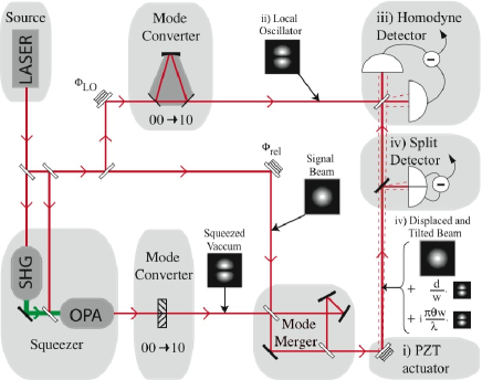
In order to make a direct comparison of the performances of the split detection and the homodyne detection, we have built the experimental setup sketched in Fig. 6, where both schemes are tested in the same operating conditions. In addition to a simple comparison involving only classical resources, we designed the experience in order to allow measurements beyond the QNL. At this stage, we were unable to produce directly a squeezed TEM10 mode, we have therefore chosen to generate a squeezed flipped mode, which also corresponds to a squeezed TEM10 mode having experienced losses.
Indeed, the amount of squeezing in the amplitude quadrature of the TEM10 component of the flipped mode can be deduced from
| (25) |
as all the modes except the flipped mode are filled with coherent light. If the flipped mode is a classical coherent beam, , which also implies that the TEM10 component is coherent , as expected. In the end, if we start with dB of squeezing in the amplitude quadrature of the flipped mode as discussed below, we get dB of squeezing in the TEM10 mode, which is exactly what can be measured experimentally by using the homodyne detection with a TEM10 local oscillator.
We used the following experimental procedure. First we generated a dB squeezed TEM00 mode from a monolithic optical parametric amplifier (OPA) pumped by a frequency doubled YAG laser delivering mW at nm, and seeded by a TEM00 mode. This very low power (nW) squeezed beam then experiences a mode conversion into the flipped mode thanks to a special wave-plate made of two half wave-plates whose optical axis have been rotated relative to each other Delaubert-flipped . A beam incident on such an optical element yields a phase shift on half of its transverse profile.
Thanks to the special Mach-Zehnder interferometer formerly presented, we combine this beam with a bright TEM00 beam, therefore preserving their potential non classical properties. To achieve this experimentally, we first mode matched both input beams of the interferometer without the special wave-plate, reaching visibility on the first beam-splitter of the interferometer. The squeezed beam, although very dim, is still bright enough to be mode matched with the other bright TEM00 beam. The interferometer is then aligned on the OPA beam without the wave-plate with visibility and then the wave-plate is slid in the center of the beam to a maximum visibility of . Note that we purposely introduced a leakage in one of the mirrors to lock the relative phase between the two input modes with a split detector (SD), as drawn in Fig. 5). In the end, the global mode combiner efficiency is still higher than .
The multi-mode squeezed beam hereby generated is then displaced and tilted with a PZT, as presented in section III, and the information is detected with either one of the split or homodyne detection schemes. We only presented classical measurements for the split detection case in Fig. 4, as such measurements have already been demonstrated. Moreover, the measurements have to be done precisely in the near field of the mode converting wave-plate - which is also the near field of the PZT - as the flipped mode is not stable in propagation, and squeezing degrades very quickly along the direction.
The TEM10 local oscillator is produced with a misaligned ring cavity locked to resonance on the TEM10 mode represented in Fig. 6. The cavity has been designed such that it delivers a pure transverse output mode (i.e. high order modes are not simultaneously resonant in the cavity). We mode matched this local oscillator beam to the signal beam by previously locking the ring cavity to the TEM00 mode resonance, reaching a visibility of with the TEM00 input mode.
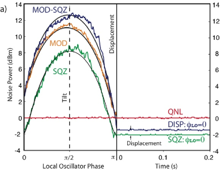
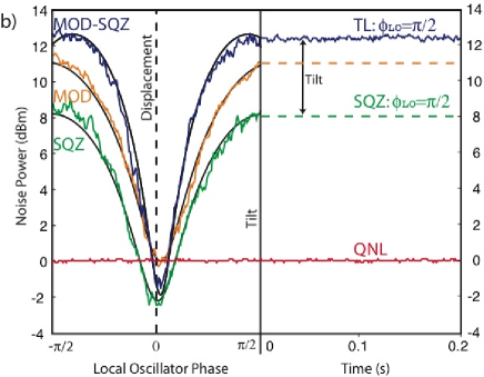
The experimental results, obtained with the spectrum analyzer in zero-span mode at 4 MHz, are presented in Fig. 7(a) and Fig. 7(b), when the TEM10 local oscillator phase is scanned and locked for displacement () and tilt () measurement. Without the use of squeezed light, the displacement modulation cannot clearly be resolved, as in the split detection case. Improvement of the SNR for displacement measurement beyond the quantum noise limit is achieved when the squeezed quadrature of the TEM10 mode is in phase with the displacement measurement quadrature (i.e. in phase with the incoming TEM00 mode). Since we are dealing with conjugate variables, improving the displacement measurement degrades the tilt measurement of the same beam, as required by the anti-squeezing of the other quadrature. The displacement measurement is improved by the 2 dB of squeezing, whereas the tilt measurement is degraded by the 8 dB of anti-squeezing. Theoretical curves calculated with dB of noise reduction and 8 dB of anti-squeezing, and of tilt modulation and of displacement modulation - continuous curves in Fig. 7(a) - are in very good agreement with experimental data. In our experiment, we have a TEM00 waist size of m in the PZT plane, a power of W, kHz and Hz, corresponding to a QNL of nm. The measured displacement lies 0.5 dB above the squeezed noise floor, yielding a displacement modulation 0.08 times larger than the QNL. As the modulation has a square dependance on the displacement , we get nm. This would correspond to a trace 0.3 dB above the QNL, and cannot therefore be clearly resolved without squeezed light. The ratio between displacement and tilt modulations can be inferred from the theoretical fit in figure 7, giving a measured tilt of rad.
We have in this section demonstrated measurements of a pair of quantum conjugate variables - displacement and tilt - with a homodyne detector involving a TEM10 mode local oscillator, and performed sub shot noise displacement measurements.
VI Comparison
We can compare the results obtained with the split detection and the homodyne detection by using Eq. 24, where we need to take into account the input beam power discrepancy between both experiments. It was necessary to take data with more power in the modulated beam for the split detection in order to have a sufficient noise clearance between the electronic noise and the shot noise. As for the homodyne detection, the local oscillator can be intense, and the noise clearance above the electronic noise can reach around 10 dB. This is interesting when the signal to be retrieved is very small, but can on the other hand also be a limitation for large signals. The experimental efficiency ratio can be evaluated with the following expression
| (26) |
where W and mW refer to the signal beam powers, in the case of the homodyne and split detection, respectively. and are the maximum detected modulation in each detection scheme, relative to the shot noise. The two experimental curves read dB and dB, which yields , and which precisely correspond to the theoretical expectation. The uncertainty, mainly given by the one on the maximum modulation values, can be evaluated to . We therefore report an efficiency improvement of in perfect agreement with the theoretical value calculated in reference Hsu-disp .
Although the split detection is easier to set-up experimentally,
the homodyne scheme is more efficient and allows measurements of
both the displacement and tilt of the beam without moving the
detector position, giving a complete information on the
interaction between the sample and the beam. We show that one can
choose which measurement to improve (tilt or displacement) using
squeezed light by simply varying the phase of the squeezed beam.
There are additional limitations to the use of a split detector
due to its gap and to its finite size, which are imposing
constraints when the variation of the modulation on the
propagation axis is measured. The accessible range to a good
detection on the axis is small, as the beam can neither be too
small (because of the gap), nor too large (because of the finite
size of the detector). Moreover, in order to perform measurements
beyond the QNL, one has to carefully image the squeezed flipped
mode onto the sample, and also onto the detector, as the flipped
mode is not stable in propagation. This imaging difficulty is not
present in the homodyne case. Nevertheless, it is replaced with
the constraint of a careful mode matching of the incoming beams.
Moreover, homodyne detection cannot be used for the positioning of
an incoherent light beam, as it is relying on the interferences
between incoming beam and local oscillator.
Conclusion
We have demonstrated a homodyne detection scheme involving a TEM10mode local oscillator in order to measure the displacement and tilt of a Gaussian beam. We report a detection efficiency improvement of relative to the split detection, in perfect agreement with the theoretical value. Our detection setup is very simple and could thus easily replace split and quadrant detectors in many applications, particularly when tilt and displacement are needed at the same time. Moreover, further developments using non classical are possible, as we have presented measurements beyond the QNL with these devices. Note that we are now able to generate the squeezed TEM10 mode directly, without the use of a wave-plate, with a misaligned Optical Parametric Amplifier NaturePhys , allowing a simplification of the setup.
Quantum measurements in the transverse plane such as the ones presented in this paper potentially open the way to parallel quantum information processing. Indeed, instead of using amplitude and phase quadratures or Stokes operators, conjugated quantum operators are now available in the transverse plane. The generation of spatial-entanglement between position and momentum of two laser beams will be considered as a first step towards this goal. Note that spatial entanglement has already been demonstrated with orbital angular momentum in the single photon regime Woerdman1 ; Woerdman2 . Other types of experiments that could follow are dense coding and teleportation of spatial information and spatial holography.
VII Acknowledgements
We like to thank Magnus Hsu, Warwick Bowen and Nicolai Grosse for helpful discussions. This work was supported with funding from the Australian Research Council Centre of Excellence program. P.K.Lam and H-A.Bachor enjoy funding as ARC fellows.
References
- (1) M. T. L. Hsu, V. Delaubert, P. K. Lam and W. P. Bowen, J. Opt. B : Qu. Semiclass. Opt. 6, 495 (2004).
- (2) E. Morrison, B. J. Meers, D. I. Robertson and H. Ward, Appl. Opt. 33, 5041 and 5049 (1994)
- (3) J. H. Chow, G. de Vine, M. B. Gray, and D. E. McClelland, Opt. Let. 20, 2339 (2004)
- (4) see also references in Hsu-disp
- (5) S. M. Barnett and R. Zambrini, J. Mod. Opt. 53, 613 (2006).
- (6) M. T. L. Hsu, W. P. Bowen, N. Treps and P. K. Lam, Phys. Rev. A 72, 013802 (2005).
- (7) A. E. Siegman, Lasers, Mill Valley, CA: University Science (1986)
- (8) C. Fabre, J. B. Fouet, et A. Maître, Opt. Let. 25, 76 (2000).
- (9) N. Treps, N. Grosse, W. P. Bowen, M. T. L. Hsu, A. Maître, C. Fabre, H-A. Bachor, P. K. Lam , J. Opt. B 6, S664 (2004).
- (10) N. Treps, V. Delaubert, A. Maître, J. M. Courty and C. Fabre, Phys. Rev. A 71, 013820 (2005).
- (11) V. Delaubert, N. Treps, C. C. Harb, P. K. Lam and H-A. Bachor, Opt. Let., 31, 1537 (2006).
- (12) V. Delaubert, N. Treps, P. Réfrégier, H-A. Bachor and C. Fabre, to be submitted.
- (13) V. Delaubert, D. A. Shaddock, P. K. Lam, B. C. Buchler, H-A. Bachor and D. E. McClelland, J. Opt. A 4, 393 (2002).
- (14) N. Treps, U. Andersen, B. Buchler, P.K. Lam, A. Maître, H. Bachor, C. Fabre, Phys. Rev. Let. 88 203601 (2002)
- (15) N. Treps, N. Grosse, W. P. Bowen, C. Fabre, H.-A. Bachor and P. K. Lam, Science, 301, 940 (2003).
- (16) M. Lassen, V. Delaubert, C. C. Harb, P. K. Lam, N. Treps and H-A Bachor, J. Eur. Opt. Soc., 1, 06003 (2006).
- (17) S. S. R. Oemrawsingh, X. Ma, D. Voigt, A. Aiello, E. R. Eliel, G. W. ’t Hooft, and J. P. Woerdman Phys. Rev. Lett. 95, 240501 (2005).
- (18) S. S. R. Oemrawsingh, J. A. de Jong, X. Ma, A. Aiello, E. R. Eliel, G. W. ’t Hooft, and J. P. Woerdman Phys. Rev. A 73, 032339 (2006).