Linear optics quantum Toffoli and Fredkin gates
Abstract
We design linear optics multiqubit quantum logic gates. We assume the traditional encoding of a qubit onto state of a single photon in two modes (e.g. spatial or polarization). We suggest schemes allowing direct probabilistic realization of the fundamental Toffoli and Fredkin gates without resorting to a sequence of single- and two-qubit gates. This yields more compact schemes and potentially reduces the number of ancilla photons. The proposed setups involve passive linear optics, sources of auxiliary single photons or maximally entangled pairs of photons, and single-photon detectors. In particular, we propose an interferometric implementation of the Toffoli gate in the coincidence basis, which does not require any ancilla photons and is experimentally feasible with current technology.
pacs:
03.67.-a, 03.67.Lx, 42.65.LmI Introduction
Quantum information theory Nielsen00 exploits the laws of quantum mechanics to devise novel methods of information processing and transmission that would be impossible or very hard to achieve classically. During recent years various protocols for quantum information processing were successfully demonstrated experimentally with several different physical systems. Particular attention has been paid to optical realizations where the quantum bits are encoded onto states of single photons. Photons are ideal carriers of quantum information because they can be distributed over long distances in low-loss optical fibers or in free space. While perfect for quantum communication purposes, photons seemed to be less suitable for quantum computing because the lack of sufficiently strong optical nonlinearities seemed to prevent the implementation of quantum gates between photons.
The situation changed radically in 2001 when Knill, Laflamme, and Milburn (KLM) published their landmark paper in which they showed that a scalable universal quantum computation is possible with only single photon sources, passive linear optical interferometers and single photon detectors Knill01 . The key insight of KLM is that the nonlinearity (such as a Kerr effect) can be simulated on a single-photon level using the above listed resources, conditioning on particular measurement outcomes of the detectors and applying appropriate feedback. The resulting linear optics quantum gates Kok05 are generally only probabilistic but the probability of success could be in principle made arbitrary close to unity by exploiting off-line generated multi-photon entangled states and quantum teleportation Bennett93 ; Bouwmeester97 ; Boschi97 .
The KLM paper stimulated a number of further works suggesting alternative and improved constructions of the basic quantum C-NOT gate Ralph01 ; Pittman01 ; Knill02 ; Hofmann02b ; Franson02 ; Zou02b whose experimental demonstrations by several groups followed Pittman02 ; Pittman03 ; Brien03 ; Sanaka04 ; Gasparoni04 ; Zhao05 ; Langford05 ; Kiesel05 ; Okamoto05 . However, despite these promising successes, extending this approach to more complex schemes involving higher number of photons currently appears to be a formidable experimental task because the overhead in resources (in particular the number of ancilla photons) required by the original KLM scheme is very high.
It is possible to combine the ideas of one-way quantum computation Raussendorf01 ; Raussendorf03 and linear optics quantum computing to significantly reduce the resources required for the computation. The techniques introduced by KLM could be used to generate a multiphoton cluster state which then serves as a resource for quantum computing which proceeds by performing certain carefully chosen measurements on each photon from the cluster Yoran03 ; Nielsen04 ; Browne05 ; Gilbert05 . First proof-of-principle experimental demonstration of one-way quantum computation with four-photon cluster state has been reported recently Walther05b .
In this paper, we wish to address a different aspect of the quantum computing with linear optics. Namely, we will be interested in the implementations of the fundamental Toffoli and Fredkin gate which play an important role both in classical (reversible) computing and in quantum computing and information processing Nielsen00 . In the universal quantum computer the multi-qubit gates are usually assumed to be implemented as a sequence of single and two-qubit gates. However, this strategy may not be optimal in the context of linear optics quantum computing, where schemes tailored specifically for multiqubit gates may require less ancilla photons or achieve higher probability of success than implementations relying on a sequence of the single and two-qubit gates.
The rest of the paper is organized as follows. In Section II we will present a scheme for the -qubit generalized Toffoli gate, which flips the state of the th qubit in the computational basis if all the control qubits are in state , where tilde indicates the logical qubit states throughout the paper to distinguish them from the Fock states . We will first design gate operating in the so-called coincidence basis Ralph02 , which has the advantage that this scheme does not require any ancilla photons. To make this gate non-destructive it is necessary to perform quantum non-demolition measurement of number of photons at the output of the gate, which could be done with linear optics, ancilla photons and photon-number resolving detectors Kok02 . Section III is devoted to the three-qubit Fredkin gate which is a controlled SWAP gate, the states of the two target qubits are swapped if the control qubit is in state . Our scheme requires only six ancilla photons. Finally, Section IV contains brief conclusions and summary of the main results.
II Quantum Toffoli gate with linear optics
In this section we will present and analyze the scheme which realizes quantum -qubit Toffoli gate in the coincidence basis. More precisely, the scheme conditionally applies the -qubit controlled phase gate to the input qubits, whereby the phase changes by if all qubits are in the state and does not change otherwise,
| (1) |
where and . Note that the N-qubit controlled-phase (C-phase) gate and the Toffoli gate are equivalent up to single-qubit Hadamard transformations on the th qubit (the target), .
II.1 Quantum optical C-phase gate
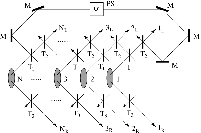
The proposed optical setup is schematically sketched in Fig. 1. The qubits are encoded into states of single photons. We assume the dual-rail encoding where the two logical levels and correspond to two paths and taken by a photon, and . Note that other encodings such as polarization or time-bin are also possible and can be mutually converted into each other by means of polarizing beam splitters and unbalanced interferometers.
The operation of the C-phase gate requires that the phase of the -photon state changes by if and only if all photons are in the modes. In the proposed scheme this is achieved by the -photon interference on an array of unbalanced beam splitters, see Fig. 1. First, each photon propagating in the mode is split into two modes on a beam splitter with intensity transmittance . Then pairs of beams originating from modes and interfere on an array of beam splitters with transmittance . Each mode passes through a beam splitter with transmittance which acts as a filter balancing the amplitudes of the modes and after the application of the gate.
The gate operates in the coincidence basis, i.e. it succeeds if a single photon is detected in each pair of the output modes and . Assume first that at least one photon is in mode . It is easy to see that in this case the only way how the photons in the modes can reach the appropriate output ports of the beam splitters is that each photon is transmitted through both beam splitters and the total probability amplitude of this to happen reads , where is the number of photons in modes and is the amplitude transmittance, . Since the gate should be unitary, must not depend on which can be achieved by choosing
| (2) |
The situation changes when all photons are initially in modes, i.e. the input state reads . In this case, there are two ways how the photons can reach the output ports. One option is that all photons are transmitted through all beam splitters. The second option is is that all photons are reflected from all beam splitters. Provided that these two alternatives are indistinguishable, i.e. there is a good spatiotemporal overlap of the photonic wavepackets on the beam splitters, they interfere, and the resulting amplitude reads,
| (3) |
Note the minus sign which arises due to the phase shift in one path of the reflected photon, see Fig. 1. Note also that in the figure the path of the reflected photon in mode looks much longer than all other paths. In the actual implementation the geometry of the setup should be such that all paths would be carefully balanced resulting in a good overlap of the photons and high-visibility interference.
The gate operates as desired if . Expressed in terms of the intensity transmittances this condition translates into
| (4) |
where we used that . The formula (4) describes a single-parametric class of the N-qubit optical controlled-phase gates working in the coincidence basis. The probability of success is given by and on expressing in terms of from Eq. (4),
| (5) |
we obtain
| (6) |
The optimal maximizing can be easily determined by solving , which yields
| (7) |
On inserting this value into Eq. (5) we find that hence it is optimal to use a scheme where the transmittances and are the same. The optimal probability then reads,
| (8) |
In particular, for we find %.
II.2 Generalized C-phase gate
The transformation (1) can be extended such that an arbitrary phase shift is introduced when all qubits are in logical state . The generalized controlled-phase gate thus acts as follows,
| (9) |
We shall show that also this operation can be conditionally implemented with the scheme shown in Fig. 1 provided that the phase shift in one arm of the multiphoton interferometer and the transmittances and are properly chosen. Repeating the derivation outlined in the preceding subsection we find that the condition that has to be satisfied reads
| (10) |
Upon splitting this formula into the real and imaginary parts and solving for we obtain
| (11) |
Similarly we also arrive at a generalization of the formula (4),
| (12) |
The probability of success is maximized by choosing
| (13) |
and we have . Note that the probability of success depends on the required conditional phase shift and for a fixed it achieves its minimum for , i.e. when we attempt to implement the N-qubit Toffoli gate.
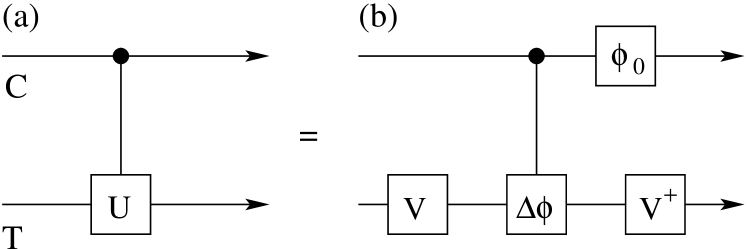
With the two-qubit generalized C-phase gate at hand we can implement in the coincidence basis an arbitrary two-qubit controlled- gate, where a unitary operation is applied to the target qubit iff the control qubit is in state . The equivalent scheme involving C-phase gate is shown in Fig. 2(b). Note first that in the basis of eigenstates of , the controlled unitary gate boils down to conditional phase shifts,
| (14) |
The unitary maps the eigenstates of onto the computational basis states, , . Next a C-phase gate with follows. Finally, the inverse operation is applied to the target while the control qubit is subject to a phase shift operation , . It is easy to see that the net result of this sequence of gates is the controlled- operation (14).
II.3 Heralded controlled-phase gate
The advantage of working in the coincidence basis is that no extra ancillary photons are required. The scheme is thus very economical in resources and for instance the demonstration of the three-qubit Toffoli gate would require detection of three-photon coincidences which is well within the scope of present technology.
However, this approach also suffers from a significant disadvantage, since we do not know whether the gate succeeded until we detect the photons. It is thus not possible to directly employ this gate as a part of a more complex quantum information processing network. Nevertheless, it is possible to remove this drawback by performing quantum non-demolition measurements of the number of photons at the outputs of the gate. If this measurement verifies that a single photon is present in each pair of modes and then we know that the gate was applied successfully while the non-demolition character of this measurement guarantees that the output photons emerging from the gate are preserved and not destroyed by the verification.
A simple way of performing the non-demolition measurement of a number of photons in two modes is to employ an auxiliary pair of photons in a maximally entangled state and attempt to teleport the single photon in modes and Kok02 . The single-photon detectors used for the partial Bell measurement which lies at the heart of the teleportation Bouwmeester97 must be able to resolve the number of photons. Detection of exactly two photons in the Bell analysis confirms that a single photon has been successfully teleported. Observation of any other total number of photons indicates a failure of the gate. This method requires auxiliary maximally entangled photon pairs in total and the probability of successful non-demolition measurement given that the gate was applied successfully scales as because the optimal partial Bell measurement with linear optics can distinguish only two out of four Bell states.
An alternative scheme for partial probabilistic non-demolition photon number measurement on a pair of modes has been proposed in Kok02 (see also discussion in Ref. Fiurasek03 ). The advantage of this latter scheme is that it does not rely on maximally entangled photon pairs and instead requires single photons in product state, which may be easier to generate. The measurement requires two ancilla photons and two photodetectors which can distinguish the number of photons in a mode. A coincidence detection of a single photon by each detector indicates that at least a single photon has been present in the input pair of modes and if exactly a single photon was at the input then its state was not disturbed by the measurement. If this partial measurement is carried out on each pair of modes and if all measurements indicate that there was at least a single photon in each pair of modes then since there were altogether photons at the input of the gate we can conclude that the C-phase gate was applied successfully.
III Fredkin gate
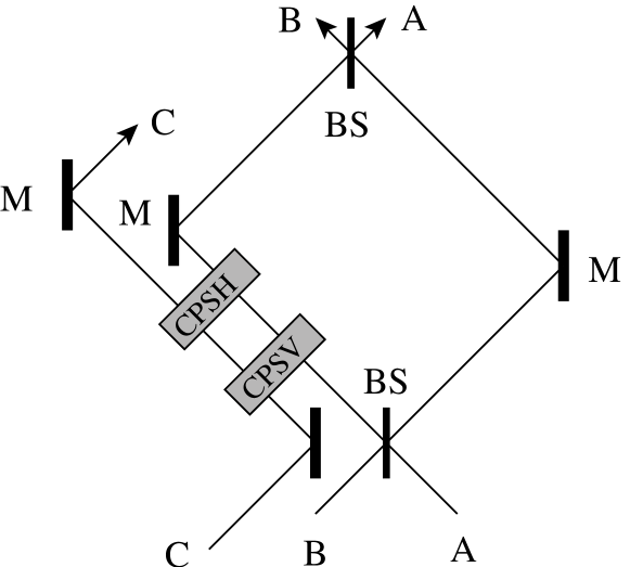
Our scheme for linear optics Fredkin gate is inspired by the quantum optical Fredkin gate originally proposed by Milburn Milburn89 . The Fredkin gate is a controlled SWAP operating on the Hilbert space of three qubits, the states of qubits and are exchanged if the control qubit is in state and nothing happens if it is in state . Let us assume that the qubits are encoded onto polarization states of single photons. The controlled SWAP operation can be converted to the controlled phase shift with the use of a balanced Mach-Zehnder interferometer, see Fig. 3. Depending on the state of the control photon , the phase shift in the left arm of the interferometer should be either or , the latter results in the effective swap of the photons and at the output of the interferometer. In Milburn’s scheme, the controlled phase shift is achieved by medium with cross Kerr nonlinearity.
In the spirit of linear optics quantum computing, we suggest to replace the Kerr medium with a linear interferometric scheme, and employ ancilla photons and postselection conditioned on single photon detection to simulate the required cross Kerr interaction Clausen03 . Since we assume polarization encoding, the conditional phase shift has to be applied to both vertically and horizontally polarized modes in the left arm of the Mach-Zehnder interferometer in Fig. 3. In what follows we will describe a scheme which provides this conditional phase shift for a single mode, and the linear optics Fredkin gate then involves two such basic blocks acting in series on vertically and horizontally polarized mode, see Fig. 3.
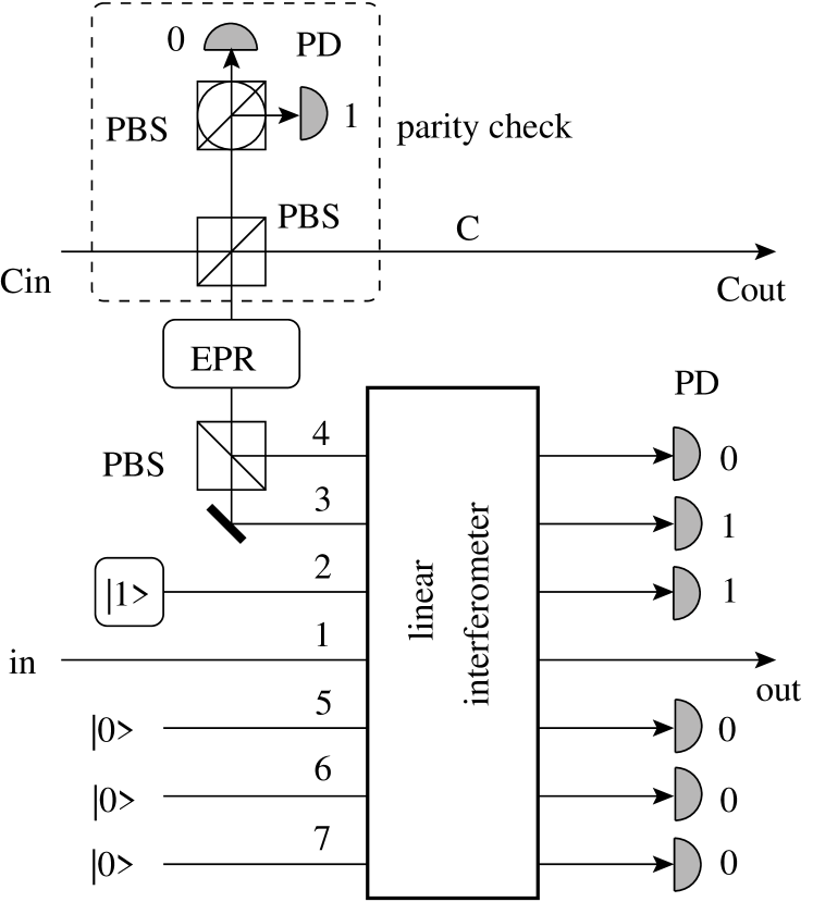
The basic block is depicted in detail in Fig. 4. The scheme requires three ancilla photons: a maximally entangled pair of photons in a state emitted by source (EPR) and an additional single photon in mode . The proposed setup consists of two main parts. The first part is the quantum parity check Pittman01 ; Pittman02 between the control photon in mode and one photon from the auxiliary EPR beam. The check is based on a coupling of these photons on a polarizing beam splitter PBS followed by a detection of one of the outputs in the basis . The detectors should be able to resolve the number of photons in the beam and the parity check is successful if a single photon is detected by one detector and no photon is detected by the other detector, which happens with probability . The parity check effectively copies in the computational basis the state of the control photon in spatial mode onto the auxiliary photon in spatial modes and and we can write,
| (15) |
The parity check allows us to control the phase shift of mode indirectly by the auxiliary photon while preserving the original control photon. A similar trick has been used in the recent experimental implementations of quantum C-NOT gate Pittman03 ; Gasparoni04 ; Zhao05 .
The second part of the scheme in Fig. 4 consists of a linear interferometer where the photons in the mode are combined with the ancilla photons in modes , and . Note that the interferometer has also three other auxiliary input ports in vacuum state. All output modes of the interferometer except for mode are monitored with photon number resolving detectors and the conditional phase shift is successfully applied if a single photon is detected in modes and and no photons are observed in the other modes.
The purpose of the interferometer is to conditionally induce a phase shift in mode provided that there is a photon in the input mode and induce no shift if the photon is in mode . Since there can be no more than photons in the mode (the two photons whose polarization states should be conditionally swapped), it suffices to achieve the correct conditional phase shift in the subspace of Fock states , and .
Mathematically, the interferometer is described by a unitary matrix , which governs the transformation between input and output modes. The input creation operators can be expressed as linear superpositions of the output creation operators according to
| (16) |
where are the elements of . Since we condition on observing no photons in modes -, in our subsequent calculations we will explicitly need only the coefficients with and .
Due to the linearity we can treat separately the cases when the control photon is in state and . Assume first that it is in state . The two auxiliary photons are then in input modes and and conditionally on detecting a single photon in the output modes and and no photon is all other modes (except for mode which is not measured upon), we obtain the following transformation,
| (17) |
where the coefficients can be expressed as follows,
| (18) |
If the control photon is in state , then the conditional transformation reads
| (19) |
where the coefficients can be expressed in the same way as , only the matrix elements in Eq. (18) must be replaced with .
We want to implement a conditional -phase shift in mode . This will be achieved if
| (20) |
where is some shrinking factor arising due to the probabilistic nature of the gate. Low reduces the probability of success of the gate which scales as but does not alter its operation. The maximum that can be chosen is determined by the constraint that (, ) must form a submatrix of a unitary matrix. As shown in the Appendix, it is possible to efficiently numerically determine whether a given set of may form a submatrix of so that also the maximum can be determined numerically.
By solving the system of nonlinear equations (20) we can find the matrix elements specifying the interferometer which implements the conditional phase shift. Note that the system is underdetermined hence there exist infinitely many interferometers satisfying (20). To see this, it is convenient to rewrite these equations in a matrix form,
| (21) |
where and are column vectors and is a matrix whose elements can be expressed in terms of and . Thus when looking for the solution to Eqs. (21) we can choose arbitrary and and provided that we can for a given calculate and by solving the system of linear equations (21).
Let us now present a particular example of an analytical solution. Choosing
| (22) |
we can express the matrix elements as follows,
| (23) |
Similar formulas hold also for and we have,
| (24) |
The maximum achievable within the above given analytical solution was determined numerically and we found that it is optimum to choose and yielding . Since the Fredkin gate in Fig. 3 includes two conditional phase shift gates, the total probability of success of the gate is given by where the factor appears due to the two quantum parity checks. On inserting the into this formula we obtain , which is rather small. However, it should be stressed that this is not the maximum probability of success that could be attained with our scheme. It is possible to improve the success rate by several orders of magnitude by performing numerical optimization over all relevant parameters and . We have carried out a thorough numerical search and the maximum that we obtained in this way reads .
In is instructive to compare this value with the probability of success that could be achieved if one would attempt to implement the Fredkin gate as a sequence of two-qubit unitaries. It was shown by Smolin and DiVincenzo that five two-qubit quantum gates suffice to implement the Fredkin gate Smolin96 . Making the very optimistic assumption that using two ancilla photons per gate each of these gates can be implemented with probability similarly as the C-NOT Gasparoni04 ; Zhao05 we arrive at a total probability . Thus our scheme for Fredkin gate could potentially attain a higher probability of success while being more economical in resources because it requires only ancilla photons instead of photons.
IV Conclusions
We have devised schemes for linear optics quantum Toffoli and Fredkin gates. In the spirit of linear optics quantum computing the gates do not require nonlinear interaction and instead rely on multiphoton interference, ancilla photons and postselection conditioned on single-photon detection. The key feature of the proposed setups is that they are directly tailored for the implementation of the multiqubit Toffoli or Fredkin gate. This should be contrasted with the common approaches where the multiqubit gates are decomposed into a sequence of two- and single-qubit gates.
Given the current state of the technology, our direct approach to multiqubit gates may be much more efficient than implementations relying on a sequence of two-qubit gates. In particular, the experimental demonstration of the three-qubit quantum Toffoli gate in the coincidence basis would require only three photons and an observation of a three-photon coincidences, which is well within the reach of current technology.
Despite their advantages, the present schemes still suffer from some weaknesses. The probability of success of the N-qubit Toffoli gate exponentially decreases with growing and also the probability of success of the Fredkin gate, , is not very high. Another drawback lies in the fact that setups for both Toffoli and Fredkin gate require interferometric stability, which is hard to achieve and maintain. In contrast, recent experimental demonstrations of the quantum linear-optical C-NOT gate relied solely on Hong-Ou-Mandel interference effect Langford05 ; Kiesel05 ; Okamoto05 , which is much more robust against small length fluctuations.
It remains an interesting open question whether a scheme avoiding problems with interferometric stability could be devised also for the Toffoli and Fredkin gates. Another important open issue is what is the maximum achievable success rate for these gates either without ancillas (i.e. operating in the coincidence basis) or with a given fixed amount of auxiliary photons. We hope that the present paper will stimulate further theoretical as well as experimental investigations along these lines potentially resulting in an important step towards linear optics quantum computing.
Acknowledgements.
The author would like to thank L. Mišta for helpful discussions and comments. This work was supported under the Research project Measurement and Information in Optics MSM 6198959213 of the Czech Ministry of Education.*
Appendix A Testing the unitarity
Here we show how to test whether a matrix , , , could be a submatrix of a larger unitary matrix . The procedure consists of two steps which have to be repeated for each . We start from .
Step (i): We set for . We can assume without loss of generality that is real and nonnegative and determine it from the normalization condition ,
If this expression yields purely imaginary then could not form a part of a unitary matrix and we terminate the test.
Step (ii): We must guarantee that the rows of are mutually orthogonal. This can be achieved by calculating from the orthogonality condition
For all satisfying we thus have
Finally, we increase by .
The steps (i) and (ii) have to be repeated until is reached. If all four iterations succeed then at the end we obtain a isometry matrix that could be easily completed to form a unitary matrix. Otherwise we know from step (i) that the matrix could not form a submatrix of a unitary matrix.
References
- (1) M.A. Nielsen and I.L. Chuang, Quantum Computation and Quantum Information (Cambridge University Press, Cambridge, 2000).
- (2) E. Knill, R. Laflamme, and G.J. Milburn, Nature (London) 409, 46 (2001).
- (3) P. Kok, W.J. Munro, K. Nemoto, T.C. Ralph, J. P. Dowling, and G.J. Milburn, quant-ph/0512071.
- (4) C.H. Bennett, C. Brassard, C. Crépeau, R. Jozsa, A. Peres, and W.K. Wootters, Phys. Rev. Lett. 70, 1895 (1993).
- (5) D. Bouwmeester, J. Pan, K. Mattle, M. Eibl, H. Weinfurter, and A. Zeilinger, Nature (London) 390, 575 (1997).
- (6) D. Boschi, S. Branca, F. De Martini, L. Hardy, and S. Popescu, Phys. Rev. Lett. 79, 2755 (1997).
- (7) T.C. Ralph, A.G. White, W.J. Munro, and G.J. Milburn, Phys. Rev. A 65, 012314 (2001).
- (8) T. B. Pittman, B. C. Jacobs, and J. D. Franson, Phys. Rev. A 64, 062311 (2001).
- (9) J. D. Franson, M. M. Donegan, M. J. Fitch, B. C. Jacobs, and T. B. Pittman, Phys. Rev. Lett. 89, 137901 (2002).
- (10) H. F. Hofmann and S. Takeuchi, Phys. Rev. A 66, 024308 (2002).
- (11) E. Knill, Phys. Rev. A 66, 052306 (2002).
- (12) X. B. Zou, K. Pahlke, and W. Mathis, Phys. Rev. A, 65 064305, 2002.
- (13) T. B. Pittman, B. C. Jacobs, and J. D. Franson, Phys. Rev. Lett. 88, 257902 (2002).
- (14) T. B. Pittman, M. J. Fitch, B. C Jacobs, and J. D. Franson, Phys. Rev. A 68, 032316 (2003).
- (15) J. L. O’Brien, G. J. Pryde, A. G. White, T. C. Ralph, and D. Branning, Nature (London) 426, 264 (2003).
- (16) K. Sanaka, T. Jennewein, J.-W. Pan, K. Resch, and A. Zeilinger, Phys. Rev. Lett. 92, 017902 (2004).
- (17) S. Gasparoni, J.-W. Pan, P. Walther, T. Rudolph, and A. Zeilinger, Phys. Rev. Lett. 93, 020504 (2004).
- (18) Z. Zhao, A. N. Zhang, Y. A. Chen, H. Zhang, J. F. Du, T. Yang, and J. W. Pan, Phys. Rev. Lett., 94 030501, 2005.
- (19) N. K. Langford, T. J. Weinhold, R. Prevedel, K. J. Resch, A. Gilchrist, J. L. O’Brien, G. J. Pryde, and A. G. White, Phys. Rev. Lett. 95, 210504 (2005).
- (20) N. Kiesel, Ch. Schmid, U. Weber, R. Ursin, and H. Weinfurter, Phys. Rev. Lett. 95, 210505 (2005).
- (21) R. Okamoto, H. F. Hofmann, S. Takeuchi, and K. Sasaki, Phys. Rev. Lett. 95, 210506 (2005).
- (22) R. Raussendorf and H.J. Briegel, Phys. Rev. Lett. 86, 5188 (2001).
- (23) R. Raussendorf, D.E. Browne, and H.J. Briegel, Phys. Rev. A 68, 022312 (2003).
- (24) N. Yoran and B. Reznik, Phys. Rev. Lett., 91 037903, 2003.
- (25) M. A. Nielsen, Phys. Rev. Lett. 93, 040503 (2004).
- (26) D.E. Browne and T. Rudolph, Phys. Rev. Lett. 95, 010501 (2005).
- (27) G. Gilbert, M. Hamrick, and Y. S. Weinstein, quant-ph/0512110.
- (28) P. Walther, K. J. Resch, T. Rudolph, H. Weinfurter, V. Vedral, M. Aspelmeyer, and A. Zeilinger, Nature, 434 169, 2005.
- (29) T. C. Ralph, N. K. Langford, T. B. Bell, and A. G. White, Phys. Rev. A 65, 062324 (2002).
- (30) P. Kok, H. Lee, and J. P. Dowling, Phys. Rev. A 66, 063814 (2002); quant-ph/0202046v1.
- (31) J. Fiurášek, S. Massar, and N. J. Cerf, Phys. Rev. A 68, 042325 (2003).
- (32) G. J. Milburn, Phys. Rev. Lett. 62, 2124 (1989).
- (33) J. Clausen, L. Knöll, and D.-G. Welsch, Phys. Rev. A 68, 043822 (2003).
- (34) J. A. Smolin and D. P. DiVincenzo, Phys. Rev. A 53, 2855 (1996).