A novel experimental approach for the detection of the dynamic Casimir effect
Abstract
The Casimir effect is a well-known macroscopic consequence of quantum vacuum fluctuations, but whereas the static effect (Casimir force) has long been observed experimentally, the dynamic Casimir effect is up to now undetected. From an experimental viewpoint a possible detection would imply the vibration of a mirror at gigahertz frequencies. Mechanical motions at such frequencies turn out to be technically unfeasible. Here we present a different experimental scheme where mechanical motions are avoided, and the results of laboratory tests showing that the scheme is practically feasible. We think that at present this approach gives the only possibility of detecting this phenomenon.
pacs:
12.20.Fv, 42.50.Dv, 13.40.–fFor any quantum field, the vacuum is defined as its ground state. Differently than in the classic case, this ground state, due to the uncertainty principle, is not empty, but filled with field fluctuations around a zero mean value. Moreover this vacuum state depends on the field boundary conditions : if they change, there will be a correspondingly different vacuum (whose fluctuations will have a different wavelength spectrum). Thus a quantum vacuum state may be equivalent to real particles of a new vacuum after a change in boundary conditions.
If we consider the electromagnetic field, the peculiar nature of the quantum vacuum has experimentally observable consequences in the realm of microscopic physics, such as natural widths of spectral lines, Lamb shift, anomalous magnetic moment of the electron and many more. It is perhaps even more striking that there exist also observable effects at a macroscopic level. The Casimir force (static Casimir effect Cas ; BMM ) is one of these macroscopic effects which has been observed experimentally. A dynamic Casimir effect is also predicted to occur when one boundary is accelerated in a nonuniform way, as for instance when a metal surface undergoes harmonic oscillations. In this case a number of virtual photons from the vacuum are converted into real photons (“Casimir radiation”), while the moving metal surface loses energy Moo ; FD ; KG .
It is worth notice that, whereas the static Casimir effect has been observed by several experiments Spa , the Casimir radiation is to date unobserved, in spite of the abundant theoretical work done in this field LJR1 ; Dod ; CDM ; SSPS ; LJR3 (see Dod for a historical review and a bibliography of the relevant studies). We argue that this lack of experimental activity stems from the rooted idea of using mechanical oscillations. We shall show that this is unfeasible with present-day techniques.
Here we shall present a new experimental approach where an effective motion is generated by the excitation of a plasma in a semiconductor. In terms of power this effective motion is much more convenient than a mechanical motion, since in a metal mirror only the conduction electrons reflect the electromagnetic waves, whereas a great amount of power would be wasted in the acceleration of the much heavier nuclei. Some authors Dod2 ; CDLM ; UPSS have made use of our idea in order to construct a concrete model for theoretical calculations. In this paper we wish to discuss the experimental details of our apparatus and to show the feasibility of a measurement.
We shall now outline the theoretical situation. The simplest system that can produce Casimir radiation is a single mirror, harmonically oscillating in a direction perpendicular to its surface. In this case the number of created photons should be LJR3 :
| (1) |
where is the angular frequency of the mirror motion, is the duration of the motion, is the maximum speed reached in the oscillation, and the speed of light. Even if we stretch all parameters to their utmost values ( rad/s, s and ) the number of produced photons is not detectable.
A great theoretical progress was to realize that, when the oscillating mirror is a wall of an electromagnetic resonant cavity, the cavity itself behaves as a multiplier for the produced radiation, if the frequency of the moving wall is twice one of the proper electromagnetic cavity frequencies (parametric resonance). It is however disappointing that the formulae developed so far using different approaches (in the case of parametric resonance) are not the same and even irreconcilable. Apart from minor differences the formulae for the produced photons found in literature LJR1 ; Dod ; CDM ; SSPS can be brought back to either of two forms :
| (2) | |||||
| (3) |
where is the quality factor of the cavity. We shall show that with our proposed method even in the worst case (formula (2)) the number of produced photons is sufficient for detection.
An experiment based on the mechanical motion of a resonant cavity wall would be too difficult for present-day techniques. The highest frequency attainable for mechanical motion is in the gigahertz range BD ; YB and following the parametric amplification request this implies microwave cavities with dimensions ranging from 1 cm to 1 m. The motion of a single wall of such a cavity requires a huge amount of power. In fact a wall of volume made of a material with mass density vibrating at an angular frequency with an amplitude has a maximum kinetic energy which vanishes in a time of order . If we estimate the required power for , , GHz, nm, we obtain about W.
At present there are two known ways to make a body oscillate at gigahertz frequencies and both of them have some disadvantages precluding their use in a dynamic Casimir experiment. The first way would exploit acoustic waves in solids. Waves at gigahertz frequencies were produced in the 60’s by Bömmel and Dransfeld in a quartz rod placed inside a microwave resonant cavity BD . What makes this technique ineffective for our purpose is that a large microwave power is needed and that the rod motion has a maximum displacement much less than 1 nm. A small amplitude implies a small maximum oscillation speed (for a harmonic motion where is the oscillation angular frequency). Hence the number of photons produced by a mechanical oscillation with such a speed would be undetectable, as is readily seen from formulae (2) and (3).
The second technique is the one applied in acoustic microscopes YB . A resonant vibrating mode in a sapphire block is excited at a typical frequency around 3 GHz. The use of a mechanical system with high quality factor reduces power requests in this case. For sapphire at 4.3 K the product of the cavity quality factor by the oscillation frequency is about Hz BCT . Therefore if Hz, can be as high as . The same oscillation amplitude as in a nonresonant system can be reached with a power times smaller. But again the oscillation amplitude is about m and the moved area is quite small (about 100 ).
We now present our idea for realizing an oscillating mirror without employing mechanical methods. The notion of using laser pulses to quickly change the dielectric properties of a semiconductor can be found in literature. In 1989 Yablonovitch Yab proposed the use of laser pulses to change the refraction index of a semiconductor very rapidly. Another work by Lozovik, Tsvetus and Vinograd LTV studied the parametric excitation of electromagnetic waves using a dense plasma layer in a cavity; the layer was created by irradiating a semiconductor film with femtosecond laser pulses.
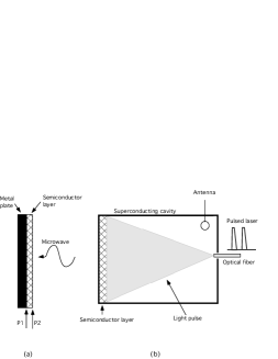
In our experimental scheme we shall simulate a mirror motion by changing the actively reflecting surface of a composite mirror. The mirror consists of a metal plate with a semiconductor wafer fixed on one side (see FIG. 1(a)). The semiconductor reflectivity is driven by irradiation from laser light, with photon energy corresponding to the semiconductor energy gap, so that it can switch from completely transparent to completely reflective for microwaves. By sending a train of laser pulses at a given frequency we get a mirror oscillating from position P1 to position P2. An advantage of this method is that the distance between P1 and P2 can be made of the order of a millimeter, compared to about 1 nm obtainable by mechanical oscillations. This leads to a layout as represented in FIG. 1(b). The composite mirror becomes a wall of a superconducting cavity. The laser pulses are guided into the cavity via an optical fiber. A small pickup antenna is also introduced in the cavity and the signal fed to high sensitivity electronics.
However a number of points need to be checked in order that we may state that this method is effective :
-
(1)
Is the mirror created in P2 as good as the one in P1 ?
-
(2)
Is it actually feasible to make the mirror appear and disappear in P2 at gigahertz frequencies ?
-
(3)
Is the of the cavity influenced by the presence of the semiconductor ?
-
(4)
Is the sensitivity of the pickup electronics good enough to detect the predicted number of created photons ?
Question (1) was tackled by inserting a semiconductor layer in a waveguide and measuring the reflected and the transmitted power under laser irradiation. It was proven that the semiconductor can reflect microwaves as effectively as copper. This test yields also another important parameter, that is the laser power needed to make a good mirror. This question arises from the fact that one needs to build a plasma of thickness equal to at least three skin depths (for the given microwave frequency) in order that it may be fully reflective. The energy needed is 1 J/cm2 per pulse in the microwave range BBCLPRZ .
The answer to question (2) can be found in literature MSABL . The mirror appearance at P1 is fast enough for gigahertz frequencies, since the transition time of the electrons is some femtoseconds, so that the dominant factor is the rise time of the laser pulse, which is in the hands of the experimenter. However the disappearance of the mirror depends on the recombination time of the electrons, which is a property of the semiconductor only. If one uses semi-intrinsic semiconductors one can obtain recombination times as low as 5–10 ps MSABL .
The answer to question (3) was straightforward. We measured the value of a niobium cavity brought to 4.6 K, determining the decay time of the loaded cavity, and got . Once the semiconductor wafer was inserted in the cavity no difference in the decay time (hence in ) was detected.
In order to answer question (4) a complete electronic chain was connected to the pickup antenna inserted in the cryogenic cavity. The first amplification stage was placed near the cavity at liquid helium temperature bradley . The cavity was then loaded with microwave pulses of decreasing power in order that the minimum detectable signal might be reached. The minimum signal detected had an energy of 0.1 eV, corresponding to about microwave (2.5 GHz) photons. By taking 100 measurements one arrives at photons. We think that further improvements in the electronic chain will allow us to detect even feebler signals. A by-product of this measurement regards the possible source of noise due to thermal radiation from the electron-hole plasma created in the semiconductor when the laser shines. We tried to measure this noise but it was below our sensitivity (in our frequency band).
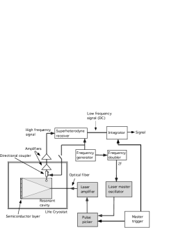
On the basis of our previous results a general layout for the detection of Casimir radiation is shown in FIG. 2. A niobium cavity at cryogenic temperature is placed in a vacuum vessel. A cryogenic amplifier bradley is connected by a transmission line to an inductive pickup loop coupled with the cavity in critical matching. A directional coupler is inserted between the cavity and the cryogenic amplifier to enable measurements of the resonance cavity reflection coefficient and calibration of the electronic chain. The signal output by the cryogenic amplifier is further amplified at room temperature, then processed by a superheterodyne receiver and eventually integrated over time. The laser light carried by the optical fiber is tuned in the near infrared and modulated in amplitude at a frequency exactly double the cavity resonance frequency. The generator drives a frequency doubler whose output turns to a low power laser master oscillator. The master oscillator yields a continuous signal from which a pulse picker selects the number of pulses required in each excitation stage. The total energy stored in the laser is limited, so must be the number of available pulses. Our present estimate is between and pulses for each run.
This experimental setup leaves open the possibility of changing many configuration parameters to help distinguishing real from spurious signals. We can change the master laser frequency and thus the oscillation mirror frequency to slightly detune the parametric resonance condition. Also we can vary the cavity temperature to study possible contributions from thermal radiation. Mirrors made with different semiconductor samples and with different thickness can be tried.
In order to show that our scheme leads to observable results we need to insert real numbers in the theoretical formulae and compare the predicted number of photons with our sensitivity. Several physical parameters are essentially already chosen, since a niobium cavity and an electronic chain have been used satisfactorily in the tests carried on to answer questions (3) and (4). The niobium cavity has transverse dimensions of 71 mm and 22 mm, and length mm. The cavity mode chosen was TE101 with eigenfrequency around 2.5 GHz. The semiconductor was GaAs with thickness mm. The excitation time duration for a single run, at 5 GHz, according to the number of pulses, can be between 0.2 and 2 s. Typically a run can be repeated after a few seconds. The following data can be used to estimate the number of photons produced by dynamic Casimir effect :
With formula (2), which is the more pessimistic, we find that this number is , well above our sensitivity.
The above figures foster our hopes that eventually some light will be shed on pressing open problems. In fact a good knowledge of quantum vacuum is of great importance in cosmology, both to the recurrent question of Einstein’s cosmological constant Wei , with its significance to the dark matter problem; and to the critical question of the birth of density inhomogeneities, ancestors of galaxies, from inflated quantum vacuum fluctuations Dav . Moreover a sound grasp of quantum vacuum dynamics is crucial in understanding some issues on the nature of quantum particles and on the relationships among vacuum noise, the concepts of information and entropy, and gravitation Dav .
We wish to thank L. Badan for technical help with cryogenics, E. Berto for mechanical support, and D. Corti for help with radio frequency measurements.
References
- (1) H.B.G. Casimir, Proc. K. Ned. Akad. Wet. 51, 793 (1948); H.B.G. Casimir and D. Polder, Phys. Rev. 73, 360 (1948).
- (2) M. Bordag, U. Mohideen and V.M. Mostepanenko, Phys. Rep. 353, 1 (2001).
- (3) G.T. Moore, J. Math. Phys. 9, 2679 (1976).
- (4) S.A. Fulling and P.C.W. Davies, Proc. R. Soc. London A 348, 393 (1976).
- (5) M. Kardar and R. Golestanian, Rev. Mod. Phys. 71, 1233 (1999).
- (6) S.K. Lamoreaux, Phys. Rev. Lett. 78, 5 (1997); U. Mohideen and A. Roy, Phys. Rev. Lett. 81, 4549 (1998); B.W. Harris, F. Chen and U. Mohideen, Phys. Rev. A 62, 052109 (2000); H.B: Chan et al., Science, 291, 1941 (2001); G. Bressi et al., Phys. Rev. Lett. 88, 041804 (2002).
- (7) A. Lambrecht, M.T. Jaekel and S. Reynaud, Phys. Rev. Lett. 77, 615 (1996).
- (8) V.V. Dodonov, in Modern Nonlinear Optics, edited by M.W. Evans, Adv. Chem. Phys. Ser. Vol. 119, p. 309 (Wiley, New York, 2001).
- (9) M. Crocce, D.A.R. Dalvit and F.D. Mazzitelli, Phys. Rev. A 64, 013808 (2001).
- (10) G. Schaller et al., Phys. Rev. A 66, 023812 (2002).
- (11) M.T. Jaekel, A. Lambrecht and S. Reynaud, in Proceedings of the Ninth Marcel Grossmann Meeting, edited by V.G. Gurzadyan, R.T. Jantzen and R. Ruffini, p. 1447 (World Scientific, 2002).
- (12) V.V. Dodonov, Phys. Lett. A 317, 378 (2003).
- (13) M. Crocce et al., Phys. Rev. A 70, 033811 (2004).
- (14) M. Uhlmann et al., Phys. Rev. Lett. 93, 193601 (2004).
- (15) H.E. Bömmel and K. Dransfeld, Phys. Rev. 117, 1245 (1960).
- (16) Z. Yu and S. Boseck, Rev. Mod. Phys. 67, 863 (1995).
- (17) V.B. Braginsky, C.M. Caves and K.S. Thorne, Phys. Rev. D 15, 2047 (1977).
- (18) E. Yablonovitch, Phys. Rev. Lett. 62, 1742 (1989).
- (19) Yu.E. Lozovik, V.G. Tsvetus and E.A. Vinograd, JETP Lett. 61, 723 (1995); Yu.E. Lozovik, V.G. Tsvetus and E.A. Vinograd, Phys. Scripta 52, 184 (1995).
- (20) C. Braggio et al., Rev. of Sci. Instr. 75, 4967 (2004).
- (21) C. Braggio et al., in preparation.
- (22) J. Mangeney et al., Appl. Phys. Lett. 80, 4711 (2002).
- (23) R.F. Bradley, Nucl. Phys. B (Proc. Suppl.), 72 137 (1999).
- (24) S. Weinberg, Rev. Mod. Phys. 61, 1 (1989); L. Bergström, Rep. Prog. Phys. 63, 793 (2000); M. Fukugita, Nature 422, 489 (2003).
- (25) P.C.W. Davies, Chaos 11, 539 (2001).