Improving the sensitivity of FM spectroscopy using nano-mechanical cantilevers
Abstract
It is suggested that nano-mechanical cantilevers can be employed as high- filters to circumvent laser noise limitations on the sensitivity of frequency modulation spectroscopy. In this approach a cantilever is actuated by the radiation pressure of the amplitude modulated light that emerges from an absorber. Numerical estimates indicate that laser intensity noise will not prevent a cantilever from operating in the thermal noise limit, where the high ’s of cantilevers are most advantageous.
Frequency modulation spectroscopy (FMS) [1, 2] has proven to be one of the most sensitive absorption-based spectroscopic techniques. The essential idea is that when a frequency modulated laser beam enters an absorption cell the emerging, partially absorbed beam is amplitude modulated (AM). If the modulation index of the frequency modulation is sufficiently small, the spectrum of the incident FM beam consists primarily of the peak at the carrier frequency and sidebands at , where is the modulation frequency. In addition to the component at the carrier frequency, the intensity of the output beam has a component that oscillates sinusoidally at with an amplitude proportional to the modulation index and to the difference in the attenuation coefficients of the absorber at the frequencies and . The output of a photodetector is electronically filtered and amplified, and the signal of interest that oscillates at is extracted by a mixer. An absorption spectrum is obtained by scanning the laser frequency over the spectral feature of interest.
It is important for FMS that there be little spectral overlap between the carrier and the sidebands. If the modulation frequency is not high enough, the spectral wings of the sidebands and the carrier will overlap, making the exact amplitude and phase balance required for full FM beat cancellation impossible. Thus, one of the major limiting factors in FMS is laser noise, which requires that the modulation frequency be large compared with the laser bandwidth. For laser bandwidths of 10-100 MHz, for instance, modulation frequencies in the 100-1000 MHz range are desirable. However, electronic detection systems, consisting of a photodetector and several amplification cascades, produce an additional noise which increases with increasing frequency, so that the shift to higher modulation frequency could be inefficient. The highest sensitivity of FMS is usually achieved with well stabilized, low-power semiconductor lasers. While it is possible to substantially reduce the laser technical noise and bandwidth in these lasers, this is generally incompatible with the relatively high laser powers required, for instance, for remote sensing or long-length multipass cells.
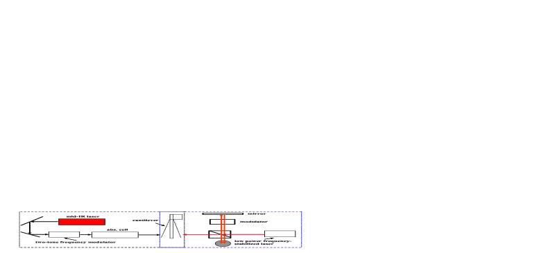
In this letter we suggest the use of nano-mechanical cantilevers (nano-resonators) as filters with much higher factors than are currently possible by conventional methods. In this approach the AM signal that emerges from the absorption cell (or is backscattered in the case of remote sensing) actuates a cantilever by resonant light pressure or by optical gradient forces. The cantilever functions both as a high-frequency detector and as a high- filter. As discussed below, the use of cantilevers in FMS in this way could offer the possibility of detecting molecules with unprecedented sensitivity.
The lower limit on , where is the absorption coefficient and is the total propagation length, can be estimated from the condition that the signal-to-noise ratio () be unity. can be written as
| (1) |
where is the vibrational amplitude of the cantilever, is the root mean square (rms) vibration noise induced by the laser shot noise, is the rms vibrational thermal noise, and is the vibrational noise induced by the laser intensity noise. Substitution in (1) of the expressions for the vibrational amplitudes gives
| (2) |
where is the reflection coefficient, is the spring constant, is Boltzmann’s constant, is the temperature, is the incident laser power, is the fundamental frequency of the cantilever, and is the laser intensity noise, where is the relative intensity noise (RIN). Consider as an example the following parameter values: K, N/m, , , W, and MHz. In this case the laser noise dominates if the RIN satisfies the inequality . This value of the RIN is typical for solid state lasers [3]. Neglecting the shot noise and thermal noise, we obtain . The condition then gives .
Let us compare this estimate of the minimal with the sensitivity of conventional electronic detection. The photodetection usually involves at least three electronic stages [4]. The first stage is the photodetector and preamplifier or the photomultiplier, or avalanche photodiode; the second stage is the lock-in-amplifier; and the third stage is the output amplifier. Each stage produces noise. The noise of the two first stages increases significantly at higher modulation frequencies. We can characterize the noise by the noise figure (where and are the in the input and output signals, correspondingly). For a modulation frequency greater than 10 MHz the noise figure for the photodetector plus preamplifier is about dB; for the lock-in-amplifier dB - 5 dB; and for the output amplifier dB. Thus the total noise figure is dB. The for electronic photodetection can be written as
| (3) |
where . The symbols in this equation are electric charge , detector quantum efficiency , photon energy , bandwidth , resistance , and . The first term in the denominator corresponds to the laser shot noise, the second term to thermal noise, and the third term to the laser intensity noise. For the parameter values , , , and dB, the laser intensity noise dominates, and the condition for the minimum detectable absorption gives .
To avoid additional loss of signal, the effective bandwidth should exceed the bandwidth of modulation. For the modulation frequency GHz and the (highest) quality factor , the bandwidth Hz. The assumption that the cantilever bandwidth implies , i.e., the smallest measurable absorption using the cantilever is less than the corresponding value for electronic detection by at least an order of magnitude.
By choosing the cantilever resonance frequency appropriately, the proposed sensor can be made to operate in the thermal noise limit. To see this, let us assume a laser noise spectrum , where is the spectral density of relative intensity noise (RIN) at the center of the spectral distribution around the peak of laser intensity noise at the frequency . If the cantilever is to operate in the thermal noise limit the following condition must be satisfied: , or
| (4) |
where . For MHz, MHz, and for the other parameters assumed above, the inequality (4) gives , or MHz.
We have assumed that radiation pressure rather than the photothermal effect produces the dominant force in exciting the cantilever vibrations. Experimental evidence suggests that this is indeed the case for Si cantilevers [5, 6]; namely, the fact that the cantilever could be actuated at very high temperatures, where thermal gradients are much smaller than the surface temperature, suggests that photothermal effects are relatively small compared with radiation pressure.
Large resonance frequencies , and therefore small cantilevers, are generally desirable for increasing the sensitivity. If the cantilever is smaller than the spot size of the beam incident upon it, actuation of the cantilever vibrations may be inefficient. In this case one could use a scheme of apertureless near-field microscopy. The tip is put in close proximity to the cantilever surface, and focused light illiminates the tip-surface region. The light intensity near the tip apex exceeds the external intensity by an enhancement factor that could be in the case of a plasmon resonance with a metallic tip. Near the tip the field is very inhomogeneous, implying that the gradient force could exceed the force of light pressure, depending on the geometry.
Optical actuation of cantilevers by light pressure has been demonstrated [5, 6]. In the experiments of Yang et al., deflections of a m2 cantilever with 680-nm, 40-W laser radiation of beam size m2 were observed. Deflections were observed for temperatures as high as 780 C. Their cantilever had a factor and a spring constant N/m. For these parameters we estimate a force sensitivity N, in rough agreement with the value quoted by Yang et al. The condition (4) for the cantilever to operate in the thermal noise limit is found to be easily realized for these parameters. Such numerical estimates support the viability of the proposed cantilever sensor. Note also that in Reference [7] a cantilever quality factor up to was achieved for driven oscillations of the cantilever for a laser power of a few hundred microwatts.
In conclusion, we have presented estimates indicating that nano-mechanical cantilevers can be employed as high- filters to circumvent laser noise limitations on the sensitivity of frequency modulation spectroscopy.
Acknowledgments
We thank Professor Umar Mohideen and Dr. C. E. Strauss for helpful discussions. This work was supported by the Department of Energy under the contract W-7405-ENG-36 and DOE Office of Basic Energy Sciences, and by the Defense Advanced Research Projects Agency.
REFERENCES
- [1] G.C. Bjorklund, Opt. Lett. 5, 15 (1980).
- [2] Reviews of the subject are given, for instance, by P. Werle, Infra. Phys. Tech. 37, 59 (1996); P. Kluczynski et al., Spectrochim. Acta A 51, 2211 (2001); and K. Song and E.C. Jung, Appl. Spectrosc. Rev. 38, 395 (2003).
- [3] S. Taccheo et al., IEEE Phot. Tech. Lett. 13, 19 (2001).
- [4] J. Silver, Appl. Opt. 31, 707 (1992).
- [5] O. Marti et al., Ultramicrosc. 42-44, 345 (1992).
- [6] J. Yang, T. Ono, and M. Esashi, Appl. Phys. Lett. 77, 3860 (2000).
- [7] M. Zalalutdinov et al., Appl. Phys. Lett., 79, 695 (2001).