Cavity QED with optically transported atoms
Abstract
Ultracold 87Rb atoms are delivered into a high-finesse optical micro-cavity using a translating optical lattice trap and detected via the cavity field. The atoms are loaded into an optical lattice from a magneto-optic trap (MOT) and transported 1.5 cm into the cavity. Our cavity satisfies the strong-coupling requirements for a single intracavity atom, thus permitting real-time observation of single atoms transported into the cavity. This transport scheme enables us to vary the number of intracavity atoms from 1 to 100 corresponding to a maximum atomic cooperativity parameter of 5400, the highest value ever achieved in an atom–cavity system. When many atoms are loaded into the cavity, optical bistability is directly measured in real-time cavity transmission.
pacs:
Many applications in quantum information science require the coherent and reversible interaction of single photon fields with material qubits such as trapped atoms. Quantum states can be transferred between light and matter—respectively offering long range communication and long-term storage of quantum information. This important paradigm is the heart of cavity QED systems, which are largely focused on creating laboratory systems capable of reversible matter-photon dynamics at the single photon level BermanBook . To achieve this, a small high-finesse build-up cavity is used to tremendously enhance the electric field per photon and hence the interaction strength of a single photon with the cavity medium (e.g. atoms). For a single atom in the cavity, the interaction strength is given by the single photon Rabi frequency, , and coherent dynamics is achieved for , where is the the cavity field decay rate and is the atomic spontaneous emission rate.
There have been spectacular recent successes in cavity QED research brought about by the merging of optical cavity systems with ultracold neutral atoms cqedreviewopt , including real-time observation Mabuchioptlet ; Hood1 ; Rempe1 and trapping Ye ; Hood2 ; Rempe2 ; McKeever of single atoms in optical cavities, real-time feedback control on a single atom Rempe3 , and single photon generation Rempe4 ; Rempe5 . Together with the remarkable experimental work in microwave cavity QED cqedreviewmic and the future prospects for cavity QED with trapped ions Waltherioncavity ; Blattioncavity , the field is well-poised to contribute significantly to the development of quantum information science. Indeed, current cavity QED parameters are sufficient for existing quantum gate protocols with fidelities percent PGCZ ; Walther ; You1 ; You2 , and the systems are principally limited by the lack of a scalable atomic trapping system to provide adequate control over atom motional degrees of freedom.
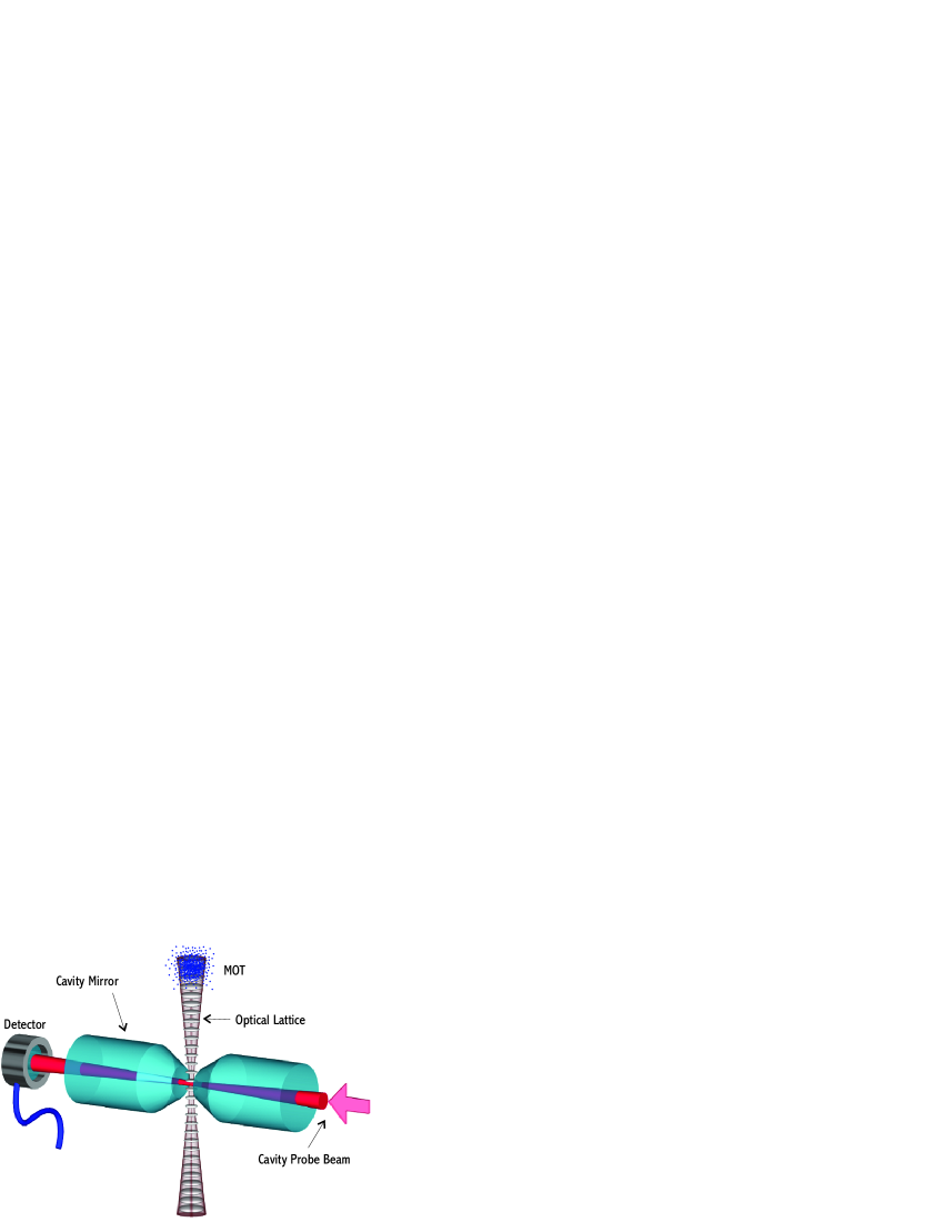
Our strategy for overcoming this limitation is to employ optical dipole trapping fields independent from the cavity and orthogonal to its axis as illustrated in Fig. 1 apstalk . Atoms are trapped in the anti-nodes of the standing wave formed by two focused counter-propagating laser beams. Translating the standing wave controllably introduces atoms in this 1-D chain in and out of the cavity mode. This trapping geometry will ultimately allow entanglement of 100 distiguishable atoms in two such parallel chains or in a single chain using nearest-neighbor interactions.
In this Letter, we describe an experimental realization of a cavity QED system with optically trapped and transported atoms. Single and multiple atoms are transported into the cavity and detected—in the latter case, we observe optical bistability in the cavity output due to the cooperative interaction of the atoms with the cavity field. By adjusting the initial loading conditions of the optical traps, the number of intracavity atoms, , can be varied from 1-106 atoms. Our unique combination of strong coupling parameters and large maximum intracavity atomic density ( cm-3), provide for a measured atomic cooperativity, =, up to 5400, the highest value ever achieved in an atom-cavity system. The cooperativity parameter is an important figure of merit both for single atom () protocols and for many-atom, ensemble based protocols including light storage and single photon generation Zoller ; SoMo ; Kuga ; Lukin ; kuzmich .
The experiment begins 1.5 cm above the optical cavity with a laser-cooled sample of 87Rb atoms collected in a beam-loaded MOT as previously described in storagering . The cavity itself consists of two 1 mm diameter super-polished mirrors with 10 cm radii of curvature separated by 75 m. The measured finesse of the cavity is . The relevant cavity QED parameters for our system are MHz, placing our system well into the strongly coupled regime and yielding a single atom cooperativity parameter, =.
Maintaining the cavity on resonance requires cavity length stability better than fm ( nm is the resonant wavelength of the cavity ) and represents a significant challenge. To achieve the required stability while providing the necessary length adjustability, both mirrors are mounted directly on a flat rectangular piezoelectric transducer (PZT) which in turn is attached to a copper block. The block is suspended inside a vacuum chamber by 4 Cu-Be springs to provide an in-vacu isolation system with a 3.5 Hz resonance. Both the copper block and the PZT have holes drilled vertically to accommodate the optical lattice beams. The length of the cavity is controlled by applying a voltage to the PZT. The isolation system together with low-noise electronics provides excellent passive stability (10 fm/s drift) of the cavity length.
Optical dipole traps connecting the MOT with the cavity are used to transport the atoms to the cavity. We employ both travelling wave and standing wave beam configurations to confine the atoms. In the former case, the atoms are confined transversely and are guided under the influence of gravity into the cavity. For the standing-wave configuration, two counter-propagating beams are used to form a 1-D lattice, and the atoms are confined vertically at the anti-nodes of the trap beams. The vertical motion of the atoms can then be controlled by varying the difference frequency of the beams using two phase-locked acousto-optic modulators, which creates a ‘walking-wave’ with velocity , where is the trapping wavelength conveyor . The optical traps are loaded directly from the MOT, following sub-doppler cooling of the atoms to 4 K.
In our first experiment, the trapping laser beam is generated from a diode laser operating at 782.5 nm (2.25 nm above of the rubidium D2 line). A single travelling wave of 16 mW of laser power is focused to a intensity waist of = 30 m at the cavity. This yields a transverse trap depth of 72 K at the cavity. At the location of the MOT, the transverse trap depth is only 4 K due to the divergence of the beam to a waist of 130 m. We load up to 10 87Rb atoms into our MOT, and typically 10 are transferred into the optical guide. After the MOT light is extinguished, the atoms fall under gravity towards the cavity while being compressed transversely in the guide.
The atoms delivered to the cavity are detected as modifications in the transmission of a weak cavity probe beam, tuned to the 5S1/2F 5P3/2F’=3 transition in 87Rb. For our cavity, the critical photon number (the average number of photons producing an intracavity intensity of Isat) is , and single atoms are readily detected with probe strengths up to 1.9 pW corresponding to intracavity fields of . The probe beam is detected with balanced-heterodyne detection with typical bandwidth of 30 kHz. The cavity length is adjusted such that the cavity’s resonant frequency is typically detuned rad/s below both the atom’s () and the probe beam’s () frequency.
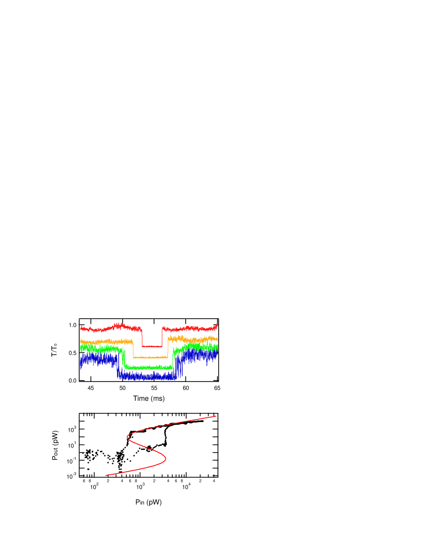
The cavity transmission is shown in Fig. 2 as the atom cloud falls through the cavity for several different input powers. Although the atomic density time-profile through the cavity is approximately gaussian with a width ( 1.5 ms FWHM) determined by the cloud temperature, the cavity transmission switches very abruptly and at different times for different powers. For the weakest probe powers, the individual atom transits are observed as spikes in the transmission at the leading and trailing edges of the cloud.
The abrupt non-linearity in the cavity transmission is due to the absorptive optical bistability of the system resulting from the collective interaction of many radiating atoms with the cavity field. For many atoms, the transmission of the probe beam is given by the steady state optical bistability equation where and are the output and input intensities, , normalized to the saturation intensity and cavity transmission and Orozco . For , this equation predicts two stable output powers for a given input power as shown in the theoretical trace of Fig. 2b as well as hysteresis in the switching power due to the unstable branch with negative slope.
To measure the bistability directly, we allow the atomic cloud to fall into the cavity with the probe beam off, then we quickly ramp the probe up to a high value and then down to zero again while the atoms are in the cavity. The results are shown in Fig. 2b., where the hysteresis is clearly evident in the 10-fold difference in the switching power. This data is taken from a single experimental run in real time. The data agrees very well with the theoretical curve for high input powers. The agreement at lower power is less satisfactory although the noise floor of the heterodyne detection complicates the analysis of these data.
Coming back to the traces in Fig. 2a, the different switching times can be understood as follows: as the atomic cloud falls through the cavity, the intracavity atomic density (and hence the cooperativity ) first increases then decreases. For constant input power, the growing cooperativity shifts the bistability curve to the right until the transmission falls to the lower branch. Then, as the cloud continues through the cavity, falls and the transmission then jumps back to the higher branch. For higher input powers, the switching points occur at higher intracavity densities and the time window for the drop in transmission becomes more narrow.
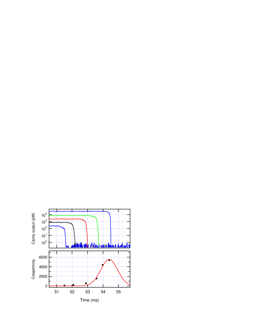
Indeed, the intracavity density at the instant when the cavity output power drops can be determined by implicitly solving the bistability equation for with a known input. By increasing the probe power, we can map out the cooperativity and the atom number vs time. Fig. 3 shows data collected in this manner. Cooperativities of up to 5400 were measured corresponding to an maximum intracavity atom number of 100 and an atomic density 1010 cm-3 inside the cavity. For these data, a Ti:Sapphire laser at 850 nm with 400 mW of power focused to 22 m was used to increase the trap depth to 238 K, which increased the number of atoms loaded into the cavity. In addition, a repumping beam was added perpendicular to the cavity axis to prevent atoms that are pumped into the ground state by the cavity probe beam from becoming dark to the probe light McKeever . The maximum switched probe output power is 8 nW, corresponding to an intracavity intensity of . It is remarkable that such a large intensity can be extinguished by only 100 atoms.
In our final experiment, we use the Ti:Sapphire laser to generate two counter-propagating 200 mW beams for the optical lattice. The beams provide a maximum trap depth of 476 K at the cavity, while at the location of the MOT, the trap depth is only 7 K due to the divergence of the beam waist to 185 m. After the atoms are loaded into the lattice, we accelerate the occupied lattice sites down into the cavity mode. The trapped atoms pass through the cavity and are brought momentarily to rest. Then they pass through the cavity again as the lattice velocity is reversed and they are returned to their original position. The maximum velocity of the atoms 30 cm/s, and the maximum acceleration imparted is 1.5. The middle graph in Fig. 4 shows the position and velocity of the lattice sites measured relative to the cavity axis.
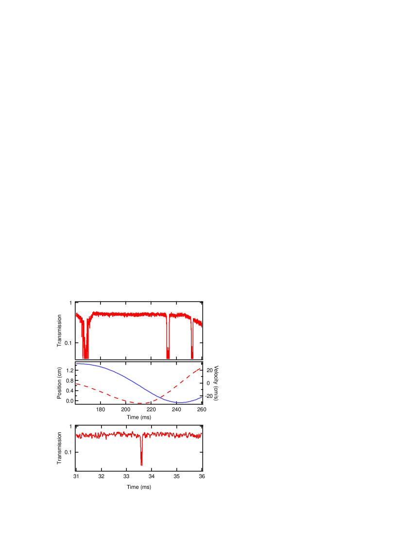
In Fig. 4, the measured transmission through the cavity is shown for the lattice-transported atoms. The transmission drops at 120 ms and 140 ms show the atoms on their way down through the cavity and back up again. The first feature at 55 ms is due to atoms that are unbound at lattice sites, but still channelled through the cavity. The gradual drop in the baseline transmission for is due to the cavity drifting out of resonance due to heating of the cavity mirrors caused by absorption of the lattice beams.
With a critical atom number (number of atoms coupled to the cavity required to alter the atom-cavity response significantly) of , our cavity is sensitive to single atoms within the mode. We can load very few atoms into our MOT by using low light levels and short loading times. When a single atom is delivered into the cavity mode, the dressed state of the combined atom-cavity system splits the single resonant frequency into two peaks, separated by the single photon Rabi frequency, , which results in a drop in cavity transmission jc . Fig. 4a shows a single atom transported through the cavity mode. This atom has been accelerated at m/s2 and is delivered to the cavity 21 ms before gravity delivers the unbound atoms.
Currently, our ability to manipulate the atoms in the lattice is limited by the lifetime of our lattice trap. While the lifetime of a single travelling wave trap is s, in the lattice configuration, the lifetime falls to 104 ms. We suspect that power fluctuations in our Ti:Sapphire FORT beams lead to parametric heating in the lattice configuration Thomas . Indeed, a new solid state pump laser for the Ti:Sapphire has shown significant lifetime improvements in an independent experiment.
In conclusion, we have realized a cavity QED system with optically trapped and transported atoms. Groups of atoms can be deterministically delivered to the cavity mode. The successful demonstration of this scalable trapping geometry opens exciting opportunities in the implementation of quantum gate protocols. Additionally, the strong coupling parameters of our cavity and the large maximum intracavity atomic density, provide for a measured atomic cooperativity, , up to 5400, the largest observed to-date for atom-cavity systems.
We would like to acknowledge helpful discussions with A. Kuzmich and L. You. This work was supported by ARDA/NSA/DARPA/ARO (ARO DAAD19-01-1-0667) and the NSF (PHY-0113831).
References
- (1) H.J. Kimble in “Cavity Quantum Electrodynamics,” (Edited by P. Berman), (Academic Press, San Diego, 1994).
- (2) for recent reviews see H. Mabuchi and A.C. Doherty, Science, 298, 1372 (2002) and H.J. Kimble, Phys. Scr. T76, 127 (1998).
- (3) H. Mabuchi et al. Opt. Lett. 21, 1393 (1996).
- (4) C.J. Hood et al., Phys. Rev. Lett. 80, 4157 (1998).
- (5) P. Muenstermann et al. Phys. Rev. Lett. 82, 3791 (1999).
- (6) J. Ye, D. W. Vernooy, and H. J. Kimble, Phys. Rev. Lett. 83, 4987 (1999).
- (7) C. J. Hood, et al., Science 287, 1447 (2000).
- (8) P. W. H. Pinkse, T. Fischer, P. Maunz, and G. Rempe, Nature 404, 365 (2000).
- (9) J. McKeever, et al., Phys. Rev. Lett. 90, 133602 (2003).
- (10) T. Fischer, et al., Phys. Rev. Lett. 88, 163002 (2002).
- (11) A. Kuhn et al, Phys. Rev. Lett. 89, 067901 (2002).
- (12) M. Hennrich et al, quant-ph/0208188 v1 (29 Aug 2002).
- (13) for recent reviews see J. M. Raimond, M. Brune, S. Haroche, Rev. Mod. Phys. 73, 565 (2001) and H. Walther, Adv. Chem. Phys. 122, 167 (2002).
- (14) G.R. Guthöhrlein, et al., Nature, 414, 49 (2001).
- (15) A.B. Mundt, et al., Phys. Rev. Lett. 89, 103001 (2002).
- (16) T. Pellizzari et al, Phys. Rev. Lett. 75, 3788 (1995).
- (17) J. Pachos and H. Walther, Phys. Rev. Lett. 89, 187903 (2002).
- (18) X. X. Yi et al, Phys. Rev. Lett. 90, 097902 (2003).
- (19) L. You et al, Phys. Rev. A 67, 032308 (2003).
- (20) L.-M. Duan et al, Nature 414, 413 (2001)
- (21) A. S. Srensen and K. Mlmer, Phys. Rev. A 66, 022314 (2002)
- (22) Y. Shimizu et al, Phys. Rev. Lett. 89, 233001 (2002).
- (23) M. D. Lukin, Rev. Mod. Phys. 75, 457 (2003)
- (24) A. Kuzmich et al, Nature 423, 731 (2003)
- (25) J.A. Sauer, M.D. Barrett, and M.S. Chapman, Phys. Rev. Lett., 87, 270401 (2001).
- (26) S. Kuhr, et al., Science, 293, 278 (2001).
- (27) A. T. Rosenberger, L. A. Orozco, H. J. Kimble, and P.D. Drummond, Phys. Rev. A 43, 6284 (1991).
- (28) M. Barrett, A. Prasad, and M. S. Chapman, 1999 Centennial meeting of the APS SB13-7, (1999).
- (29) E. T. Jaynes and F. W. Cummings, Proc. IEEE 51 89 (1963).
- (30) T. A. Savard et al, Phys. Rev. A 56, R1095 (1997).