Present Address: ]Dept. of Physics, Technion, Haifa ISRAEL Present Address: ]NIST Optoelectronics Division
Experimental demonstration of a controlled-NOT wave-packet gate
Abstract
We report the experimental demonstration of a controlled-NOT (CNOT) quantum logic gate between motional and internal state qubits of a single ion where, as opposed to previously demonstrated gates, the conditional dynamics depends on the extent of the ion’s wave-packet. Advantages of this CNOT gate over one demonstrated previously are its immunity from Stark shifts due to off-resonant couplings and the fact that an auxiliary internal level is not required. We characterize the gate logic through measurements of the post-gate ion state populations for both logic basis and superposition input states, and we demonstrate the gate coherence via an interferometric measurement.
pacs:
03.67.Lx, 32.80.QkConsiderable attention is now focused on developing quantum computer technology across a diverse set of physical systems QC1 ; QC2 . Using laser cooled trapped atomic ions for quantum computing and information processing carries many advantages as most of the basic building blocks of quantum computing have been demonstrated, including high efficiency state initialization and read-out Monroe95a ; Meekhof96 ; King99 ; Ben-Kish02 , entangling gates Monroe95b ; Sackett00 , individual addressing Nagerl99 , and long qubit coherence times Wineland98 ; Roos99 . Areas of concentration for current work with trapped ions include simplifying quantum logic operations and increasing their fidelity, as well as scaling up the complexity of computations Sackett01 ; Rowe02 ; Kielpinski02 . Here we report the experimental demonstration of a CNOT logic gate between motional and internal-state qubits of a trapped 9Be+ ion that requires fewer resources than that of Ref. Monroe95b . This gate is fundamentally different than previously demonstrated gates in that the conditional dynamics depend on the size of the atomic wave-packet compared to the wavelength of the applied radiation Monroegate .
The quantum CNOT logic gate between two qubits has become a paradigm for quantum computing because universal quantum computation can be carried out with the CNOT gate and single qubit rotations QC1 . A CNOT gate toggles the state of a target qubit depending on the state of a control qubit. If the logic basis states are labelled as and , then the general target state should be unaffected if the control qubit is in the state and transformed to for a control qubit. Here and are taken to be arbitrary angles to designate the most general superposition state. Based on a previous proposal Monroegate , we demonstrate a CNOT gate in the trapped ion system that requires only a single laser pulse and no auxiliary levels, and is therefore simplified compared to a previous implementation that required three laser pulses and an auxiliary internal state Monroe95b . Furthermore, the method employed here is free from level shifts introduced by the gate coupling.
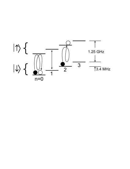
The qubits in our implementation of the CNOT gate are spanned by the internal and motional levels of a single trapped 9Be+ ion Monroe95b ; Sackett01 . The target states, abbreviated by the analogous spin- states and , are the and hyperfine states of the 9Be+ electronic ground state. The control qubit consists of the ground and second excited states ( and ) of the quantized states of the harmonic ion motion along the trap axis or direction. Coherent manipulation of the four qubit states and the CNOT gate action is accomplished by driving two-photon Raman transitions using two laser beams detuned from the transitions Monroe95b ; Sackett01 . The laser beams can be used to change just the spin state of the ion by driving the “carrier” transition with a laser beam frequency difference GHz. By tuning the frequency difference to (where is the harmonic oscillator frequency) both the spin state and motional level can be changed via driving the order sideband: . We refer to the “blue” sidebands for and “red” sidebands for . In this way, any of the four qubit eigenstates (, , , ) and any superposition of them can be generated from the initial state that is prepared by optical pumping and laser cooling Meekhof96 .
The CNOT gate is implemented by applying a single Raman laser pulse on the carrier transition. The gate action relies on tuning the laser-atom interaction by adjusting the relative overlap of the motional qubit states with the laser field. The carrier Rabi rate for the motional state is reduced compared to the state because the state has a broader spatial extent and the ion averages over the laser wave Wineland98 ; debyenote . This effect is a manifestation of the wave-packet nature of the ions – we cannot obtain the observed interaction with the laser by assuming that the ions are point particles suppression .
By adjusting the trap strength and therefore manipulating the Lamb-Dicke parameter , the ratio of the carrier transition Rabi rates for the and states is set to 4/3 in the experiments reported here. Here is the two-photon Rabi rate for the coupling and depends on the trap frequency through where is the ion mass and is the wavevector difference of the Raman laser beams along the direction Wineland98 . To operate the gate, the carrier transition is driven for a time , evolving the state amplitudes according to and (cf. Eq. 23 of Wineland98 ). The amplitudes are defined so that the state of the ion is given by . The pulse time is chosen so that the state undergoes two full Rabi cycles, or a “-pulse” (). For the same pulse time the state experiences 1.5 Rabi cycles, or a “-pulse” (). Under these conditions, the target bit (spin) of the atom flips if the control bit (motional state) is in the state and stays the same for the state, accomplishing the CNOT gate logic (see Fig. 1). The phase acquired on the state can be removed by an appropriate phase shift in a subsequent operation. The scheme employed here is a specific case of more general possibilities outlined in Monroegate .
A single 9Be+ ion is trapped in a linear Paul trap using a combination of static and time varying electric fields to produce a 3-dimensional harmonic confining potential Rowe02 . The harmonic oscillator frequency along the trap () axis is set to 3.4 MHz by adjusting the static potentials in order to adjust so that . State preparation and qubit manipulation are accomplished using a pair of non-collinear Raman beams Meekhof96 ; Sackett01 . The beams are detuned by GHz from the electronic to transition at 313 nm, and the intensity in the beams is set to give kHz.
Each experiment begins by initializing the ion qubit into the state with 99.9% probability using resolved-sideband Raman cooling and optical pumping Monroe95a ; Leibfried97 ; King99 . The gate input state is then prepared using combinations of carrier and sideband transitions. After applying the gate, the experimental observable is the spin state of the ion which is determined through resonance fluorescence measurements Rowe01 ; Sackett01 . The ion is illuminated for 200 s by a polarized beam detuned by -10 MHz from the electronic , to () excited state transition. The histogram of scattered photons collected onto a photo-multiplier tube (PMT) is recorded for 200 experiments with identical parameters. The bright state is distinguished from the dark state by the difference in photon scattering rates. The probability to find the ion in the state is determined by fitting the measured fluorescence histogram to reference histograms measured from the and states. The fit uncertainty is typically less than 1%.
We characterize the logic gate by measuring both the logic truth table and the gate coherence. The CNOT gate truth table is determined by measuring the ion spin output state for different input eigenstates, in analogy with a classical logic gate. The measured output state for each of the logic basis states is shown in table 1. The four basis states are generated from the state using combinations of carrier and sideband -pulses Meekhof96 : the state is prepared from the by driving a -pulse on the carrier transition, the state is prepared by driving a -pulse on the first blue sideband () and then first red sideband (), and the state is prepared by driving a -pulse on the second blue sideband (). The input spin state of the ion is prepared with better than 96% accuracy. After input state preparation, the CNOT gate is applied by driving the carrier transition for , and then the ion spin state is measured. For each of the basis states, we achieve at least 95% accuracy in the CNOT logic off_resonant .
| n=0 | ||
|---|---|---|
| n=2 |
A key feature of quantum logic gates is the ability to “parallel process” superposition input states, a capability that classical logic lacks. Figure 2 shows the gate acting on the superposition input state . The input state is prepared by applying a -pulse on the second blue sideband starting from the state. The CNOT gate should flip the spin if the ion is in the state, so that the expected output state is and the ion is always found in the state. Figure 2 shows the measured probability to find the ion in the state as the carrier transition is driven for an increasing period of time. The beating observed is due to the two different carrier Rabi oscillation frequencies for the and state. A fit of the data in figure 2 to a sum of two sine functions gives . Our ability to set the desired ratio is limited in part by slow drift in caused by changing stray electric fields with spatial curvature. The accuracy of the gate logic is robust to deviations from , and, at the gate time, the ion is in the state 98% of the time.

Measuring the population in the state after applying the gate to a superposition input state does not determine that the CNOT gate acts coherently. To verify the gate coherence, we perform an interferometric phase measurement using the input state . This state is prepared from by applying a -pulse on the first blue sideband with a phase followed by a -pulse on the first red sideband. If the gate acts coherently on the input state, then the pure state is generated by the gate. Alternatively, if the gate transfers population incoherently then the state after the gate is characterized by the mixed state density matrix . To test for the coherence, after applying the CNOT gate to the input state a analysis pulse on the second blue sideband (with arbitrary but constant phase) is applied and then is measured. For coherent gate action, the final state after the analysis pulse should oscillate fully between the states and , while incoherent gate behavior produces no dependence on . Figure 3 shows the observed oscillations in as the phase is varied demonstrating the coherence of the gate. The lack of 100% contrast in the fringes is due to imperfections in the state and analysis pulses as well as limited gate fidelity.

A novel feature of the gate demonstrated here is the absence of level shifts introduced by the gate coupling. Other CNOT and phase gates for the trapped ion system are affected by shifts in the energy of the levels involved in the gate. These level shifts can be caused by the existence of off-resonant couplings to “spectator” levels, for example Wineland98 ; Steane00 . If the energy spacing between levels changes when the coupling is applied, a phase error can accumulate over the course of an extended computation which then must be corrected. In the limit where the two-photon Rabi rate is small compared to the trap frequency, the energy shift for and caused by the sideband couplings can be expressed as:
| (1) |
Here, the shift is caused by the presence of off-resonant sideband couplings to higher and lower energy motional states. Pairs of coupled levels ( and ) shift in energy by the same amount, so that the difference relevant to quantum logic operations vanishes. Physically this occurs because there are an equal number of equally detuned red and blue sideband transitions from states with the same error . Equation 1 is valid only when coupling to non-resonant spectator levels can be considered as a perturbation. As increases, the amplitudes of the spectator levels become significant so that after applying the gate information is lost to states outside the computational basis off_resonant . Therefore, as with the gate of Refs. Monroe95b and CZ , the gate speed () must be kept below the ion oscillation frequency.
In conclusion, using a single trapped 9Be+ ion we have demonstrated a CNOT quantum logic gate between a motional and a spin qubit that is simplified compared to previous implementations. To perform a CNOT gate between two ions, the state of the control ion must first be mapped onto the selected motional mode, followed by a CNOT operation between the motion and target ion as in the original proposal of Cirac and Zoller CZ . However, the gate shown in this work does not require auxiliary levels, uses only a single laser pulse, and is free from level shifts caused by the gate coupling. The ability to manipulate the motional states of the ion was enabled in part by improvements in ion trap technology; the latest generation of NIST ion traps exhibits a factor of 100 reduction in the motional state heating rate Rowe02 . With anticipated further reductions in the heating rate and improvements in system stability, the conditions for fault-tolerant computation with trapped ions appears feasible.
The authors thank Murray Barrett and David Lucas for suggestions and comments on the manuscript. This work was supported by the National Security Agency (NSA) and Advanced Research and Development Activity (ARDA) under contract No. MOD-717.00. This paper is a contribution of the National Institute of Standards and Technology and is not subject to U.S. copyright.
References
- (1) M.A. Nielsen and I.L. Chuang, Quantum Computation and Quantum Information, Cambridge, 2000.
- (2) D. Bouwmeester, A. Ekert, A. Zeilinger, The Physics of Quantum Computation, Springer-Verlag, 2001.
- (3) C. Monroe et al., Phys. Rev. Lett. 75, 4011 (1995).
- (4) D.M. Meekhof, C. Monroe, B.E. King, W.M. Itano, and D.J. Wineland, Phys. Rev. Lett. 76, 1796 (1996).
- (5) B.E. King et al., Phys. Rev. Lett. 83, 4713 (1999).
- (6) A. Ben-Kish et al., submitted for review.
- (7) C. Monroe et al., Phys. Rev. Lett. 75, 4714 (1995).
- (8) C.A. Sackett et al., Nature 404, 256 (2000).
- (9) H. C. Nägerl et al., Phys. Rev. A 60, 145 (1999).
- (10) D. Wineland et al., J. Res. Natl. Inst. Stand. Technol. 103, 259 (1998).
- (11) Ch. Roos et al., Phys. Rev. Lett. 83, 4713 (1999).
- (12) C.A. Sackett, Quant. Inf. Comp. 1, 57 (2001).
- (13) M.A. Rowe et al., Quant. Inf. Comp. 4, 257 (2002).
- (14) D. Kielpinski, C. Monroe, D.J. Wineland, Nature 417, 709 (2002).
- (15) C. Monroe et al., Phys. Rev. A 55, R2489 (1997).
- (16) D. J. Wineland and W. M. Itano, Phys. Rev. A 20, 1521 (1979).
- (17) A suppression of the Rabi rate due to radio-frequency micromotion was observed in Q.A. Turchette et al., Phys. Rev. Lett 81, 3631 (1998); however, this suppression was not state dependent and would apply to a point particle.
- (18) D. Leibfried et al., J. Mod. Optics 44, 2485 (1997).
- (19) M.A. Rowe et al., Nature 409 791 (2001).
- (20) We estimate for the experimental conditions described in this manuscript that less than 0.05% of the ion population is moved outside of the =0,2 levels by off-resonant excitation of sideband transitions. This effect can be minimized through an appropriate choice for the intensity envelope of the laser pulse.
- (21) A. Steane et al., Phys. Rev. A 62, 042305 (2000).
- (22) The level shifts introduced by the CNOT gate demonstrated in this work were analyzed in Steane00 , but the authors did not consider the balancing contributions that cause to vanish.
- (23) J. I. Cirac and P. Zoller, Phys. Rev. Lett. 74, 4091 (1995).