Further author information: (Send correspondence to
B.C.S.)
B.C.S.: E-mail: barry.sanders@mq.edu.au, Telephone: +61 2
9850 8935
Photon counting schemes and performance of non–deterministic nonlinear gates in linear optics
Abstract
The performance of nondeterministic nonlinear gates in linear optics relies on the photon counting scheme being employed and the efficiencies of the detectors in such schemes. We assess the performance of the nonlinear sign gate, which is a critical component of linear optical quantum computing, for two standard photon counting methods: the double detector array and the visible light photon counter. Our analysis shows that the double detector array is insufficient to provide the photon counting capability for effective nondeterministic nonlinear transformations, and we determine the gate fidelity for both photon counting methods as a function of detector efficiencies.
keywords:
Quantum computation, photodetector models, nonclassical light1 Introduction
Nonlinear transformations in quantum optics can yield dramatic nonclassical effects, particularly if the Kerr optical nonlinearity (intensity–dependent refractive index) is exploited [1, 2, 3]. In the context of optical quantum information theory, this nonlinearity has been identified as an important resource for processing photons encoded via the dual rail approach [4]; in practice, though, nonlinear materials suffer from weak strengths and high losses. Recently Knill, Laflamme and Milburn (KLM) [5] showed that a nondeterministic Kerr transformation can be effected for states with up to two photons via linear optical interferometry, and the cases where the desired transformation has been performed are distinguished by photon counting measurements on ancilla modes. Although this nondeterministic nonlinear transformation works only a fraction of the time, the gate operation can be used offline from the quantum computation, and the cases where the gate has operated properly can be incorporated into the quantum circuit via quantum teleportation [6]. The roadmap to basic linear optics quantum computation [7] begins with the implementation of a nondeterministic nonlinear sign change. This gate is also of great interest for quantum optics applications that require nonlinear transformations of states that can be written as a superposition of a finite number of Fock states; e.g. [8]
Linear optics transformations involve beam splitters, phase shifters and mirrors, and these devices are well understood [9], but the other key aspect of the nondeterministic nonlinear gate is the employment of photon counters. This requirement of photon counting is distinct from photodetection, which generally detects only the presence or absence of light [10, 11]; photon counting measurements must be able to detect the number of indistinguishable photons in the same spatial, temporal, and polarization mode. With this in mind, KLM discuss practical means for counting photons via an array of beamsplitters and single–photon counting modules (SPCMs), incorporating the effects of finite–efficiency photodetection. The use of arrays of SPCMs to construct a photon counter has been studied in detail by Kok and Braunstein [12].
Photodetection plays a critical role in two stages of the KLM scheme. The first stage is the nondeterministic gate that performs the nonlinear transformation (specifically, the nonlinear sign (NS) gate), and the success or failure is determined by photon counting of ancillary modes. The second stage is the quantum teleportation of a successful gate operation, where photon counting also plays an important role. Our interest here is the nonlinear transformation; the effects of limited photon detection efficiency in the latter stage of quantum teleportation has been investigated by Glancy et al [13] who show that a high efficiency is required for teleportation of the gate to succeed. In this paper, we consider the NS gate operation alone, and we use the gate fidelity [14] to characterise successful nonlinear transformations. Ultimately the success or failure of the transformation depends on the application of this component of a quantum optical circuit, but the fidelity provides a useful measure of the gate’s performance. As a reference, we present the gate fidelity for a deterministic linear optical transformation and point out that, if the gate fidelity of the NS gate is less than that of the deterministic linear one, it is essentially useless at performing a nonlinear transformation. Consequently the gate fidelity for the deterministic linear optical transformation gives a lower bound for a gate’s capability of performing a nonlinear transformation.
In practice, a very large array of SPCMs is not feasible to perform the photon counting measurement. In Section 2 we describe two measurement schemes, the double detector array (DDA) and the visible light photon counter (VLPC) [15, 16], which comprise realistic schemes to approximate a photon counting measurement. We analyse the role of the DDA and the VLPC in nondeterministic nonlinear transformations in detail in Section 3, focussing on the NS gate of the KLM scheme with particular attention directed towards a proper accounting of photodetection efficiency. We calculate the gate fidelity for each of two cases (for the DDA and for the VLPC) as a function of detector efficiency and compare to that of a linear optical transformation. We conclude, in Section 4, with how current detectors and technology may be used to perform nondeterministic nonlinear transformations in quantum information and quantum optics.
2 Photon counting measurements
Photon counting is the measurement of the number of photons in a mode (i.e., the number of intrinsically indistinguishable photons propagating in the same temporal, spatial, and polarization mode). Such a measurement is described by the photon counting POVM [11]:
| (1) |
where is the –photon Fock state.
Such a measurement cannot be achieved using current technology [11]. In the following, we describe two measurement schemes that can, to some degree, approximate this measurement: the double detector array (DDA) and the visible light photon counter (VLPC).
2.1 Detector cascades
In general, photodetection operates on a threshold principle: an event is registered if any light is detected, and the number of quanta is not revealed in this signal. We define a threshold detector as a detector that is triggered by one or more photons, and cannot distinguish the number of photons [11]. Thus, the POVM for a threshold detector consists of two elements, and , corresponding to the detection of no photons or at least one photon. For a threshold detector with unit efficiency, the POVM is
| (2) |
With finite detection efficiency (where is the probability of registering a detection given an input of a one–photon Fock state), the POVM is
| (3) |
Using a 50/50 beamsplitter and two finite efficiency threshold detectors, one can construct a detector cascade [12] that can (sometimes) distinguish one photon from two; we refer to such a scheme as a double detector array (DDA). The state to be measured is incident on a 50/50 beamsplitter with the vacuum state injected at the other input, and a finite efficiency threshold detector is placed at each output; see Fig. 1a.
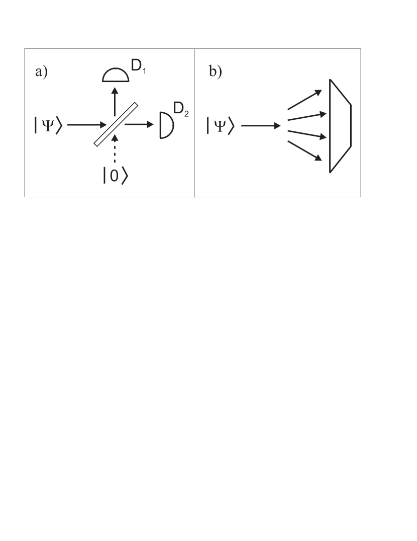
The POVM for the DDA consists of three elements, , and , corresponding to whether none, one, or both of the threshold detectors has detected at least one photon. (Note that we do not distinguish which of the two detectors has fired, as it does not provide any information about the input state.) This POVM is given by
| (4) |
Detector cascades can be designed to distribute the photons equally over modes using a multisplitter array and threshold detectors [12], but such a scheme becomes progressively more difficult to implement as increases.
2.2 Visible light photon counter
The VLPC [15, 16] functions differently than a threshold detector. The incoming mode is dispersed over many detector modes (active regions) that behave independently; see Fig. 1b. The VLPC can be modelled as a detector cascade using beamsplitters and finite efficiency threshold detectors. For the low photon numbers used in the KLM scheme, the probability of two or more photons entering the same active region is negligible; thus, one can use the approximation . The POVM for the VLPC consists of an infinite number of elements corresponding to detecting photons. This POVM is given by
| (5) |
For small , this POVM agrees with experimental tests of the VLPC [15, 17].
3 Nonlinear sign gate
Consider a quantum state of a radiation mode to be of the form
| (6) |
with . By interacting this mode with a Kerr medium, described by an interaction Hamiltonian [18]
| (7) |
the state is transformed as
| (8) |
For interaction time , the resulting transformation is a sign change ( phase shift) on the two–photon component.
Using only linear optics and photon counting, the nonlinear sign (NS) gate of KLM can implement this nonlinear transformation, albeit in a nondeterministic fashion. The design of the gate is presented in Fig. 2; see [19] for details.
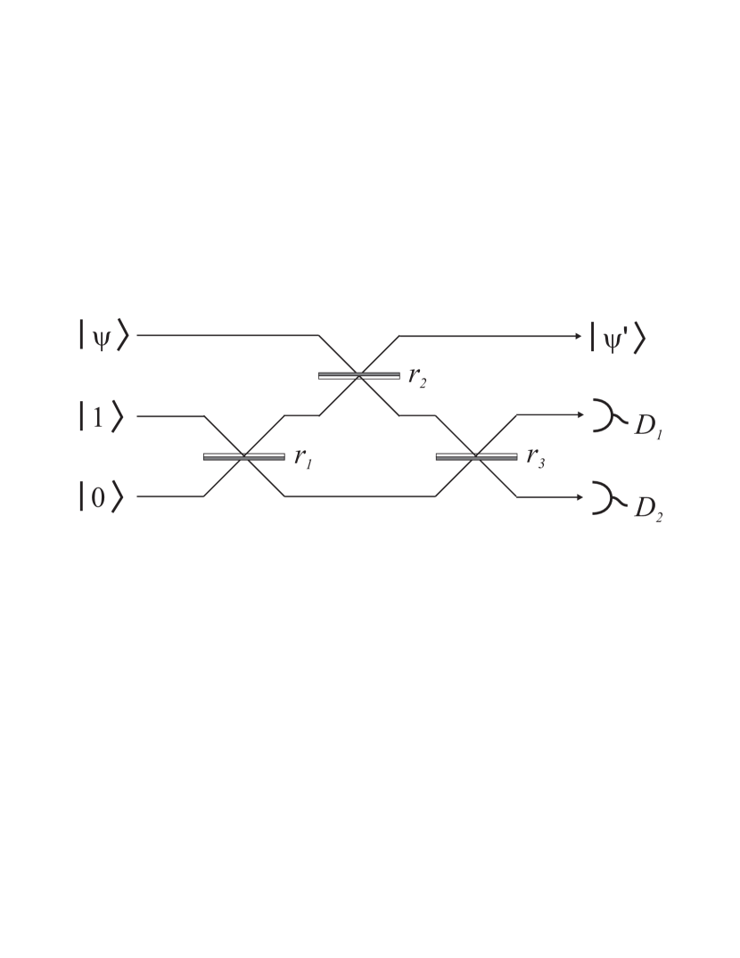
Two auxilliary modes are used; a single photon is injected into one, and the vacuum state into the other. If a single photon is detected at detector and no photon is detected at detector , the resulting transformation on the (unknown) input state is given by
| (9) |
The normalization factor of represents the fact that this transformation is achieved only one quarter of the time (the resulting state has square modulus ).
The NS gate requires photon counters that can discriminate the number of photons; the measurements must yield exactly one photon at detector and none at detector . With ideal photon counters described by the photon counting POVM of Eq. (1), the NS gate implements the transformation of Eq. (9). However, with either of the realistic photon counting schemes discussed in the previous section, the resulting transformation will be different. Photodetectors will miss events that should be kept, and they will also miscount photons and allow events that should be discarded. Thus, the output of the NS gate will be a mixed state which depends on the parameters of the photon counting measurements. In the following, we calculate the resulting mixed state output of an NS gate employing either of the photon counting schemes of the previous section.
3.1 NS gate using photon counting models
Notation is defined as follows. Let the input state enter mode , the single photon state enter mode and the vacuum enter mode . The three–mode state is passed through a sequence of three beamsplitters with intensity reflectivity , and respectively. The transformation given by these beamsplitters can be expressed in the form
| (10) |
where be the complex probability amplitude of photons exiting modes , respectively. Photon number measurements are performed on modes and , and the output state exits mode conditioned on a measurement of zero photons in mode and one photon in mode . The reflectivities are chosen to be
| (11) |
which gives and . Note that this condition gives (an additional simplification).
The other probability amplitudes for contributing Fock state outputs as functions of intensity reflectivities of the beamsplitters , and are
| (12) |
To calculate the (generally mixed) output state of a NS gate with a given detection scheme, one projects the three–mode state with the POVM elements for the detection of zero photons in mode and one photon in mode , then normalizes by the probability of this measurement. First, we consider a NS gate employing DDAs to perform the photon number measurements. A DDA, modelled by the POVM of Eq. (2.1), is placed at each of the output ports of modes and . The resulting unnormalized density matrix conditioned on a measurement of zero photons in mode and one photon in mode is given by
| (13) |
with unnormalized states
| (14) |
The trace of this density matrix is
| (15) |
This trace gives the probability of an apparent success; i.e., the probability of a measurement of zero photons at mode and one photon at mode . Note that “apparent success” is used; by that, we mean that the photon counters report zero and one photons respectively, although this does not imply that the gate has succesfully implemented the transformation (9). The normalized density matrix for this scheme is then given by
| (16) |
Using the VLPC to perform the photon measurements gives different results. The resulting unnormalized density matrix conditioned on a measurement of zero photons in mode and one photon in mode is given by
| (17) |
The trace of this density matrix gives the apparent success probability:
| (18) |
The resulting normalized density matrix for the VLPC–based scheme is thus
| (19) |
3.2 Fidelity and Gate Fidelity
With ideal photodetection, the output state of the NS gate is ; with the above photodetection models, the output is instead a mixed state given by Eq. (13) or (17). We can compare the desired outcome to these mixed states directly by employing the fidelity, which characterises the distinguishability of two states. Calculating the fidelity between a pure state and a mixed state is straightforward, and given by
| (20) |
We calculate the fidelity of the output states and for the DDA– and VLPC–based schemes, respectively. For simplicity, we calculate the fidelity of the unnormalized states, given by Eqs. (13) and (17), and then normalize the fidelity appropriately. For the DDA–based scheme, we find
| (21) |
and thus,
| (22) |
For the VLPC–based scheme, we find
| (23) |
and that the fidelity is given by
| (24) |
The gate fidelity [14] (specifically, for the NS gate discussed here) can be defined by the worst case scenario, i.e.,
| (25) |
The overlap for both detection schemes, as given by Eqs. (21) and (23), is minimised for any of the three Fock states , , or . The apparent success rate for both schemes, given by Eqs. (15) and (18), is maximised for the state . Thus, both photodetection models possess a gate fidelity determined by the input state , which corresponds to .
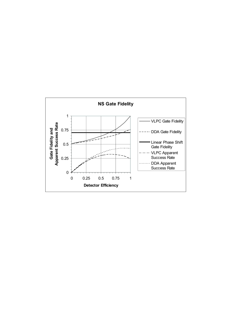
Fig. 3 gives a plot of gate fidelity as a function of detector efficiency for both the DDA– and the VLPC–based schemes. Also plotted are the apparent success rates of the gates. Note that, using ideal photon counting, the apparent success rate should be . This plot gives insight into why the gate fidelity is not unity: the increase in the apparent success over implies that the gate is reporting success when in fact it is performing incorrectly. Note that the DDA–based NS gate does not yield an apparent success rate of even for unit efficiency; this discrepency is due to the fact that a DDA cannot distinguish one from two photons.
3.3 Comparing the NS gate to a linear optics scheme
It is necessary to establish a benchmark for the gate fidelity, in order to determine the ability of the NS gate to perform a nonlinear transformation. One approach is to determine how such a NS gate compares with a gate that uses only linear optics. For example, consider the tranformation
| (26) |
This transformation is a linear phase shift, implemented using a phase shifter or a path–length delay. Although it does not implement the NS gate (due to the factor of on the term), it does a similar transformation and thus one can calculate the fidelity, comparing this output state to the desired NS output :
| (27) |
The gate fidelity for the linear phase shift is obtained (using the minimizing state with ) to be , and it can easily be shown that this gate fidelity is the maximum obtainable using linear optics alone. Thus, we can construct a gate with gate fidelity using only linear optics (specifically, a linear phase shift). This value sets a benchmark for any implementation of a NS gate: the gate fidelity must exceed in order to be considered a nonlinear gate.
Observing the plot of Fig. 3, it is seen that the NS gate fidelity using DDAs exceeds the threshold of for , whereas the VLPC–based scheme exceeds this threshold for .
4 Conclusions
As shown here, the function of a nondeterministic nonlinear gate (such as the NS gate) employing photon counting depends critically on the photon counting measurement model. The two photon counting schemes analyzed here, representing current technology, can only approximate an ideal photon counting measurement. As a result, the NS gate employing realistic detection schemes can only approximate the desired nonlinear transformation.
We have characterised the function of the NS gate with two realistic photon counting models by the gate fidelity, which describes the worst–case fidelity of an output state compared with the ideal output state, normalized to an apparently successful operation. With DDAs, the NS gate achieves a maximum gate fidelity of with unit efficiency detectors, and does not achieve the critical value of for realistic SPCM efficiencies. Thus, we conclude that a nonlinear transformation using a DDA–based NS gate cannot be achieved (although we note that adding more beamsplitters and SPCMs to form an array can increase the maximum gate fidelity). By comparison, the VLPC achieves a gate fidelity of one for unit efficiency, and performs well () for realistic VLPC efficiencies of [16]. Note, however, that the gate fidelity drops rapidly with efficiency less than one.
Performing nonlinear transformations using only linear optics and photon counting represents an exciting new paradigm for nonlinear quantum optics and quantum information. Current photodetection devices such as the VLPC can allow for nondeterministic nonlinear transformations to be performed using present technology. However, new and innovative photon counting schemes must be developed in order to meet the stringent requirements of fault–tolerant gates.
Acknowledgements.
This project has been supported by an Australian Research Council Large Grant. SDB acknowledges the support of a Macquarie University Research Fellowship and a Macquarie University New Staff Grant. ED acknowledges the support of a Stanford Graduate Fellowship.References
- [1] G. J. Milburn, “Quantum and classical Liouville dynamics of the anharmonic oscillator,” Phys. Rev. A 33, pp. 674-685, 1986.
- [2] B. Yurke and D. Stoler, “Generating quantum mechanical superpositions of macroscopically distinguishable states via amplitude dispersion,” Phys. Rev. Lett. 57, pp. 13-16, 1985.
- [3] V. Buzek and P. L. Knight, “Quantum interference, superposition states of light and nonclassical effects,” in Progress in Optics XXXIV, Ed. E. Wolf, pp. 1-159, North–Holland, Amsterdam, 1995.
- [4] I. L. Chuang and Y. Yamamoto, “Simple quantum computer,” Phys. Rev. A 52, pp. 3489-3496, 1995.
- [5] E. Knill, R. Laflamme and G. J. Milburn, “A scheme for efficient quantum computation with linear optics,” Nature (London) 409, pp. 46-52, 2001.
- [6] D. Gottesman and I. L. Chuang, “Demonstrating the viability of universal quantum computation using teleportation and single-qubit operations,” Nature (London) 402, pp. 390-393, 1999.
- [7] E. Knill, R. Laflamme and G. J. Milburn, “Thresholds for Linear Optics Quantum Computation,” http://arxiv.org/abs/quant-ph/0006120, 2000.
- [8] H. Lee, P. Kok, N. J. Cerf and J. P. Dowling, “Linear optics and projective measurements alone suffice to create large-photon-number path entanglement,” Phys. Rev. A 65, 030101(R), 2002.
- [9] W. Vogel and D.–G. Welsch, Lectures on Quantum Optics, Akademie Verlag, Berlin, 1994.
- [10] K. J. Resch, J. S. Lundeen and A. M. Steinberg, “Experimental observation of nonclassical effects on single-photon detection rates,” Phys. Rev. A 63, 020102(R), 2001.
- [11] S. D. Bartlett and B. C. Sanders, “Universal continuous-variable quantum computation: Requirement of optical nonlinearity for photon counting,” Phys. Rev. A 65, 042304, 2002.
- [12] P. Kok and S. L. Braunstein, “Detection devices in entanglement-based optical state preparation,” Phys. Rev. A 63, 033812, 2001.
- [13] S. Glancy, J. M. LoSecco, H. M. Vasconcelos, and C. E. Tanner, “Imperfect Detectors in Linear Optical Quantum Computers,” http://arxiv.org/abs/quant-ph/0201047, 2002.
- [14] M. A. Nielsen and I. L. Chuang, Quantum Computation and Quantum Information, Cambridge University Press, Cambridge, 2000.
- [15] J. Kim, S. Takeuchi, Y. Yamamoto and H. H. Hogue, “Multiphoton detection using visible light photon counter,” Appl. Phys. Lett. 74, pp. 902-904, 1999.
- [16] S. Takeuchi, J. Kim, Y. Yamamoto and H. H. Hogue, “Development of a high-quantum-efficiency single-photon counting system,” Appl. Phys. Lett. 74, pp. 1063-1065, 1999.
- [17] E. Waks, private communication.
- [18] D. F. Walls and G. J. Milburn, Quantum Optics, Springer, Berlin, 1994.
- [19] T. C. Ralph, A. G. White, W. J. Munro and G. J. Milburn, “Simple scheme for efficient linear optics quantum gates,” Phys. Rev. A 65, 012314, 2002.