A Compton Backscattering Polarimeter for Measuring Longitudinal Electron Polarization
Abstract
Compton backscattering polarimetry provides a fast and accurate method to measure the polarization of an electron beam in a storage ring. Since the method is non-destructive, the polarization of the electron beam can be monitored during internal target experiments. For this reason, a Compton polarimeter has been constructed at NIKHEF to measure the polarization of the longitudinally polarized electrons which can be stored in the AmPS ring. The design and results of the polarimeter, the first Compton polarimeter to measure the polarization of a stored longitudinally polarized electron beam directly, are presented in this paper.
keywords:
polarized Compton scattering, electron polarimetryPACS:
29.20.Dh, 29.27.Fh, 29.27.Hj, , , , and
1 Introduction
Stored polarized electron beams are now available at many laboratories. Such beams are produced either by radiative polarization[1, 2] of the stored beam or by injecting polarized electrons. Internal target experiments performed with such a beam require the electron polarization to be measured during the experiments. These measurements need to be done quickly, so that any changes in polarization can be accounted for, and parasitically, so that the measurement in no way affects the internal target experiment. One technique to do this is through the use of a Compton backscattering polarimeter.
In this technique, a circularly polarized photon beam is scattered off a polarized electron beam. Due to the asymmetry in the spin-dependent Compton scattering cross section, the polarization of the electron beam can be determined by changing the helicity of the photon beam. For transversely polarized electrons the asymmetry is measured with respect to the orbital plane of the electrons, while for longitudinally polarized electrons the asymmetry is measured in the energy-dependent cross section.
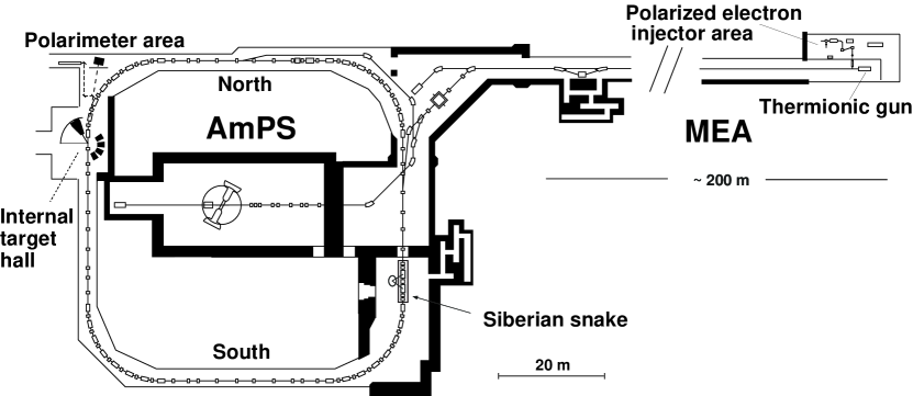
To perform spin-dependent electron scattering experiments, the MEA/AmPS facility at NIKHEF has been upgraded to provide a longitudinally polarized electron beam for internal target experiments[3]. An overview of the NIKHEF electron beam facility is shown in fig. 1. Polarized electrons are produced by a recently commissioned Polarized Electron Source (PES) [3], consisting of a laser driven photocathode electron source, a Z-shaped spin manipulator to orient the electron spin in any arbitrary direction, a Mott polarimeter to measure the electron polarization at the source, and a post-accelerator to match the energy of the polarized electrons to the acceptance of the chopper/buncher system of the linac(400 keV). After the post-accelerator, the polarized electrons are injected into the linear medium-energy accelerator (MEA) and accelerated up to 750 MeV. The electrons are then injected into the AmPS storage ring. Due to the low current produced by the polarized source, only a few mA can be stored per injection, but through the use of stacking a current of more than 200 mA has been stored in the ring. A Siberian Snake [4, 5] has been installed in the ring to preserve the polarization of the stored beam and to maintain a longitudinal orientation of the spin at the location of the internal target[6].
In this paper the performance of a laser backscattering polarimeter is presented, which was designed and constructed for the measurement of the longitudinal polarization of the stored electron beam in the AmPS ring. While many laboratories use Compton backscattering polarimeters to measure the polarization of stored transversely polarized electron beams[1, 7, 8], the present polarimeter was the first to measure the longitudinal polarization of a stored polarized electron beam[9].
In section 2, the physics of Compton scattering is discussed with emphasis on the energy range of the AmPS ring and on the technique for the measurement of longitudinal polarization. In section 3 the layout and the technical characteristics of the polarimeter are described, and in section 4 the results of the performance tests of the polarimeter are presented. Emphasis is put on the investigation of the systematic uncertainties of the polarimeter. Conclusions and a summary are given in section 5.
2 The Physics of Compton Scattering

The kinematics of Compton scattering in the lab frame is shown in fig. 2. The initial photon and electron energies are expressed as and , respectively, while the scattered photon energy is expressed as . The scattered electron is not shown. The positive z-axis is defined to be the direction of the incident electron. Unlike the kinematics of transversely polarized electrons, the reaction with longitudinally polarized electrons is symmetric about the azimuthal angle , and thus only the angle , between the incident electron and scattered photon, is shown. In the case of high-energy electrons, photons are backscattered in a narrow cone centered around the direction of the initial electron. Typical values of the scattering angle in the lab frame, corresponding to scattering in the electron rest frame, are given in table 1.
| 500 | 9.0 | 1.02 | 654 | 18.3 | 0.98 |
|---|---|---|---|---|---|
| 700 | 17.6 | 0.73 | 649 | 25.5 | 0.95 |
| 900 | 28.9 | 0.57 | 645 | 32.7 | 0.92 |
The polarization of the electron is specified in Cartesian coordinates by and that of the incident photon by the Stokes vector [10]. The amount of linearly polarized light is given by and that of circular polarization by . The sign of indicates the helicity of the polarization: for left-handed helicity () and for right-handed helicity (). For normalization of the Stokes vector is taken to be unity.
The cross section for Compton scattering of circularly polarized photons by longitudinally polarized electrons can be written as:
| (1) |
where is the circular-longitudinal spin correlation function and is the energy-differential cross section for unpolarized electrons and photons. This cross section and the spin correlation function are shown in fig. 3. Exact formula’s for these quantities can be found e.g. in refs. [11, 12, 13, 14].
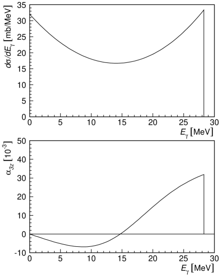
Equation 1 shows that an asymmetry measurement can be performed by switching the sign of which gives an asymmetry proportional with . For a given and this asymmetry can be written as,
| (2) |
where () is the polarized cross section with incident left-handed (right-handed) helicity, and .
The longitudinal polarization of the electron beam, , can be determined by taking the quantity as a free parameter while fitting the measured asymmetry with eq. 2. The photon polarization term, , needs to be measured independently.
Typical values of the total unpolarized Compton cross section, the maximum energy for backscattered photons, and the maximum value for the spin correlation function are given in table 1 for various electron beam energies that can be stored in the AmPS ring.
3 The NIKHEF Compton Polarimeter
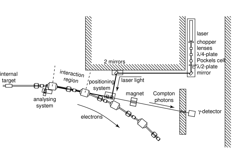
A schematic layout of the Compton polarimeter is shown in fig. 4. The polarimeter consists of the laser system with its associated optical system and a detector for the detection of the backscattered photons[15]. Laser photons interact with stored electrons in the straight section ( m long) after the first dipole (bending angle ) and before the second dipole after the Internal Target Facility (ITF). The distance of the Interaction Region (IR) from the internal target is 4.5 m.
The Siberian snake preserves the longitudinal spin direction at the ITF, but the orientation of the spin precesses in the ring, according to[16]
| (3) | |||||
| (4) |
where is the bending angle of the electrons and the precession angle of the spin. The polarimeter is only sensitive to the longitudinal component of the electron spin (see eq. 2). Therefore, the experimental asymmetry of the polarimeter reduces with . To minimize this reduction factor, the polarimeter has to be located close to the ITF. If for example the North or South straight (see fig. 1) would be used for the polarimeter (90∘ rotation from the ITF), the spin would be exactly transverse at = 440 MeV, and the reduction factor would be zero. On the other hand, because of the internal target at the ITF, the residual gas pressure in the 32 m long west straight can be orders of magnitude higher than in any other place in the ring, resulting in a large bremsstrahlung background. The section between the first and second dipole after the ITF has been chosen as a compromise between spin precession and bremsstrahlung background.
The backscattered photons leave the IR travelling in the same direction as the electrons of the beam and are separated from them by the second dipole. The -photons leave the vacuum system via a vacuum window and pass through a mirror of the optical system, a sweeping magnet, and a hole in a concrete shielding wall to the gamma detector.
3.1 The laser and the associated optical system
An Innova 100-25 Ar-ion laser system111Coherent Benelux, Argonstraat 136, 2718 SP Zoetermeer, The Netherlands is used which can provide a 10 W continuous beam. The wavelength of the laser light is = 514 nm, the divergence 0.4 mrad (full angle), and the diameter 1.8 mm. The initially linearly polarized light is converted to circularly polarized light with an anti-reflection coated -plate. Left- and right-handed light is obtained by switching the high voltage on a Inrad 214-090 Pockels cell222Inrad, 181 Legrand Avenue, Northvale, NJ 07647, USA, positioned after the -plate, see fig. 4. The Pockels cell switches between zero-wave (if high voltage is off) and half-wave (if high voltage is on) retardation. The polarization of the laser light is better than 99.8% directly after the Pockels cell. We have observed a small degradation along the beam path, but the degree of polarization is well above 95% at the IR if the system is tuned carefully. After the first tests with a polarized electron beam (see section 4), we have added a -plate to our system, which reverses the sign of the laser polarization while keeping all steering signals and the high voltage on the Pockels cell constant. The -plate can be moved into the optical path by means of a compressed air driven translation stage and is located directly after the Pockels cell. It has been used to investigate false asymmetries (see section 4).
To facilitate the transport of the laser beam and in order to prevent the Pockels cell from damage by high intensity light, a Galilean expander consisting of two lenses is placed in front of the -plate. The focal lengths of the lenses are -2.5 cm and 8.0 cm with almost coinciding focal points. This results in an expansion of the laser beam by a factor 3.2 and a reduction of the divergence by the same factor. The focal point of the expander is placed in the IR. The lenses are diffraction-limited and have anti-reflection coatings optimized for 514 nm.
In order to protect both the Ar-ion laser and the Pockels cell from radiation damage they are installed in a niche in the NW-curve of AmPS. The laser light is guided to the IR, over a total path of approximately 12 m, by a system of six dielectric mirrors. All mirrors are optimized for 90∘ scattering at 514 nm. The first mirror reflects the beam from the niche in the direction of ITF. A set of two mirrors reflects the beam into the beam positioning system. Two mirrors are used at this location in order to account for the 11.25∘ bend caused by the first dipole after ITF, while maintaining 90∘ reflections on all mirrors.
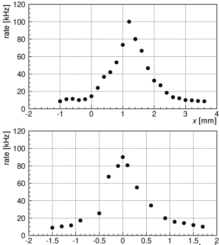
The positioning system consists of two mirrors connected to two translation stages and a gimbal mount. Both translation stages and the gimbal mount can be controlled with DC-motors. The positioning system gives full control over both angle and position of the laser beam in all directions and is used to optimize the overlap of the electron and laser beam. Initial alignment was done manually, centering it on the entrance and exit vacuum windows of the IR. The final alignment of the laser beam is performed with the DC-motors, while electrons are circulating in AmPS. The laser is aligned by optimizing the rate of backscattered photons, see fig. 5. A sixth mirror is used to reflect the beam into the IR.
The laser beam enters and leaves the IR via Kodial ND-40 CF-F vacuum windows333Balzers-Pfeiffer GmbH, Postfach 1280, D-35608 Asslar, Germany (diameter 25 mm). A system of two mirrors reflects the beam into a beam analysis system after the second vacuum window. It consists of a power meter, a linear polarizer, and -plate. The polarizer and -plate are mounted on a motorized translation stage and can be taken out of the beam path to measure the total transported laser power. When the -plate and polarizer have been inserted into the beam, the -plate can be rotated with a DC-motor and the laser polarization can be determined by measuring the power as a function of the orientation of the -plate. Laser beam polarization measurements done with the beam analysis system are only used as a monitor of the system. The polarization used in the extraction of the electron polarization from an asymmetry measurement is measured manually immediately before and after the vacuum windows of the IR. This ensures the absence of systematic errors introduced by the two mirrors between the second vacuum window and the beam analysis system.
A chopper mounted immediately after the laser is used to block the laser light for of the time to measure the background. The chopper, operating at a frequency of 75 Hz, is also used to generate the driving signal for the Pockels cell. This ensures that the background measurement and the flipping of the laser polarization have exactly the same frequency.
The small fraction of the laser light transmitted through the mirrors is utilized to monitor the position of the laser beam using camera’s which are located directly before and after the IR.
3.2 The gamma detector
The gamma detector of the polarimeter, situated 12 m downstream of the IR, must be capable of detecting -rays with an energy of up to 30 MeV (see table 1), handling rates up to 1 MHz, and be radiation resistant. Total absorption shower counters made of dense inorganic scintillating crystals were chosen.
For the commissioning experiments with an unpolarized stored electron beam a cylindrical BGO scintillator crystal (102 mm diameter and 100 mm long), optically coupled to a Hamamatsu R1250 photomultiplier444Hamamatsu Photonics Deutschland GmbH, Arzbergerstr. 10, D-8036 Herrsching am Ammersee, Germany was used to test and tune our laser positioning system. A disadvantage of BGO crystal is the long decay time (300 ns) of the scintillation light which limits the maximum rate.
The BGO crystal was later replaced by a rectangular ( cm3) pure CsI crystal. This crystal was optically coupled to a XP4312/B photomultiplier555Philips Photonics, BP 520, F-19106 Brive, France. Due to the small decay time of the pure CsI crystal (35 and 6 ns), an active base on the photomultiplier tube, and dedicated electronics, the total setup is able to handle rates up to 1 MHz. A 10 cm thick lead cylinder surrounds the scintillator crystal for shielding purposes. A plastic scintillator (NE102) placed in the front of the gamma detector can be used to veto charged particles.
3.3 The Control and the Data Acquisition System
The optical system is controlled with a computer code developed with LabVIEW666National Instruments, 6504 Bridge Point Parkway, Austin, TX 78730-5039, USA on a SUN-workstation, see fig. 6. The communication between the workstation and the optical system is realised via GPIB (IEEE-488.2), which is connected to the workstation via Ethernet. The four DC-motors used for the steering of the laser beam are controlled by a PI804 motor controller777Physik Instrumente GmbH, Polytec-Platz 5-7, D-76333 Waldbronn, Germany. A resolution of 2 m and 60 rad can be obtained with the PI804 and the DC-motors. Control signals for the movement of the -plate after the Pockels cell, and of the -plate and translation stage of the beam analysis system are also generated in the PI804.
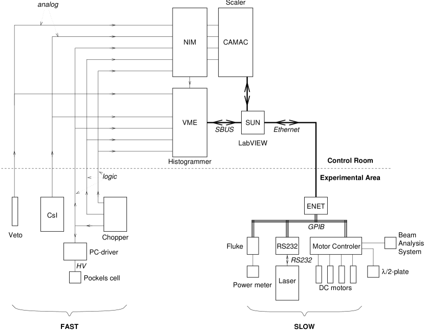
The data acquisition is done with a single VME-module, designed and constructed at NIKHEF. The module accepts the analog output of the photomultiplier connected to the gamma detector and digitises this signal using an 8-bit flash ADC. Furthermore, it accepts logic signals representing the state of the chopper and the Pockels cell. Based on those signals, the module constructs four separate energy spectra, for laser blocked or not and for left and right circularly polarized light. The maximum rate the module can handle is 2.5 MHz. The energy spectra are read out typically every 30 s. The VME-module can generate its own trigger for the ADC or it can accept an external trigger. When the external trigger is used, more sophisticated triggering systems can be made, while the internal trigger makes any external logic modules superfluous, resulting in a very compact system. An extra advantage of the external trigger circuit is the possibility to connect the trigger not only to the VME-module, but also to a scaler. The scaler information can then be used for the optimization of the electron and laser beam overlap and to determine dead-time corrections for all energy spectra. Both modes of operation have been used.
Determining the electron polarization from the energy spectra is done via eq. 2. All energy spectra are normalized to their integrated luminosities, taking into account dead-time effects and measuring times. Background spectra are subtracted, after which the experimental asymmetry () is constructed, via:
| (5) |
where () are the energy spectra for left (right) polarized laser light, after normalisation and background subtraction. The experimental spin correlation function is obtained with Monte Carlo simulations, performed with the computer code GEANT[17], taking into account the electron and laser beam phase space along the IR and the characteristics of the gamma detector. is measured separately and is calculated from the electron beam energy. is extracted from via a fit with eq. 5 with as a free parameter. The results of the Monte Carlo simulations have also been used for the energy calibration of the gamma detector.
4 The performance of the polarimeter
The polarimeter has been tested with polarized electrons at a low beam current of appr. 5 mA. These preliminary tests were the first direct measurements of longitudinal polarization in an electron storage ring. They are described in section 4.1. The accuracy of the electron polarization enters directly in the accuracy of all experiments performed with the polarized electron beam. Therefore, it is of the utmost importance that the statistical and systematic uncertainty in is small and well known. Statistical accuracy of 1% can be obtained in 1500 s and will not influence the accuracy of the internal target experiments significantly. We have performed extensive investigations of the systematic uncertainty of the polarimeter, in order to minimize and understand these errors. The results of these investigations are presented in section 4.2. Finally, the polarimeter has been used to monitor the electron polarization during the first internal target experiment at NIKHEF that made use of the polarized beam. This is presented in the last paragraph of this section.
4.1 Preliminary tests
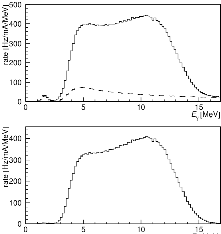
Preliminary tests with a polarized electron beam have been done with a beam current of 2–5 mA and 3 W laser power, to avoid rate problems in the gamma-detector and to minimize the contribution of background events. Because of the extremely low current in the accelerator and a very poor injection efficiency, multiple injections were stacked to obtain the beam current mentioned. The electron energy was 615 MeV, resulting in backscattered photons with a maximum energy of MeV. 88% of all detected photons originated from Compton scattering, with a rate normalized to the beam current of 3.5 kHz/mA, see fig. 7.
The polarization of the electrons was measured with the Mott polarimeter, located between PES and MEA, to be 0.41. The orientation of the electron spin at the injector was not optimized for maximum polarization in AmPS, reducing the polarization in AmPS to 0.39888The difference in the polarization as measured with the Mott polarimeter cited in [9] originates from a recalibration of the Mott polarimeter[18]..
During the experiment, an energy shift was observed between the energy spectra for left- and right-handed polarized laser light, due to ground currents (see next section). This shift of 22 keV ( of the full scale) was corrected. The asymmetry was measured and the electron polarization extracted, see fig. 8. In the extraction of the electron polarization, we only used the values of measured in the energy range from 5 to 14 MeV. The lower limit of the range is determined by the energy threshold of the detector. As the energy shift described above occurs before the trigger is applied, the asymmetry gets a systematic offset at the threshold (see the lowest points in fig. 8). The upper limit is chosen such that the real to background ratio is better than 4:1, to avoid sensitivity to the background subtraction.
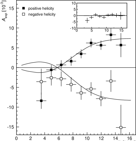
We measured () for electrons with positive (negative) helicity. These numbers are in good agreement with the result from the Mott polarimeter. We also determined for unpolarized electrons and found , indicating the absence of false asymmetries in our measurements. This first result obtained with the Compton polarimeter proves that it is possible to accelerate polarized electrons and inject them in a storage ring, even if stacking is required. It also shows that it is possible to operate a Compton polarimeter to determine the absolute degree of polarization of a longitudinally polarized stored electron beam.
4.2 Systematic checks
We have performed a series of measurements to investigate the systematic errors of the polarimeter. False asymmetries result in errors on the determination of the electron polarization. Possible sources of false asymmetries are: a) inaccuracies in the ratio of the integrated luminosities for the two laser polarization states; b) inaccuracies in the determination of the background contribution, and; c) any signal in phase with the asymmetry measurement. The first type of false asymmetry will give a energy-independent contribution, while type b will depend on . Type c can either be energy dependent or independent, based on how the signal influences the asymmetry measurement.
During these measurements, the storage ring could only be operated with a 10% partial snake[19]. Therefore, it was necessary to perform all measurements at an electron beam energy of 440 MeV, resulting in a maximum energy for the Compton photons of 7.0 MeV. This beam energy is lower than the design specification of the polarimeter (500–900 MeV), resulting in a poor energy resolution. To reduce background at this rather low energy, we performed all measurements with beam currents smaller than 15 mA, resulting in Compton rates 120 kHz (8.0 kHz/mA). An advantage of the low beam energy for our measurements is an enhanced sensitivity for false asymmetries, because of the relatively small Compton asymmetry (see table 2). The polarization measured with the Mott polarimeter was 0.69. The settings of the Z-shaped spin manipulator were optimized for maximum polarization in the AmPS ring[20].
| source of systematic error | |
|---|---|
| calibration | 0.022 |
| 0.013 | |
| parametrisation | 0.004 |
| 0.003 | |
| Energy spectrum shift | 0.001 |
| Luminosity asymmetry | 0.001 |
| Total | 0.027 |
The measurements showed an energy-independent asymmetry of the order of . It disappeared if we disabled the switching of the Pockels cell. After we switched the Pockels cell the rate changed of the order of 10% in 10 s, and then stabilized. If we moved the laser beam by 0.1 mm simultaneously with the switching of the Pockels cell, the equilibrium rate was the same for both states. From this, we concluded that the Pockels cell is heated by applying the high voltage. The effect is a small steering of the laser beam, in the order of 10 rad between the two equilibrium states, or 15 nrad during normal operation, resulting in a false asymmetry of type a. The exact value of this false asymmetry changed over the time of days, though the order of magnitude was constant. It can be explained by temperature drifts of the laser, because the size of the false asymmetry depends strongly on the exact position of the laser beam with respect to the electron beam.
False asymmetries from inaccuracies in the background contributions are negligible, because of the good real to background ratio in the energy range used for the polarization measurements. Furthermore, the background has to be related to the laser polarization in order to introduce false asymmetries. In the energy range used, no physics process can contribute significantly to the asymmetry. The background subtraction could also introduce an error in the size of the asymmetry, if the background subtraction was not performed accurately. Also this effect is negligible, because we measured the background simultaneously, the background is small compared to the real signal, and we correct all energy spectra for dead-time effects.
The only signal in phase with the asymmetry measurements is the driving signal of the Pockels cell and electronics. We have observed a false asymmetry of the order of , related to the driving signal of the Pockels cell and electronics. It is proportional to the derivative of the energy spectrum. This indicates that the signal from the gamma detector is shifted by the driving signal of the Pockels cell, before digitisation. This can happen either between the detector and the electronics, or inside the VME-module. The asymmetry disappears if we generate the driving signals for the electronics separately, indicating that the shift of the analog signal happens before the signal reaches the electronics. This is confirmed by the fact that the false asymmetry also disappears if the signal from the gamma detector is disconnected from the electronics. The shift of the analog signal results in a shift of the energy spectrum of the order of of the full energy scale.
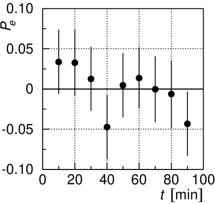
Both false asymmetries mentioned above can be corrected for, if they are known during real polarization measurements. Therefore, we have performed all measurements in sets of six. Three measurements were done with different electron polarizations injected into the ring (positive helicity, unpolarized and negative helicity). These measurements were repeated with the -plate inserted in the path of the laser beam, which reverses the sign of the measured Compton asymmetry by a change of sign of the laser polarization. The measurements with unpolarized electrons were used to determine the false asymmetries. This is only valid, if the false asymmetries do not change on the time scale of the 2 times 3 measurements. To check this, one measurement of such a set was repeated nine times. To exclude sensitivity to variations in the polarization of the injected electrons or spin life time, we choose to use unpolarized electrons. The total measurement time was appr. 90 minutes., while a full set of six measurements normally takes about 60 minutes. The results are shown in fig. 9 and show good stability on this time scale, indicating that we can use measurements with unpolarized electrons to correct for false asymmetries.
The systematic uncertainty of the polarimeter is not only determined by false asymmetries, but also by the analysis parameters. The main contribution comes from the energy calibration of the detector. Smaller effects come from the uncertainty in the energy of the electron beam, the laser polarization and the parametrisation of the theoretical analysing power, folded with the parameters of the detector, like the energy resolution. The laser polarization measured is the average polarization of the whole laser beam. The laser beam is larger than the electron beam and therefore only its central part interacts with the electrons. We have measured the laser polarization in a range of transverse positions and did not observe any variation.
Table 2 shows an overview of all sources of systematic errors for electrons of 440 MeV with a polarization of 0.60. The systematic error will decrease for higher beam energy, because the Compton asymmetry increases.
4.3 Polarization monitoring
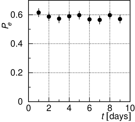
During the first data run of experiment 94-05 [21], the polarimeter has been used to monitor the polarization of the electrons stored in the AmPS ring. This data run followed immediately after the measurements described in the previous section. These measurements were also performed with a partial snake at a beam energy of 440 MeV. The polarization could not be measured simultaneously with the experimental data taking, because the background rate due to 3He gas leaking into the IR from the internal target was too high. Therefore, the electron polarization was measured once a day when no gas was fed into the internal target.
The long-term stability was investigated from these measurements. They are sensitive not only to variations of the polarimeter, but also to any other time-dependent effect such as a degradation of the photo-cathode used at PES. No trend is observed in the polarization of the electrons (see fig. 10), indicating a good long-term stability for all components, including the polarimeter.
The average polarization for all measurements and for negative and positive electron helicity determined with the -plate in (out) the laser beam was measured to be (). This is less than the value measured with the Mott polarimeter (0.69). No polarization loss was observed during the first measurement at 615 MeV (see section 4.1). The difference between the two measurements were the beam energy, the settings of the snake, and the orientation of the spin in the accelerator.
The beam energy has no direct effect on the depolarization in the accelerator. Depolarization can occur in the focussing solenoids in the first sections of the accelerator. Small energy differences of the electrons can cause differences in the spin precession in the lenses, which will result in loss of coherence of the transverse component of the electron spin. At 615 MeV the spin was longitudinal in the accelerator and thus was not sensitive for this effect. The electron spin in the measurements at 440 MeV was completely transverse and so had maximum sensitivity for depolarization due to the lenses.
The difference might also be explained by polarization losses during injection, due to the partial snake. A full snake ensures that the spin tune is 0.5, so that all possible spin resonances are far away. The spin tune with the partial snake was 0.05. If this was close to a depolarizing resonance, it is possible that during injection the spin life time is shorter due to larger synchrotron oscillations and so cause a loss of polarization during the damping of the beam. We have measured the spin life time of the damped beam, to be well over 3600 s which can not explain the losses we have observed.
5 Summary - Conclusions
We have successfully designed, constructed, and operated a Compton polarimeter to measure the longitudinal polarization of a stored electron beam. We have measured the polarization of a stored beam at beam energies of 440 MeV and 615 MeV. The absolute systematic uncertainty has been determined to be 0.027 for electrons at 440 MeV with a polarization of 0.60. The systematic uncertainty will decrease at higher beam energies. It has been shown that the polarimeter can be operated routinely and reliably during the first experiment at the internal target facility that made use of polarized electrons. Extra pumping capacity will be installed in the future to make polarization measurements possible during operation of an internal target.
References
- [1] D. P. Barber et al., Nucl. Instr. Meth. Phys. Res. A329 (1993) 79.
- [2] L. Knudsen et al., Phys. Lett. B270 (1991) 97.
- [3] Y. B. Bolkhovityanov et al., The polarized electon source at NIKHEF, in Proc. of the International Symposium on High Energy Spin Physics, edited by C. W. de Jager et al., pages 730–732, World Scientific, 1996.
- [4] Ya. S. Derbenev and A. M. Kondratenko, Sov. Phys.-JETP 37 (1973) 968.
- [5] Ya. S. Derbenev and A. M. Kondratenko, Sov. Phys.-Dokl. 20 (1975) 830.
- [6] C. W. de Jager, V. Ptitsin and Yu. M. Shatunov, Radiative electron polarization in the AmPS storage ring, in Proc. of the International Symposium on High-Energy Spin Physics, edited by C. W. de Jager et al., pages 555–557, World Scientific, 1996.
- [7] D. P. Barber et al., Nucl. Instr. Meth. Phys. Res. A338 (1994) 166.
- [8] M. Placidi and R. Rossmanith, Nucl. Instr. Meth. Phys. Res. A274 (1989) 79.
- [9] I. Passchier et al., A Compton backscattering polarimeter for electron beams below 1 GeV, in Proc. of the International Symposium on High-Energy Spin Physics, edited by C. W. de Jager et al., pages 807–809, World Scientific, 1996.
- [10] U. Fano, Optical Society of America 39 (1949) 859.
- [11] C. Itzykson and J. Zuber, Quantum Field Theory, McGraw-Hill Inc., 1980.
- [12] R. C. Fernow, Introduction to Experimental Particle Physics, Cambridge University Press, 1986.
- [13] F. W. Lipps and H. A. Tolhoek, Physica 20 (1954) 85.
- [14] H. A. Tolhoek, Rev. Mod. Phys. 28 (1956) 277.
- [15] N. P. Vodinas et al., Electron beam polarimeter, in International Workshop on Polarized Beams and Polairzed Targets, edited by Hans Paetz gen. Schieck and Lutz Sydow, pages 328–332, World Scientific, 1996.
- [16] Bryan W. Montague, Phys. Rep. 113 (1984) 1.
- [17] GEANT team, GEANT - Detector Description and Simulation Tool, CERN Geneva, Switzerland, version 3.21.
- [18] B. L. Militsyn, private communication.
- [19] C. Ohmori et al., Phys. Rev. Lett. 76 (1996).
- [20] H. J. Bulten et al., Phys. Rev. Lett. (1998), to be submitted.
- [21] R. Alarcon et al., NIKHEF proposal 94-05, 1994, spokesman: J. F. J. van den Brand.