A Compton Backscattering Polarimeter for Measuring Longitudinal Electron Polarization
Abstract
Compton backscattering polarimetry provides a fast measurement of the polarization of an electron beam in a storage ring. Since the method is non-destructive, the polarization of the electrons can be monitored during internal target experiments. At NIKHEF a Compton polarimeter has been constructed to measure the polarization of the longitudinally polarized electrons stored in the AmPS ring. First results obtained with the polarimeter, the first Compton polarimeter to measure the polarization of a stored longitudinally polarized electron beam, are presented in this paper.
Introduction
The NIKHEF Compton polarimeter has been constructed to measure the longitudinal polarization of electrons stored in the AmPS ring. The polarized electrons are provided by a recently commissioned polarized electron source (PES) cbp:bol96 . While Compton backscattering polarimeters are used to measure the polarization of transversely polarized stored electron beamscbp:pla89 ; cbp:bar93 , NIKHEF’s detector was the first to measure the polarization of a longitudinally polarized stored beamcbp:igo96 .
In this technique, a circularly polarized photon beam (polarization , energy ) is backscattered from a stored polarized electron beam (polarization , energy ).
The cross section for Compton scattering of circularly polarized photons from longitudinally polarized electrons can be written as
| (1) |
where follows from the energy spectrum for unpolarized electrons and photons and represents the longitudinal component of the electron polarization. For a given and the asymmetry can be written as,
| (2) |
where () is the number of photons with energy with incident left (right) handed helicity, and is the difference between the two polarization states, divided by two. is determined by taking as a free parameter and fitting the measured asymmetry with eq. 2. The relation between and is determined by the lattice of the storage ring.
Layout of the polarimeter
A schematic layout of the Compton polarimeter is shown in fig. 1. The polarimeter consists of a laser system with its associated optical system and a detector for the detection of backscattered photons.
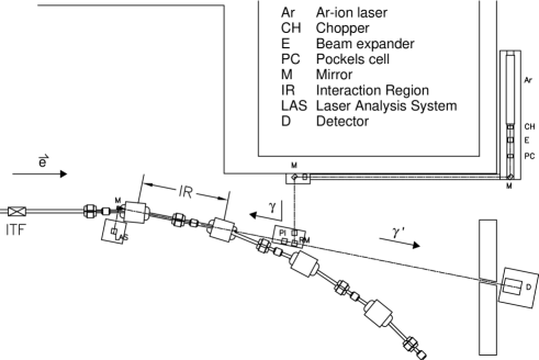
Laser photons are produced by a 10 W CW Ar-ion laser, operated at 514 nm. Part of the mirrors in the optical path can be controlled remotely, in order to optimize the overlap of the electron and laser beam. A quarter-wave plate is used to convert the initially linearly polarized photons to circularly polarized. A Pockels cell is used to switch the helicity between left and right, while a half-wave plate can be inserted in the optical path to check for false asymmetries by reversing the sign of the Compton asymmetry.
Laser photons interact with stored electrons in the straight section (length m) between the first dipole and second dipole (bending angles ) after the internal target facility. The backscattered photons leave the interaction region traveling in the same direction as the electrons of the beam and are separated from them after the second dipole. They are detected in a gamma detector, consisting of a block of mm3 pure CsI.
A chopper mounted immediately after the Ar-ion laser is used to block the laser light for of the time for background measurements. The chopper is operated at 75 Hz and also generates the driving signal for the Pockels cell.
Results
The storage ring could only be operated with a 10% partial snakecbp:ohm96 . Therefore, it was necessary to perform all measurements with an electron beam energy of 440 MeV, resulting in a maximum energy for the Compton photons of 7.04 MeV. This energy is lower than that of the design specification (500–900 MeV), resulting in a poor energy resolution. To reduce background at this rather low energy, we performed all measurements with beam currents smaller than 15 mA. The rate of backscattered photons was in the order of 8 kHz/mA at full laser power, in agreement with simulations.
To minimize the effects of false asymmetries (induced by a small steering effect of the Pockels Cell), we performed sets of six independent measurements to determine the electron polarization. Three measurements were done with different electron polarizations injected into the ring (positive helicity, unpolarized and negative helicity). These measurements were repeated with the half-wave plate of the polarimeter inserted in the optical path. The measurements with unpolarized electrons were used to determine and correct for false asymmetries, while the insertion of the half-wave plate was done as a consistency check. Figure 2 shows the asymmetry before and after correction for false asymmetries.


To determine the stability of the polarimeter, one measurement was repeated nine times. To exclude any sensitivity to variations in the polarization of the injected electrons or spin life time, those measurements were performed with unpolarized electrons. The total measurement time was 90 min, while a full set of six measurements normally takes about 60 min. The results are shown in fig. 3 and show good stability on this time scale.


The long-term stability is determined from polarization measurements done typically once a day. These measurements are sensitive not only to variations of the polarimeter, but also to any other time-dependent effect such as a degradation of the cathode used at PES. The results (see fig. 3) show no trend in the polarization of the electrons, indicating a good long-term stability for all components.
The polarimeter has been used successfully to optimize the settings of the Z-manipulator at PES. After the optimization, the spin life time () and initial polarization () has been determined by combining the data of nine measurements of six minutes each. The combined data have been rebinned as a function of time and the polarization has been determined for each bin separately. We found , and . The spin life time is in agreement with our calculations. The polarization measured with the Mott polarimeter at PES was . The difference between the polarization measured by the Mott polarimeter and by the Compton polarimeter may be caused by depolarization due to the focusing solenoids in the linac or depolarizing resonances during damping of the beam.
Conclusions
Here, we describe the results of extensive tests done with a Compton backscattering electron polarimeter. The tests have been performed at an electron energy of 440 MeV and a partial snake. The results show that it is possible to operate the polarimeter in a reliably manner over a period of weeks. Furthermore, the polarimeter has been used to map out the full dependence of the electron polarization of stored electrons on the settings of the Z-manipulator, and to determine the spin life time and depolarization during acceleration and injection of the electrons.
Acknowledgment
This work was supported in part by the Stichting voor Fundamenteel Onderzoek der Materie (FOM), which is financially supported by the Nederlandse Organisatie voor Wetenschappelijk Onderzoek (NWO), the Swiss National Foundation, the National Science Foundation under Grants No. PHY-9316221 (Wisconsin), PHY-9200435 (Arizona State) and HRD-9154080 (Hampton), Nato Grant No. CRG920219. and HCM Grant Nrs. ERBCHBICT-930606 and ERB4001GT931472.
References
- (1) Y. B. Bolkhovityanov et al., The polarized electon source at NIKHEF, in Proc. of the International Symposium on High Energy Spin Physics, edited by C. W. de Jager et al., pages 730–732, World Scientific, 1996.
- (2) M. Placidi and R. Rossmanith, Nucl. Instr. Meth. Phys. Res. A274 (1989) 79.
- (3) D. P. Barber et al., Nucl. Instr. Meth. Phys. Res. A329 (1993) 79.
- (4) I. Passchier et al., A Compton backscattering polarimeter for electron beams below 1 GeV, in Proc. of the International Symposium on High-Energy Spin Physics, edited by C. W. de Jager et al., pages 807–809, World Scientific, 1996.
- (5) C. Ohmori et al., Phys. Rev. Lett. 76 (1996).