Simulation of Pickup Signal in a Resistive Plate Chamber
1/AF Bidhannagar, Kolkata - 700064
nayana.majumdar@saha.ac.in, supratik.mukhopadhyay@saha.ac.in, sudeb.bhattacharya@saha.ac.in)
Abstract
The signal induced by an electron on a pickup strip has been calculated in a RPC used in INO calorimeter [1] following Ramo’s theorem [2]. An accurate estimation of weighting field has been obtained using a nearly exact Boundary Element Method (neBEM) solver [3] while the electron velocity from the real field values. The calculation has shown a growth and subsequent fall of pickup signal with duration about ps.
1 Introduction
The resistive plate chamber (RPC) has become an integral part of modern high energy experinments owing to its simple design and construction, good time resolution, high efficiency and low cost production. Several problems like inherent rate limitation and much debated space charge effect have induced various studies on detailed simulation of RPC signals considering different physics and electronics aspects.
The induction of signal in the electrodes of a chamber can be treated by Ramo’s theorem following which the electrostatic and weighting fields turn out to be two fundamental quantities. In general, instead of carrying out detailed computation for realistic RPC geometries of severl layers of dielectrics, the weighting potential and field of a RPC is determined for a simpler geometry of three layers for which 2D analytic solutions can be derived [4]. A thorough study on the 3D field distribution is required for realistic configuration of a RPC in order to achieve a true estimation of the induced signal. The field computation is usually carried out using commercial Finite Element Method (FEM) packages, although, it is known to yield poor accuracy despite of rigorous computation. A precise computation of 3D field distribution has been carried out using a nearly exact Boundary Element Method (neBEM). In this formulation, many of the drawbacks of the standard BEM like singularities and near-field inaccuracies could be removed due to use of analytic solutions of potential and field. A simple calculation of induced signal due to the motion of an electron in the chamber volume has been carried out with precise computation of 3D weighting and actual field for actual geometry of an RPC to be used in INO calorimeter.
2 Signal Induction Process
According to Ramo’s theorem, the current induced due to a charge cluster moving with a drift velocity can be evaluated as follows:
| (1) |
where is the weighting field at associated with the electrode under study. It may be mentioned here that the weighting field can be obtained when readout electrode is set to V keeping all other electrodes grounded.
3 Results and discussions
3.1 Comparison with analytical solutions
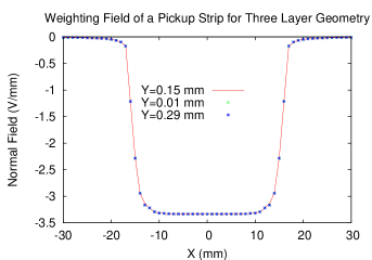
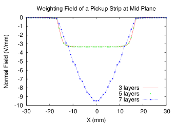
The results obtained for three layer INO RPC following analytic solutions and neBEM calculations have been illustrated in fig. 1(a) for three different positions along the axis of the geometry. The analytic expressions have been found to be valid up to two more resistive layers. However, inclusion of further layers has brought in a significant change (see fig.1(b)) indicating that the naive use of analytic expressions may lead to non-negligible errors.
3.2 Comparison with other methods
The solver has been validated by computing the electrical properties of a configuration containing two layers of dielectrics with a thin layer of graphite on each outer side to provide high voltage.
| Location | FEM | DBEM | NEBEM |
|---|---|---|---|
| 18.0,3.0 | 0.1723103 | 0.17302 | 0.1740844 |
| 4.0,9.0 | 0.2809692 | 0.27448 | 0.2807477 |
| 25.0,16.0 | 0.6000305 | 0.59607 | 0.5991884 |
| 5.0,17.0 | 0.679071 | 0.67492 | 0.6785017 |
3.3 Calculation for INO RPC
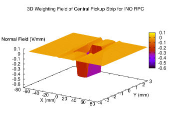
A glass RPC with glass and gas thickness of mm has been considered. A thin graphite coating of thickness m has been provided with a high voltage of KV. The readout strips are separated from the graphite layers by a PET film, m thick. Five readout strips in X-direction have been considered with thickness m, width cm and pitch mm while the Y-readout has been considered to be an uniform plate of same thickness. The length of the chamber in Z-direction has been made cm. However the inclusion of PET film above the graphite layer has been found to generate some numerical instability and excluded afterwards. The dielectric constants of glass, graphite and gas layers have taken to be (float glass), and (Argon) respectively. The results of the weighting and real field distributions have been shown in fig.2(a) and (b).

3.4 Calculation of induced signal
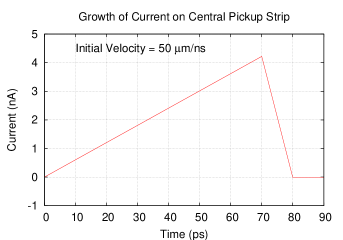
The induced current has been calculated at intervals of ps during the passage of the electron in the gas gap. The electron has been assumed to pass perpendicularly across the detector plane at its center with a velocity m/ns [6] starting from an initial position m above the lower glass layer. The weighting field has been evaluated at each position of the electron due to the central readout strip while the velocity has been determined from the real field using neBEM. The result is plotted in fig.3 which has shown the growth of the signal while electron has moved in the gas gap and a subsequent fall as the electron has left the gap.
4 Conclusion
Using the neBEM solver, the three dimensional weighting potential and field can be calculated precisely even for a very detailed geometry of a RPC. This allows us to simulate the induced current on any electrode of a RPC due to the passage of an ionizing particle. The drift velocity of the particle can be calculated using GARFIELD. However, the inclusion of several very thin layer of dielectrics has been found to generate numerical instabilities for which the solver would have to be optimized.
References
- [1] INO Collaboration, INO Project Report, INO/2006/01 (2006)
- [2] S. Ramo, Proc. IRE 27, p.584 (1939)
- [3] N.Majumdar, S. Mukhopadhyay, Nucl. Instr. Meth. Phys. Research, A 566, p.489 (2006)
- [4] T. Heubrandtner et al., Nucl. Instr. and Meth. A 489, p.439 (2002)
- [5] S-W Chyuan et al., Semicond. Sci. Technol., 19, R47(2004).
- [6] W. Riegler, C. Lippmann Nucl. Instr. Meth. Phys. Research, A 518, p.86 (2004)
- [7] W. Riegler et al., Nucl. Instr. and Meth. A 500, p.144 (2003)
- [8] http://garfield.web.cern.ch/garfield