Computation of Electrostatic and Gravitational Sag
in MultiWire Chambers
1/AF Bidhannagar, Kolkata - 700064
nayana.majumdar@saha.ac.in, supratik.mukhopadhyay@saha.ac.in)
Abstract
A numerical method of determining the wire sag in a multiwire proportional chamber used in RICH [1] by solving the second order differential equation which governs the wire stability has been presented. The three point Finite Difference Method (FDM) has generated a tridiagonal matrix equation relating the deflection of wire segments to the force acting on it. The precise estimates of electrostatic force has been obtained from accurate field computation using a nearly exact Boundary Element Method (neBEM) solver [2].
1 Introduction
The dimension of the multiwire chambers deployed in modern high energy physics experiments is usually large conforming to the scale of experimental setup. The electrostatic instability in such chambers may be crucial when the amplitude of the oscillation caused by the action of electrostatic force alone or combined with the gravity becomes comparable to the electrode spacings. The study of the wire deflection in such a geometry is usually a complex affair since an interplay between several physical forces determines the wire stability. The approximation of constant or linear dependence of the force on the wire deflection is not adequate to solve for the differential equation governing the wire dynamics because all the wires in the chamber move in a collective way influencing each other giving rise to a nonlinear effect. Since the exact solutions for the differential equation involving the nonlinear force are no longer known, it has to be solved numerically.
Of various methods of estimating the electrostatic sag from the differential equation, only the linear and iterative methods have been attempted in several geometries [3, 4]. In these works, the electrostatic force has been estimated from the 2D field calculation [5] which differs significantly from 3D solutions. Owing to the 2D nature of the problem, the sag is normally overestimated due to the fact that the whole length of the wire is considered to be at maximum sag. In this work, an accurate 3d computation of electrostatic field has been carried out through the use of a nearly exact Boundary Element Method (neBEM) [2] which has yielded precise force estimation. In order to reduce complexity, only the normal component of the field has been considered in the calculation. The deflection of each segment has been assumed to be very small in comparison to its length.
2 Geometry
The calculation has been carried out for a geometry similar to that of RICH detector in ALICE [1]. The anode plane consists of gold-tungsten wires with m diameter with pitch mm. The upper cathode plane is made of copper-berrylium wires with diameter m and pitch mm while the lower one is a uniform conducting plate. The separation of upper and lower cathodes from the anode are respectively mm and mm and length of the detector in Z-direction is cm. The anode plane is supplied with high voltage w.r.t. the cathode planes.
3 Numerical Approach
The second order differential equation in an equilibrium state of the wire can be written as
| (1) |
where , are the electrostatic and gravitational forces per unit length while the stringing tension of the wire. Using three point finite difference formula, it can be rewritten as
| (2) |
where , and represent the deflections of respective segments. The electrostatic force on the -th segment has been computed using neBEM solver for the given 3D geometry. The required sag due to the action of either of the electrostatic and gravitational forces or combined may be obtained from this equation. Thus the set of equations for the segments on a wire can be represented as
| (3) |
where A is the tridiagonal coefficient matrix whose inverse has been calculated following standard numerical receipe. In the present work, five anode wires have been considered with discretization of linear segments while that of the cathode plate has been . It should be noted that no plates on the sides of the chamber have been taken into account.
4 Results and discussions
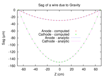
The calculation procedure has been validated by calculating wire sag due to gravitational force and comparing with the analytic solution for gravitational force only as
| (4) |
where and , , are the length, radius and density of the wire respectively. The results has been illustrtaed in fig.1 which has demonstrated the validity of the method.
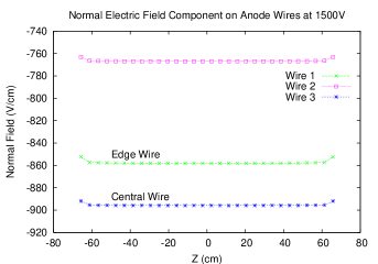
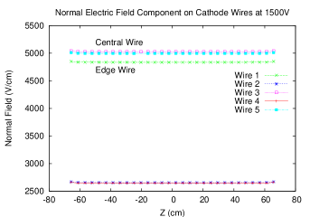
The normal electric field components acting on the anode and cathode wire segments for anode voltage of V have been plotted in fig.2. The field component on each segment has been calculated from the vectorial addition of field components at four radial locations on the segment periphery.
The wire sag at the centre due to electrostatic force following the solution of tridiagonal matrix equation [Eqn.3] has been shown as a function of anode voltage in fig.3 for anode and cathode wires separately. It is evident from the result that the sag in the anode wire changes more rapidly than the cathode wires.
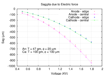
The central wire in the anode plane has been found to undergo more deflection in comparison to the edge wires. The calculation of [3] for wire sags in this chamber has reported less deflection in comparison to our result. In [3], an additional restoring electrostatic force has been considered to be operational when the wire gets deflected which in turn has helped to reduce the wire sag. In our calculation, no such dynamic consideration of the electrostatic force with the wire deflection has been incorporated. To reproduce the actual wire sags, an iterative process can be carried out each time calculating the electrostatic force due to new position of the deflected wire.
5 Conclusion
Using the neBEM solver, the electrostatic field could be accurately calculated for the three dimensional geometry of multiwire RICH chamber. An FDM approach to compute the wire sag has been developed and validated for the case of gravitational sag calculation. In the present calculation, no restoring effect of electrostatic force has been considered unlike the earlier work which has led to larger sag estimates. The restoring force aspect will be implemented in future by iterative technique to estimate a realistic wire sag in this chamber.
References
- [1] ALICE Technical Proposal, CERN-LHCC/95-71, LHCC/P3
- [2] N.Majumdar, S.Mukhopadhyay, Nucl. Instr. Meth. Phys. Research, A 566, p.489 (2006)
- [3] P. Majewski, M.Sc Thesis, Uniwersytet Warszawski, 1996
- [4] J. Va’vra, SLAC-PUB-7627, August 1997
- [5] http://garfield.web.cern.ch/garfield