Onset of unsteady horizontal convection in rectangle tank at
Abstract
The horizontal convection within a rectangle tank is numerically simulated. The flow is found to be unsteady at high Rayleigh numbers. There is a Hopf bifurcation of from steady solutions to periodic solutions, and the critical Rayleigh number is obtained as for the middle plume forcing at , which is much larger than the formerly obtained value. Besides, the unstable perturbations are always generated from the central jet, which implies that the onset of instability is due to velocity shear (shear instability) other than thermally dynamics (thermal instability). Finally, Paparella and Young’s first hypotheses about the destabilization of the flow is numerically proved, i.e. the middle plume forcing can lead to a destabilization of the flow.
pacs:
47.20.Bp, 44.25.+f, 92.10.afHorizontal convection, in which the water is unevenly heated at the horizontal surface, was taken as a model of abyssal ocean circulation. As the abyssal ocean circulation plays an important role in climate change, the horizontal convection has intensively been explored in recent years Paparella and Young (2002); Mullarney et al. (2004); Wang and Huang (2005). It can be set to motion by any small temperature gradient, unlike the Rayleigh-Bénard convection. But similar to Rayleigh-Bénard convection, the horizontal convection may be unsteady at high Rayleigh numbers . There is a critical Rayleigh number , and the steady flow is unstable and becomes unsteady when . The unsteady flow in horizontal convection was first found by numerical simulation Paparella and Young (2002), then was observed in the experiment at Mullarney et al. (2004). This unsteady flow is proved to be non-turbulent even as , though the flow field seems to be chaotic Paparella and Young (2002). The investigation on the unsteady horizontal convection flow is relatively less, except for Paparella and Young (2002); Mullarney et al. (2004); Hughes et al. (2007). However, they have mainly focused on how the turbulent plume maintains a stable stratified circulation. Yet how the horizontal convection turned to be unsteady remains an elusive problem.
To understand this problem, both for the onset of unsteady flow and instability mechanism are of vital. Paparella and Young Paparella and Young (2002) found at in their simulations, which is significantly smaller than others’ results Rossby (1965); Mullarney et al. (2004); Wang and Huang (2005); Hughes et al. (2007); Rossby (1998); Siggers et al. (2004); Sun et al. (2006). For example, Rossby (1965), Wang and Huang (2005) found the flow is steady and stable for in their experiments Rossby (1965); Wang and Huang (2005). Yet other numerical simulations Rossby (1998); Siggers et al. (2004); Sun et al. (2006) have not found unsteady flows for . Paparella and Young Paparella and Young (2002) explained the difference of their results from others’ as: (i) middle plume forcing in the numerical simulations instead of sidewall plume forcing in the experiments, and (ii) lower aspect ratio () in their simulations. Both may lead to destabilization of the flow at lower Rayleigh numbers. However, their hypotheses have not been intensely investigated. According to a recent investigation, the flow is still stable for even at a much lower aspect ratio () Sun et al. (2007). Thus, it maybe the middle plume forcing that leads to destabilization at lower Rayleigh numbers.
Our interest here is to verify their first hypotheses. Is the flow with middle plume forcing less stable than the sidewall plume forcing? How does the instability occur? To investigate these problems, more accurate numerical prediction of is need for both forcing cases, for the spatial resolution of simulation was very lower in the past (e.g. coarse meshes are used in Paparella and Young (2002)). Then the flow field under both middle and sidewall plume forcings are compared, which leads to an affirmative answer of the above problem.
Similar to the previous investigations, we consider the horizontal convection flows within the two-dimensional domain, and the Boussinesq approximation is assumed to be valid for these flows. As shown in Fig.1, the horizontal (y) and vertical (z) regimes are and , respectively. Similar to Rossby (1965), the depth is taken as reference length scale and denotes the aspect ratio. Taking account of divergence-free of velocity field in Boussinesq approximation, the Lagrangian streamfunction and the corresponding vorticity are introduced. The velocity , where horizontal velocity and vertical velocity , respectively. The governing equations in vorticity-streamfunction formulation are Quon and Ghil (1992); Paparella and Young (2002); Siggers et al. (2004):
| (1) |
where denotes the nonlinear advection term. There are two important dimensionless parameter in Eq.(1), i.e. Rayleigh number and Prandtl number , where , , , , and are gravity acceleration, thermal expansion coefficient, surface temperature difference, length of horizontal domain, thermal diffusivity and kinematic viscosity, respectively. Alternatively, Paparella and Youngs used vertical length as length scale, so , where is the vertical Rayleigh number by using vertical length as unit Paparella and Young (2002).
More specifically, we consider the horizontal convection in a rectangle tank at . The tank has same velocity boundary condition as that in Paparella and Young (2002), i.e. free slip and no shear stress at the walls. In addition, two different surface forcings are used, which are central symmetric. One is middle plume forcing as Paparella and Young (2002), the other is sidewall plume forcing as Quon and Ghil (1992); Sun et al. (2007). Comparing these with one cell forcing Rossby (1998), there are two symmetric cells in the flow field under such forcings (e.g. Fig.1 and Fig.6), when the flow is symmetrically steady and stable. In addition, the middle plume forcing in the left cell is the same with the sidewall plume forcing in the right cell (see Fig.1 behind). Thus in the steady flows, both forcings will lead to the same flow patterns except for a position shift, which is proved by the following investigation.
There are two important quantity describing the circulation, i.e. the non-dimensional streamfunction maximum and the non-dimensional heat flux. The non-dimensional streamfunction maximum , where is the maximum of the dimensional streamfunction.
| author | ||||
|---|---|---|---|---|
| Le Quéré (1991) | ||||
| Tian and Ge (2003) | ||||
| Present | ||||
| Le Quéré (1991) | ||||
| Tian and Ge (2003) | ||||
| Present |
The above Eq.(1) is solved with finite different method in non-uniform grids. Crank-Nicholson scheme and Arakawa scheme (e.g. Arakawa, 1966; Orlandi, 2000) are applied to discretize the linear and nonlinear terms, respectively. Comparing to the other schemes, Arakawa scheme is more accurate but more expensive, and it has also been applied to horizontal convection flows at high Rayleigh number Sun et al. (2006, 2007). Table 1 shows the validation of the scheme with nature convection problem. A fine spatial resolution mesh of is used to eliminate numerical instability.
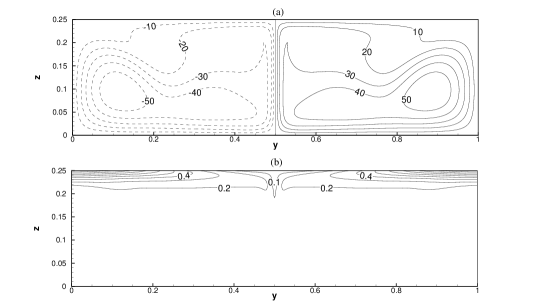
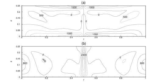
First, the middle plume forcing is considered, which is steady and stable for . Fig.1 shows the flow field (a) and temperature field (b) of with , in which the flow is symmetric, steady and stable. In this case, the center line symmetrically separates the flow field into two parts, like a free slip wall. There is a vigorous downward jet in the center of tank corresponding to the middle plume forcing (Fig.1a), where the vertical velocity field has a minimum of (Fig.2b). The center jet leads to the clockwise and anticlockwise plume cells in the left and right part of tank, respectively. In the left circulation cell, the flow sinks quickly along the center line and upwells clockwise along the left side wall with relatively slower speed, which can be also seen from the vertical velocity of the flow (Fig.2). Besides, there are two horizontal jets respectively near top and bottom walls in the left circulation cell (Fig.2a). Totally, there are 2 horizontal jets near wall and a vertical jet at the center in each cell. Contract to the flow field, the temperature field is very simple. An obvious boundary layer exists near the surface in temperature field, which leads to a 1/5-power law of for heat flux (e.g. Rossby, 1965; Quon and Ghil, 1992; Siggers et al., 2004). And below the temperature boundary layer, the temperature is almost homogeneous due to the convection. Thus there is a very strong stratification near the surface () but a very weak stratification in other region (). As the above case is stable, so the critical Rayleigh number must be larger than , which is significantly larger than the value obtained before Paparella and Young (2002).
To find the critical Rayleigh number , the growth rate of perturbation is calculated numerically. And is assumed to satisfy , where is the complex growth rate of disturbance. It is found that the onset of unsteady flow is at , as shown in Fig.3. For , the flow is stable and the growth rate is approximately . But the flow is unstable and the growth rate is approximately for . Thus the critical Rayleigh number is obtained . The accurate value of is obtained by interpolating from the above result. Moreover, the onset of unsteady flow is found to occur via Hopf bifurcation. As Fig.3 shows, the image part of growth rate is nonzero and the eigenmode of perturbation is periodic. This Hopf bifurcation of the horizontal convection has not been reported yet, and previous investigations dealt only with chaotic flows.

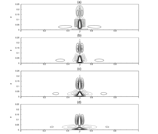
Meanwhile, the evolution of the perturbation vorticity fields during the first half period at (a), (b), (c) and of are depicted in Fig.4, respectively. The perturbation vorticity fields are symmetric about centerline, which implies that the horizontal velocity is nonzero at centerline. It can be seen that the perturbation tripole A (the shadowed ellipse in Fig.4a) is generated from central downward jet, then propagates and amplifies along the central jet downward to the bottom wall (Fig.4b,c,d). When tripole A approaching to the bottom, it becomes weaker and weaker and breaks into two parts: the left and the right near the bottom, which can be seen from the evolution of tripole B (the shadowed rectangle in Fig.4a). And the mean flow advects the broken vortexs horizontally along the bottom wall (Fig.4b,c,d). Then in the second half period, a reverse tripole will generate the same place of vortexes A at , and the same story repeats for it, which is omitted here. In short, the perturbations generate and amplify in the central vertical jet, but are propagated and weakened along the horizontal wall.

Further investigation shows that the instability of flow occurs due to shear. First, as we noting, the instabilities always occur in the center and propagate along the mean flow. Second, this trigger place locates in the area where there is a vigorous jet with strong shear (see e.g. Fig.2b and Fig.5) (Fig.5). As the stratification is very weak here (see e.g. Fig.1b), the flow in this region is dominated by momentum dynamics other than thermal dynamics. All these imply that the onset of instability leading to unsteady flow is due to shear instability at larger Rayleigh numbers, which is much different from Rayleigh-Bénard instability. However, shear is not the sufficient condition for instability. For example, the instability near the top surface is suppressed due to strong stratification (Fig.1b), though both the velocity (Fig.2a) and the shear (Fig.5) near top surface are still very large. In words, the onset of instability is due to velocity shear (shear instability) other than thermally dynamics (thermal instability).
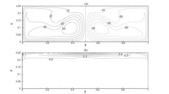
Now, the sidewall plume forcing is considered. Fig.6 shows the flow field and temperature field of , in which the flow is symmetric, steady and stable like that under middle plume forcing. There are two vigorous downward jets near the walls corresponding to the sidewall plume forcing (Fig.6a). As mentioned above, the sidewall plume forcing will lead to exactly the same flow pattern as the middle plume forcing does except for a position shift, which can be seen from Fig.1 and Fig.6. As the flow is stable, the center line like a free slip wall symmetrically separates the two cells. The left cell in Fig.1 is exactly the same with the right cell in Fig.6. However, the flow is much more stable with the sidewall plume forcing. And the critical Rayleigh number is found (with meshes) in this case. As mentioned above, the flow is much more stable with the sidewall plume forcing than that with the middle plume forcing, though both forcings lead to the same flow patterns. This is very interesting, and can be understood from the mechanism of instability.
It’s found that the rigid wall suppresses the perturbation, which leads a more stable flow with the sidewall plume forcing than that with the middle plume forcing. As the loss of stability is due to strong velocity shear in the center in horizontal convection, the smaller the shear is, the more stable the flow is. In the case of middle plume forcing, the perturbation with nonzero horizontal velocity occurs at the most vigorous downward jet. And the perturbed flows cross the center line and propagate downstream. However, in the case of sidewall plume forcing, these crossing flows are suppressed by rigid walls. So that the critical Rayleigh number is much larger in this case. Paparella and Young (2002) hypothesized that middle plume forcing may lead to a destabilization of the flow. Here this hypotheses is proved both physically and numerically.
In conclusion, the onset of unsteady flow is found to occur via a Hopf bifurcation in the regime of for the middle plume forcing at , which is much larger than the previously obtained value. Besides, the onset of unsteady flow is due to shear instability of central downward jet. Finally, the first hypotheses of Paparella and Young (2002) for instability is numerically approved, i.e. the middle plume forcing can lead to a destabilization of the flow at relatively lower Rayleigh numbers.
This work is supported by the National Basic Research Program of China (No. 2007CB816004), the National Foundation of Natural Science (No. 40705027, No. 10602056 and No. 10772172), the National Science Foundation for Post-doctoral Scientists of China (No. 20070410213), and the Presidential Foundation of the Chinese Academy of Sciences, China.
References
- Paparella and Young (2002) F. Paparella and W. R. Young, J. Fluid Mech. 466, 205 (2002).
- Mullarney et al. (2004) J. C. Mullarney, R. W. Griffiths, and G. O. Hughes, J. Fluid Mech. 516, 181 (2004).
- Wang and Huang (2005) W. Wang and R. X. Huang, J. Fluid Mech. 540, 49 (2005).
- Hughes et al. (2007) G. O. Hughes, R. W. Griffiths, J. C. Mullarney, and W. H. Peterson, J. Fluid Mech. 581, 251 (2007).
- Rossby (1965) H. T. Rossby, Deep-Sea Research 12, 9 (1965).
- Rossby (1998) H. T. Rossby, Tellus 50A, 242 (1998).
- Siggers et al. (2004) J. H. Siggers, R. R. Kerswell, and N. J. Balmforth, J. Fluid Mech. 517, 55 (2004).
- Sun et al. (2006) L. Sun, Y. F. Sun, D. J. Sun, and X. Y. Yin, Journal of Hydrodynamics A 21, 252 (2006).
- Sun et al. (2007) L. Sun, Y. F. Sun, D. J. Ma, and D. J. Sun, Acta Physica Sinica 56, 6503 (2007).
- Quon and Ghil (1992) C. Quon and M. Ghil, J. Fluid Mech. 245, 449 (1992).
- Le Quéré (1991) P. Le Quéré, Computers and Fluids 20, 29 (1991).
- Tian and Ge (2003) Z. Tian and Y. Ge, Int. J. Numer. Meth. Fluids 41, 495 (2003).
- Arakawa (1966) A. Arakawa, J. Comput. Phys. 1, 119 (1966).
- Orlandi (2000) P. Orlandi, Fluid flow phenomena (Kluwer Academic publishers, Dordrecht, The Netherlands, 2000).