Formation of long-lived, scarlike modes near avoided resonance crossings in optical microcavities
Abstract
We study the formation of long-lived states near avoided resonance crossings in open systems. For three different optical microcavities (rectangle, ellipse, and semi-stadium) we provide numerical evidence that these states are localized along periodic rays, resembling scarred states in closed systems. Our results shed light on the morphology of long-lived states in open mesoscopic systems.
pacs:
42.25.-p, 05.45.Mt, 73.23.-b, 32.80.RmUnderstanding the properties of long-lived, quasi-bound states in open mesoscopic systems is of central importance for many research subjects, e.g. semiconductor ballistic quantum dots AFB96; AFB97; ZB97; FAB04, photoionization of Rydberg atoms JSSS89, microwave systems HHH99; Stoeckmann00, quantum chaos BMHK02, and optical microcavities ND97; GCNNSFSC98; LLCMKA02; RTSCS02; HCLL02; LRRKCK04; FYC05. In several of these studies the long-lived states are scarred. The original scarring phenomenon has been discovered for closed systems in the field of quantum chaos Heller84. It refers to the existence of a small fraction of eigenstates with strong localization along unstable periodic orbits of the underlying classical system. In open systems, however, scarred states seem to be the rule rather than the exception. The nature of the mechanism behind this scarlike phenomenon is not yet understood.
Avoided level crossings in closed or conservative systems are discussed in textbooks on quantum mechanics. They occur when the curves of two energy eigenvalues, as function of a real parameter , come near to crossing but then repel each other NW29. This behaviour can be understood in terms of a Hamiltonian matrix
| (1) |
For a closed system this matrix is Hermitian, thus the energies are real and the complex off-diagonal elements are related by . The eigenvalues of the coupled system,
| (2) |
differ from the energies of the uncoupled system only in a narrow parameter region where the detuning from resonance, , is smaller or of the size of the coupling strength . The parameter dependence of and can often be safely ignored.
The matrix (1) also captures features of avoided resonance crossings (ARCs) in open or dissipative systems if one allows for complex-valued energies . The imaginary part determines the lifetime of the quasi-bound state far away from the avoided crossing , where the off-diagonal coupling can be neglected. Keeping the restriction allows for two different kinds of ARCs Heiss00. For , there is an avoided crossing in the real part of the energy and a crossing in the imaginary part. At resonance the eigenvectors of the matrix (1) are symmetric and antisymmetric superpositions of the eigenvectors of the uncoupled system. If one of the latter corresponds to a localized state then such an ARC leads to delocalization and lifetime shortening TR99. For , there is a crossing in the real part and an avoided crossing in the imaginary part. This kind of ARC has been exploited to design optical microcavities with unidirectional light emission from long-lived states WH06.
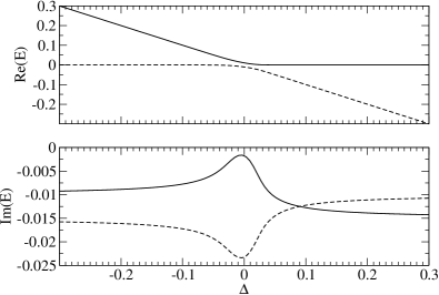
The case is called internal coupling since the only difference to the Hermitian coupling of two states in a closed system is that each state is individually coupled to the continuum. The latter is described by the imaginary part of the diagonal elements of matrix (1). The fully nonhermitian case is more general; it permits an external coupling of the states via the continuum. Figure 1 illustrates that the real part undergoes an avoided level crossing as in the case of a closed system. The important feature is that one of the states has a considerably increased lifetime. The constraint of the conservation of the trace of the matrix in Eq. (1) simultaneously generates a state with short lifetime. The formation of fast and slowly decaying states is known as resonance trapping, see, e.g., Refs. DJ95; PRSB00.
The aim of this letter is to show that ARCs due to external coupling can have a strong impact on the localization properties of long-lived states in open systems. The symmetric or antisymmetric superpositions are more localized in real or phase space than the original states, so that important decay channels are blocked. A surprising finding is that these states can resemble scarred states which helps to explain the frequently observed scarring in open mesoscopic systems.
We examine optical microcavities, where the optical modes and their frequencies play the role of states and their energies. Light confinement in microcavities has attracted considerable interest in recent years due to the huge potential for various research fields and applications, for a review see Ref. Vahala03. For most applications, like low-threshold lasing, long-lived modes are required. We consider quasi-two-dimensional dielectric cavities with rectangular, elliptical and stadium-shaped cross section. We first focus on rectangles because of the following convenient properties: (i) the modes not close to an ARC can be computed analytically to a good approximation, including mode pattern and complex frequency; (ii) the internal ray dynamics is trivial, so localization effects related to chaotic ray dynamics LRKRK05 can be ruled out. Rectangular and square microcavities have already been studied both experimentally and theoretically PCC01; Lohmeyer02; GHLY03. However, ARCs in these systems have not been addressed so far.
We fix one side length to m and vary the aspect ratio . We choose the effective index of refraction to be inside and outside the dielectric for the transverse electric (TE) polarization with magnetic field perpendicular to the cavity plane. Maxwell’s equations for the modes reduce to a two-dimensional scalar wave equation Jackson83
| (3) |
with frequency and the speed of light in vacuum . The wave function and its normal derivative times are continuous across the boundary of the cavity. At infinity, outgoing wave conditions are imposed. Even though the geometry of the cavity is rather simple the wave equation cannot be solved analytically since the boundary conditions introduce diffraction at corners. We compute the modes numerically using the boundary element method Wiersig02b. In order to apply this method each corner is replaced by a quarter of a circle with radius much smaller than the wavelength. We have carefully checked that the rounding does not influence the solutions in the studied frequency regime.
Before we discuss the numerical solutions of the open cavity we will briefly consider the corresponding closed cavity with vanishing wave intensity along the boundary. We expect that the solutions of the closed system approximate those modes in the open system which are confined by total internal reflection. The closed cavity is called an integrable billiard Stoeckmann00 since the modes can be computed analytically
| (4) |
if and ; otherwise . The positive integers , count the number of maxima of in - and -direction, respectively. The normalized frequency belonging to such a mode is given by
| (5) |
As expected for an integrable billiard Stoeckmann00, this system shows frequency crossings instead of avoided crossings when the aspect ratio is varied. For example, for the modes and Eq. (5) yields the crossing point and corresponding to a free-space wavelength of about 960nm. Figure 2 shows that this accidental degeneracy is lifted in the open cavity. The associated ARC equals the case of the matrix in Fig. 1. We therefore conclude that diffraction at corners in rectangular cavities leads to an external coupling of modes.
It has been demonstrated in Ref. Wiersig03 that losses from a polygonal cavity due to diffraction at corners can be estimated by the boundary wave approach. Boundary waves travel along a flat interface between dielectric material and air. In the case of an infinitely extended interface, these waves are evanescent. In the case of a finite interface, however, these waves can leave the interface region at the corners. Following Ref. Wiersig03 we have derived a formula describing the losses from a given mode in the rectangular cavity due to boundary waves
| (6) |
with , , and . For a mode A with and we find corresponding to a quality factor of . For a mode B with and we get and . The boundary wave approach as developed in Ref. Wiersig03 can only compute the losses of individual modes, i.e. the diagonal elements of the matrix (1). The off-diagonal part, i.e. the coupling of modes, cannot be determined within this approach. For a direct comparison to the exact results in Fig. 2 it is therefore useful to consider the mean value of and since here the ARC contributions cancel; cf. Eq. (2). The result of this procedure is shown in the bottom panel of Fig. 3. It can be seen that the averaged boundary wave result overestimates the averaged lifetimes of the modes by just 20 percent. Hence, leakage due to boundary waves is the dominant decay channel.
At the center of the ARC, , in Fig. 2 a fast mode D with and a slow mode C with is formed. The slow mode has which is a dramatic increase by more than one order of magnitude if compared to the “normal” quality factor. In this frequency regime the leakage due boundary waves limits the quality factor to roughly . This indicates that possibly all long-lived modes (modes with, say, ) in this frequency regime are caused by ARCs. This conclusion is supported by extensive numerical studies on this system (not shown).


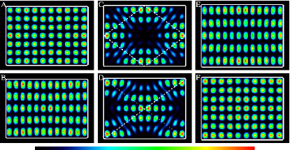
The spatial patterns of modes A, B, E, and F in Fig. 4 approximately match the solutions of the closed cavity in Eq. (4). Upon the avoided crossing the mode patterns exchange their character, i.e. mode B and E have roughly the same spatial profile but belong to different frequency branches; cf. Fig. 2. The same holds for mode A and F. The modes at the ARC, C and D, correspond to symmetric and antisymmetric superpositions of the mode A and B (or E and F). Now, we can identify the physical mechanism behind the increased quality factor of mode C: destructive interference reduces the light intensity at the corners and consequently the main decay channel, leakage due to boundary waves, is strongly suppressed. A closer inspection of the mode C in Fig. 4 reveals that its intensity is concentrated along a diamond-shaped periodic ray. The long-lived mode formed in the ARC therefore resembles a scarred mode. In the case of mode D, constructive interference at the corners spoils the quality factor. Mode D is localized along two symmetry-related rays connecting the corners of the cavity. Such kind of rays are called diffractive rays HHH99.
The spatial pattern of mode C is not a special feature of the chosen boundary conditions but is also observed in square cavities of very different types: (i) square quantum dots with leads attached at the corner region AFB96; (ii) square billiards with magnetic flux NPZ00; (iii) vertical-cavity surface-emitting lasers with square-shaped cross section HCLL02; CHLL03.
The resemblance of mode C with the diamond-shaped periodic ray is apparent with the naked eye. In the following, it will be demonstrated that the relation is even deeper. To do so, we estimate the frequency of the mode by using the localization along the ray. We stipulate that an integer number of wavelengths fits onto the periodic ray with length . The calculation is straightforward giving
| (7) |
with being the total phase shift from the reflection at the dielectric boundary for TE polarization. The quantities and are the same as for Eq. (6) but with , and . The top panel of Fig. 3 demonstrates that the scar approximation with describes the mean behaviour of the modes involved in the ARC over a broad range of parameter values. The small frequency offset of about can be traced back to the fact that the scar approximation assumes that the plane waves lying on the ray segments have no wave vector component in the transverse direction. However, the mode is restricted to an interval of length () in -direction (-direction). At least half a wavelength fits into these intervals for which the wave vector components give frequency contributions of approximately and . Summing up the squares of the frequency contributions gives the correction . In the regime we get which convincingly explains the discrepancy between and the exact value of .
Coupling between two modes ) and occurs only for modes with the same symmetry with respect to the lines and . That implies that if is even (odd) must be even (odd) too. The same holds for and . Interestingly, this restriction ensures that for given allowed pair ) and cancellation at all corners is possible.
We can create a variety of scarlike modes near ARCs. Consider a periodic ray bouncing times at the horizontal lines and times at the vertical lines. A straightforward analysis shows that and where denotes the integer part. Figure 5(a) depicts an example with and . This long-lived mode with () results from an ARC of modes and at .
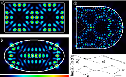
The formation of long-lived, scarlike modes near ARCs with external coupling is not restricted to TE polarization nor to the rectangular geometry. Figures 5(b)-(e) show examples with transverse magnetic (TM) polarization in an elliptical and a (semi-) stadium-shaped resonator with refractive index . The shape parameter is the eccentricity and the length of the horizontal straight lines , respectively. The scenario is as in the cases shown in Figs. 1 and 2. At the ARC a short- and a long-lived mode is formed; see Fig. 5(c) and (e). The long-lived mode exhibits a localization along a periodic ray; see Fig. 5(b) and (d). This localization gradually disappears when the shape parameter is detuned from resonance (not shown). Note that elliptical billiards do not show such scarring WWD97. Let us mention that local maxima of quality factors as function of a shape parameter had already been exploited for minimizing losses from stadium-shaped cavities FYC05. However, the case in Ref. FYC05 is not related to ARCs, but is an interference effect of unstable periodic rays FHW06.
In summary, we demonstrated the formation of long-lived modes near avoided resonances crossings in optical microcavities. For a number of different types of cavities (rectangular, elliptical, and stadium-shaped) we observed strong localization of these modes, resembling scarred states. We expect that this finding is highly relevant for understanding the localization properties of long-lived states not only in optical systems but in various fields of research.
We acknowledge helpful discussions with M. Hentschel, F. Anders T. Y. Kwon, and T. Gorin.