Electron interferometry with nano-gratings
Abstract
We present an electron interferometer based on near-field diffraction from two nanostructure gratings. Lau fringes are observed with an imaging detector, and revivals in the fringe visibility occur as the separation between gratings is increased from 0 to 3 mm. This verifies that electron beams diffracted by nanostructures remain coherent after propagating farther than the Talbot length mm, and hence is a proof of principle for the function of a Talbot-Lau interferometer for electrons. Distorted fringes due to a phase object demonstrates an application for this new type of electron interferometer.
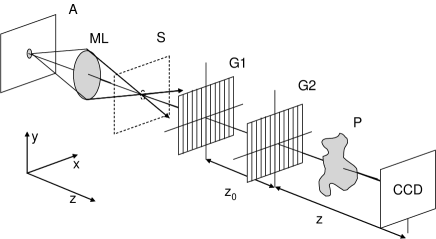
Near-field interference effects that result in self-similar images of a periodic structure were noticed by Talbot in 1836, and later described as Fourier images Talbot (1836); Cowley and Moodie (1957a); Patorski (1989). One remarkable feature is that revivals in image visibility occur periodically as the plane of observation is separated from the periodic structure. The visibility of self-images is maximized at half-integer multiples of the Talbot distance , with being the period of the structure and the wavelength of the light or de Broglie waves illuminating the structure. Partially coherent waves are required to observe self-images of a single grating (the Talbot effect). However, a related phenomenon (the Lau effect) occurs with incoherent light if two gratings are used Patorski (1989); Lau (1948); Jahns and Lohmann (1979). Fringes are then formed behind the second grating, and the fringe visibility oscillates as a function of grating separation. These Lau fringes have maximum visibility on a distant screen when the gratings are separated by , with being an integer. In a Talbot-Lau interferometer, Lau fringes are detected with the aid of a third grating, but the fringes can also be observed directly on a screen, thus making a Lau interferometer as shown in Figure 1.
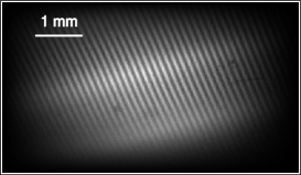
Here we present a Lau interferometer for electrons based on two nanostructure gratings that each have a period of nm. With medium energy (5 keV) electrons that have a de Broglie wavelength of = 17 pm, the Talbot length is 1.16 mm. An imaging detector 80 cm beyond the gratings was used to observe the Lau fringes shown in Figure 2, and the fringe visibility as a function of grating separation is plotted in Figure 3. If the fringes are analyzed with a third grating (even a digital grating in the image processing can achieve this purpose), then this apparatus serves as a Talbot-Lau interferometer. However, even more information is gained by studying images of the Lau fringes directly.
Interferometers based on the Talbot and Lau effects have found applications in light optics Patorski (1989); Jahns and Lohmann (1979); Silva (1972), in atom optics Chapman et al. (1995); Nowak et al. (1997); Clauser and Li (1994); Brezger et al. (2002, 2003), and more recently with x-rays David et al. (2002). Yet even though electron interferometry is a mature field Tonomura (1987); Tonomura et al. (1995); Tonomura (1999), neither Lau nor Talbot-Lau interferometer designs have been operated with electrons until now.
Perhaps the chief reason that Talbot-Lau interferometers have not previously been created for electrons is that suitable periodic structures have not been available. Crystals with a lattice period on the order of 1 nm can serve as a grating, but the resulting Talbot length of 200 nm is too short for many practical interferometer experiments not . A further complication is that the angular misalignment of the two gratings must be smaller than one grating period over the height of the beam. Hence alignment within radians is required when using crystal gratings and a 1 mm high beam. These limitations are overcome by using nanostructure gratings with a 100 nm period. Then the talbot length is increased to 1 mm, and the alignment tolerance is relaxed to radians.
Nanostructures for electron optics are new. The gratings that we use are fabricated at MIT Savas et al. (1995), and were only recently used to study electron diffraction Gronniger et al. (2005); McMorran et al. (2006). Similar gratings have enabled several atom interferometers Keith et al. (1991); Carnal and Mlynek (1991); Clauser and Li (1994); Brezger et al. (2002), and thicker gratings have given first light to x-ray Talbot interferometers David et al. (2002). That nano-structures can be used for coherent electron optics was not obvious for several reasons. Local charging of the nano-structures, non-uniform image charge interactions with the nano-structures, and the possibility of coulomb drag and electron energy loss due to passing within a few nanometers of a surface are just a few mechanisms that could lead to decoherence. Our results show that sufficient coherence is maintained to operate an electron interferometer with nanostructure gratings.
In the rest of this paper we describe the electron optics setup, and the diffraction theory used to study the revivals in Figure 3. We comment on the role of image charge interactions between electrons and the nano-gratings. Then we demonstrate an application of this interferometer: the study of the index of refraction for electrons due fields around a charged needle tip.
The Lau fringes have highest visibility when the grating separation () and the distance to the screen () satisfy
| (1) |
Then the period of the Lau fringes is
| (2) |
where is the period of the gratings. Equations 1 and 2 are derived in the Fresnel approximation in references Silva (1972); Patorski (1989); Brezger et al. (2003). Because the distance to the screen is typically 800 times as long as the separation between gratings () in our experiment, the fringes are effectively magnified so that . The ratio of periods for G1, G2 and the detected fringes is therefore 1:1:800.
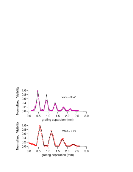
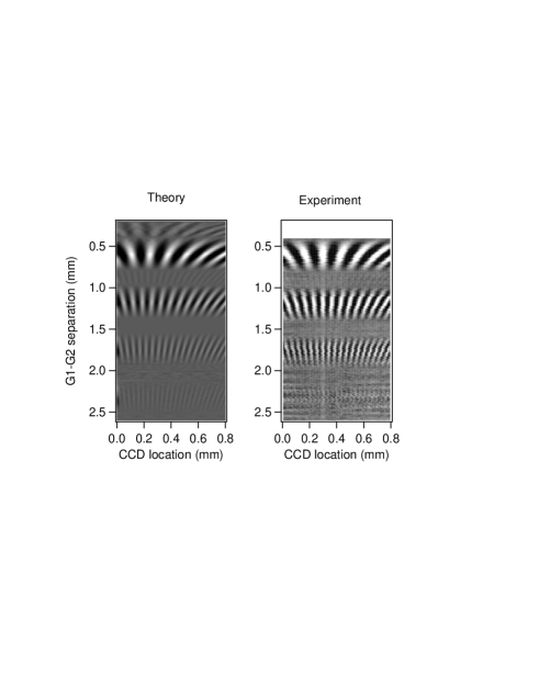
To describe in detail the shape and visibility, , of the fringes as a function of grating separation we relied on a calculation given in Equation 3 of reference Brezger et al. (2003). Briefly, the concept is that the first grating is considered to be a set of mutually incoherent point sources of monochromatic waves. Waves from each point source are diffracted by G2 and arrive at the imaging screen in the near-field (Fresnel) diffraction regime. The intensity pattern on the screen is generated by adding diffraction patterns from each point source. Grating G1 and the screen define the position of many sources and detectors; they function as classical components. In contrast, grating G2 acts as a quantum mechanical diffraction object. This theory was used to generate the curves in Figure 3 and the theoretical portion of Figure 4.
We are justified in considering incoherent illumination of G1 by the van Cittert-Zernike theorem, which gives the transverse coherence length, in terms of , the angle subtended by the source. The electron beam is focused to a 10 m spot just 2 cm in front of G1 (see figure 1) and the spot size in this plane cannot be made smaller because of the extended electron source and lens abberations. This corresponds to a coherence length of nm, which is smaller than the grating period of nm.
As remarked in reference Brezger et al. (2003), the essential coherent effect is diffraction at the second grating. The first grating simply serves as an array of sources, and the fringes could be detected by a transmission mask (with a period ) and an integrating detector. One virtue of using an imaging detector, with a digital sampling density of 100 pixels per mm, is that we can study fringes of varying period () as the grating separation () is changed. Images also reveal the fractional Talbot effect by showing fringes of half the period compared to that given by Equation 2, when the grating separation is three quarters of the Talbot length, . The fractional Talbot effect was also observed with .
Our experimental data are best fit by a grating transmission function for G1 and G2 that is described by a 35% open fraction, and a weak image-charge interaction between electrons and the grating bars. Image-charge interactions were discussed in detail in Gronniger et al. (2005); McMorran et al. (2006), and the have a similar effect on the electron optics as the Casimir-Polder interaction does for atom optics Brezger et al. (2003); Grisenti et al. (1999); Perreault et al. (2005). We include the strength of the image-charge and the physical size of the grating windows as two free parameters in the transmission function for the second grating. The best fit image charge for 3 keV electrons is , and the best fit image charge for 5 keV electrons is only . This suggests that the electron-surface interaction at the nanometer scale depends on the velocity of electrons with respect to the surface. More research to investigate this is under way.
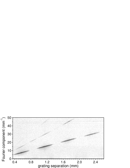
Additional analysis of the shape of the fringes was accomplished by taking the Fourier transform of images such as Figure 2. These image transforms show how the spatial frequency of the fringes change with grating separation. A composite image of fringe spectra, in which each column represents the spatial frequency spectrum of fringes for a specific grating separation , is shown in Figure 5. The fractional Talbot effect is clear at the grating separation mm. The higher harmonics of spatial frequency indicate that the fringes are not purely sinusoidal, but tend in places to look more like the binary (Ronchi rule) masks made by ideal absorbing nanostructure gratings. This is the self-imaging property of the Talbot and Lau effects.
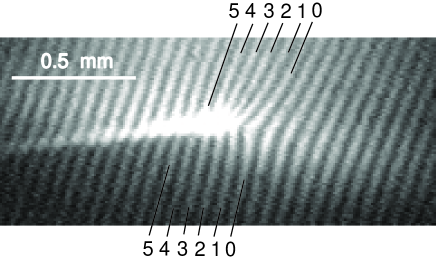
To demonstrate that this interferometer can be used to study phase shifts for electrons due to various objects, we inserted a charged wire in the beam after the second grating in plane P of Figure 1. Like a lightening rod, the tip of the wire causes large gradients in electric potential. The electric potential in the space around the wire changes the index of refraction for electron waves and distorts the interference fringes as shown in Figure 6.
Multiple paths through the interferometer sample different parts of the phase object, therefore we are sensitive only to gradients in phase, not phase directly. This design is known as a shearing interferometer and shifts in fringe position are proportional to and distortion in the fringes is associated with , where , with being the index of refraction Patorski (1989); Silva (1972); Jahns and Lohmann (1979); Tonomura (1987, 1999); Tonomura et al. (1995); David et al. (2002). For electron de Broglie waves this is where is the electric potential, is the incident energy of the electrons, the electron mass, the magnitude of the electron charge, and is Planck’s constant divided by .
Because phase gradients are caused by energy gradients, i.e. forces, the sensitivity demonstrated here is not different in principle from a deflection sensor that can study classical forces on electrons. However, the virtue of the interferometer is still apparent because the fringes make it easier to detect deflections. One advantage is that the fringe period is 10 times finer than the smallest focus that could be produced with the incoherent beam and abberations of the lens system in this apparatus. Second, the fringes are formed simultaneously over a large spatial region without scanning the beam.
A continuous wire produces a uniform linear phase gradient () with opposite sign on either side of the wire. That is how it serves as a bi-prism Tonomura (1999). Around the tip of the freely suspended charged wire, however, there is a strong double gradient term (). Hence fringe distortion is expected around the tip of the charged wire, and uniform fringe shifts are expected along the sides of the charged wire. Since the shifts are perpendicular to the wire, and in general the wire can be skew to the grating bars, fringes on either side of the wire can appear out of step as indicated in figure 6. This serves as a proof of principle that the interferometer setup presented here can be used to study differential phase shifts due to a phase object.
At the time of writing of this manuscript, we are aware of the construction of a Mach-Zehnder electron interferometer in the group of H. Batelaan, which requires a much higher degree of electron spatial coherence than our interferometer. Our results are distinct in that we use an incoherent electron beam and we image electron interference fringes directly. The imaging tool allows us to detect fringes with arbitrary period (), and thus permitted us to study quantitatively the revivals in fringe visibility as a function of grating separation. Imaging also enabled us to observe the fractional Talbot effect with electrons and nanostructures. The most useful result of using an imaging detector is the ability to study fringe distortions due to phase objects in the electron interferometer.
In conclusion, we demonstrated a novel electron interferometer that uses two nanostructure gratings and near-field interference effects. We demonstrated the Lau effect for electrons and observed revivals in fringe visibility when the gratings are separated by multiples of the Talbot length. This type of electron interferometer does not require spatially coherent electron waves from the electron gun, but still it tests how well the nanostructures generate and preserve coherence for electron waves. The effect of image-charge interactions between electrons and the grating structure was observed, but it does not inhibit the electron interference. The apparatus is a rudimentary sheering interferometer, and serves to demonstrate differential phase shifts. We have thus shown that metal-coated silicon nitride nanostructure gratings can be used as elements for coherent electron optics.
The authors acknowledge D. Bentley for the electron gun, and Mark Robertson-Tessi for technical assistance. This work was supported by the National Science Foundation Grant No. 0354947, and No. 0526954.
References
- Talbot (1836) H. F. Talbot, Philos. Mag. 9, 401 (1836).
- Cowley and Moodie (1957a) J. M. Cowley and A. F. Moodie, Proc. Phys. Soc. London 70, 486 (1957a); 70, 497 (1957b); 70, 505 (1957c); 76, 378 (1960).
- Patorski (1989) K. Patorski, Progress in Optics 27, 3 (1989).
- Lau (1948) E. Lau, Ann. Phys. 6, 417 (1948).
- Jahns and Lohmann (1979) J. Jahns and A. W. Lohmann, Opt. Comm. 28, 263 (1979); H. O. Bartelt and J. Jahns, Opt. Comm. 30, 268 (1979).
- Silva (1972) D. E. Silva, Applied Optics 11, 2613 (1972).
- Chapman et al. (1995) M. S. Chapman, C. R. Ekstrom, T. D. Hammond, J. Schmiedmayer, B. E. Tannian, S. Wehinger, and D. E. Pritchard, Phys. Rev. A 51, R14 (1995).
- Nowak et al. (1997) S. Nowak, C. Kurtsiefer, T. Pfau, and C. David, Opt. Lett. 22, 1430 (1997).
- Clauser and Li (1994) J. F. Clauser and S. Li, Phys. Rev. A 49, R2213 (1994).
- Brezger et al. (2002) B. Brezger, L. Hackermuller, S. Uttenthaler, J. Petschinka, M. Arndt, and A. Zeilinger, Phys. Rev. Lett. 88, 479 (2002).
- Brezger et al. (2003) B. Brezger, M. Arndt, and A. Zeilinger, Journal of Optics B 5, S82 (2003).
- David et al. (2002) C. David, et al., App. Phys. Lett. 81, 3287 (2002); A. Momose, et al., Jap. J. App. Phys. 42, L866 (2003); A. Momose, Jap. J. App. Phys. 44, 6355 (2005); T. Weitkamp, et al., App. Phys. Lett. 86 (2005).
- Tonomura (1987) A. Tonomura, Rev. Mod. Phys. 59, 639 (1987).
- Tonomura et al. (1995) A. Tonomura, L. F. Allard, G. Pozzi, D. C. Joy, and Y. A. Ono, eds., Proceedings of the International Workshop on Electron Holography (Elsevier, 1995).
- Tonomura (1999) A. Tonomura, Electron Holography (Springer, 1999).
- (16) For this calculation we assumed high energy (100 keV) electrons with a de Broglie wavelength of = 3.9 pm. Lower energy electrons make the Talbot length even shorter.
- Savas et al. (1995) T. A. Savas, S. N. Shah, M. L. Schattenburg, J. M. Carter, and H. I. Smith, J. Vac. Sci. Technol. B 13, 2732 (1995); T. A. Savas, M. L. Schattenburg, J. M. Carter, and H. I. Smith, J. Vac. Sci. Technol. B 14, 4167 (1996).
- Gronniger et al. (2005) G. Gronniger, B. Barwick, H. Batelaan, T. Savas, D. Pritchard, and A. Cronin, App. Phys. Lett. 87 (2005).
- McMorran et al. (2006) B. McMorran, J. D. Perreault, T. A. Savas, and A. Cronin, Ultramicroscopy 106, 356 (2006).
- Keith et al. (1991) D. W. Keith, C. R. Ekstrom, Q. A. Turchette, and D. E. Pritchard, Phys. Rev. Lett. 66, 2693 (1991).
- Carnal and Mlynek (1991) O. Carnal and J. Mlynek, Phys. Rev. Lett. 66, 2689 (1991).
- Grisenti et al. (1999) R. E. Grisenti, W. Schollkopf, J. P. Toennies, C. C. Hegerfeldt, and T. Kohler, Phys. Rev Lett. 83, 1755 (1999).
- Perreault et al. (2005) J. D. Perreault, A. D. Cronin, and T. A. Savas, Phys. Rev. A 71, 053612 (2005).