Fabrication of alignment structures for a fiber resonator by use of deep-ultraviolet lithography
Abstract
We present a novel method to mount and align an optical-fiber-based
resonator on the flat surface of an atom chip with ultrahigh precision.
The structures for mounting a pair of fibers, which constitute the
fiber resonator, are produced by a spin-coated SU-8 photoresist
technique by use of deep-UV lithography. The design and production
of the SU-8 structures are discussed. From the measured finesses we
calculate the coupling loss of the SU-8 structures acting as a kind
of fiber splice to be smaller than 0.013 dB.
I Introduction
Although integrated optics is a widespread and important field in today’s technology, especially in the telecommunication sector, integrated optics is also beginning to gain in importance in other areas, such as atomic physics and quantum optics. In the developing field of quantum information processing, the manipulation of neutral atoms with so-called atom chips provides a new, extremely promising approach folman ; folman2 . The concept relies on the capability to control magnetically trapped atoms that hover micrometers above a microstructured surface that carries electric currents and charges to provide the necessary fields. As far as we know, integrated optical access to trapped atoms has not yet been implemented on these atom chips.
An important step will be the on-chip detection of single atoms that can be achieved with an optical fiber resonator horak . In our approach, the fibers are mounted in a superstructure fabricated from SU-8 resist that provides positioning and alignment accurately and easily. The fibers can easily be inserted by hand and are automatically aligned with submicrometer precision.
SU-8 is an epoxy-based, chemically amplified solvent-developed negative resist that is typically patterned with 365-436 nm UV aligners. Its specific properties facilitate the production of thick structures with smooth, nearly vertical sidewalls microchem2 . Because of the high mechanical, chemical, and thermal stability of the polymerized SU-8, it has been used to fabricate a wide range of microcomponents, such as optical planar waveguides with outstanding thermal stability and controllable numerical apertures, mechanical parts such as microgears for engineering applications, microfluidic systems, and microreactors for biochemical processing ruhmen4 .
To assess the quality of the alignment structures, we use the fiber resonator itself. Since the finesse of the resonator strongly depends on losses introduced by misalignment, it is a good way to measure the coupling efficiency and alignment precision of the SU-8 fiber splice.
II Fiber resonator setup
The fiber setup is sketched in Fig. 1(a). We use a Fabry-Perot-type resonator that is produced by coupling two pieces of single-mode fiber (4.9 µm mode field diameter) with dielectric mirrors glued to the outer ends of the fibers marco . A small gap of a few micrometers between the inner ends of the fibers provides access to magnetically trapped atoms that interact with the light field. An important property of a resonator is its finesse which can be written as
| (1) |
where is the loss factor per single pass, is the free spectral range, and is the full width at halfmaximum of the resonances. The approximation is valid for . For a more detailed description of resonator theory we refer the reader to the textbooks listed in Refs. demtroeder and siegman . With a resonator of sufficient finesse (), the additional loss caused by light scattering inside the gap by atoms can be used to detect the presence of even single atoms in the gap horak . To obtain a high enough finesse, the fiber ends must be aligned with submicrometer precision.
II.1 Intrinsic losses
In the following, all the loss mechanisms of the intact fiber resonator are referred to as intrinsic losses, i.e., all the losses without introducing the gap. The losses are basically determined by the quality of the glued mirrors at the ends of the fiber. The loss caused by the fiber itself is 3 dB/km as stated by the manufacturer. With a typical length of cm for our resonators, this is equivalent to a negligible loss of 0.0003 dB or 0.007 %. In principle, the transmission through the mirrors is determined by the properties of the dielectric stack and can be chosen to meet specific requirements. But the thickness of the glue layer, the alignment precision, internal losses, and the surface roughness limits the achievable reflectivity. The most important limitation, which cannot be overcome, is the spreading of the unguided light mode in the glue layer and within the mirror itself. This leads to a reduced coupling of the reflected light back into the fiber.
II.2 Losses caused by the gap
After cutting the resonator and introducing the gap, the light coupling between the two pieces will be reduced, thus introducing additional loss, which results from light scattering at the newly introduced surfaces and from transversal, angular, and longitudinal misalignment. The relevant geometric parameters are shown in Fig. 1(b). Rotational misalignment converts a potentially imperfect core-cladding concentricity into transversal misalignment saruwatari .
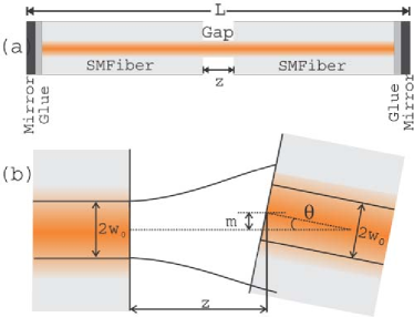
For a fiber with a single-step refractive index profile, a Gaussian approximation ghatak for the fundamental mode field distribution can be used. Typically, the Gaussian approximation deviates by less than 1% from the true mode field. In general, the power coupling efficiency for two fibers can be calculated by the overlap integral of the fiber optical field modes. The efficiency decreases quadratically with the geometric parameters for small deviations from perfect alignment. We found that the crucial parameters for efficient light coupling are the transversal misalignment and the angle between the optical axes of the two fiber pieces. Because of the weak dependence of the mode field diameter in the near field, the coupling loss caused by longitudinal misalignment is not so critical. One must take into account that Fresnel backreflection at the gap surfaces leads to a coupled system of three resonators. But the influence of longitudinal mode symmetry on the resonator finesse vanishes for small gap sizes.
III Deep-Ultraviolet lithography by use of SU-8 photoresist
III.1 Structure requirements
The alignment structures for the fiber resonator must meet some specific requirements. They must be able to tolerate temperature changes and gradients. In typical experiments with atoms trapped in microscopic potentials, the currents carried by the metallic structures lead to a local temperature increase of as much as 100 ℃. Furthermore, the structure must be taller than the fiber radius ( µm) and an exposure in thick resist is needed. To prevent lateral and angular misalignment, i.e., parallel and perpendicular to the substrate plane, an undercut sidewall profile is superior to a vertical sidewall profile. With such a profile, the separation between the sidewalls decreases proportional to the distance from the substrate surface [see Fig. 2(c)], thus clamping the fiber. To meet these requirements, SU-8 is highly suitable, because of its thermal stability and outstanding lithographic performance. The undercut sidewall profile can be obtained by optimization of the lithographic process steps. The optimization techniques include fine-tuning of the exposure dose and the postexposure bake (PEB) time.
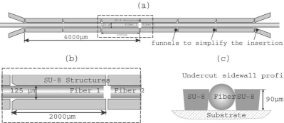
The layout of the desired alignment structure with fibers is shown in Fig. 2. This design includes funnels to simplify the insertion of the fiber. To avoid angular misalignment, the total length of the alignment structure was chosen to be 6000 µm, and it is divided into several subsegments to reduce stress induced by thermal expansion.
III.2 Optimization of the fabrication process
The process for the fabrication of alignment structures includes substrate coating, soft bake, UV exposure, PEB, and development. Each process has a strong influence on the final structure, and there are complex interrelations among the single process steps. Substrate cleaning and dehydrate baking prior to spin coating can improve SU-8 adhesion. An insufficient soft bake results in mask adhesion and an uneven resist layer. On the other hand, a too long soft bake time causes stress and cracking in the final structures. The degree of polymerization is controlled by both the exposure dose and the bake conditions. All these interrelations increase the complexity of optimization. To accelerate the optimization process, we limited the variation of the process to parameters that have the strongest influence on the final results. Specific to our project, the slight undercut sidewall profile is important and can be optimized by varying the exposure dose and the PEB conditions. Compared with the PEB conditions, the exposure dose has a stronger influence on the sidewall profile, therefore the optimization was performed by a variation of the exposure dose.
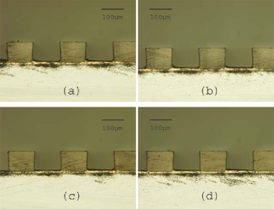
The entire process is described in detail in the following. To improve the adhesion of SU-8 films, the gold-coated silicon substrates were cleaned in an ultrasonic bath for 5 min at room temperature. They were subsequently rinsed in distilled water and then dehydrated on a hot plate at 200 ℃ for 1 h immediately before use. After cooling to room temperature, approximately 3 g of SU-8 50 resist was spread over 5 cm 5 cm of the substrate around the central area. Spin coating the resist at 500 rpm for 20 s, followed by 2000 rpm for 20 s produced an approximately 90 µm thick film. The coated film was then prebaked on a hot plate in two steps to evaporate the solvent. In the first step we used a temperature of 65 ℃ for 10 min. Then the temperature was ramped up to 95 ℃ for approximately 6 min and then held constant at 95 ℃ for 2 h. After cooling to room temperature, the substrate was exposed with the desired pattern mask by use of a standard 365 nm UV light source. To optimize the undercut sidewall profile, we used a reduced exposure dose. During the PEB time, the exposed area of the SU-8 film was selectively polymerized. The postbake process was also performed in two steps. The substrate was placed on the hot plate at 65 ℃ for 1 min. This step is necessary to avoid an image flow before the resist is slightly polymerized. Then the substrate was immediately put on another hot plate at 95 ℃ for 10 min. After the PEB, the substrate was removed from the hot plate and cooled to room temperature. Finally, the nonpolymerized regions of the SU-8 film were removed in SU-8 developer for 12 min. To observe the sidewall profile, the substrate was cut with a precision dicing saw. The microscopic images of the sidewall profiles are shown in Fig. 3 for different exposure times. The pictures indicate that the degree of undercut becomes larger with smaller exposure doses. This result can be explained by light diffraction at the mask aperture. Because the adhesion of the resist to the substrate decreases with lower exposure, we chose a compromise between an acceptable undercut and a sufficient adhesion, which corresponds to that in Fig. 3(b)).
IV Results
We determined the quality of the SU-8 fiber splice indirectly by first measuring the finesse of an intact resonator and then splitting and inserting it into the structures. We recorded the transmitted light intensity while scanning the laser over several free spectral ranges of the fiber resonator. A model function was fitted to the data, yielding the finesse according to Eq. (1). The results were averaged over several hundred runs of the experiment. The finesses of two intact resonators were found to be and . After cutting the resonators and polishing the surfaces, the pieces were introduced into the SU-8 structures. We observed the fiber ends under a microscope and minimized the gap sizes to touching fibers. The finesses were then measured to be and , thus giving an additional average loss of or () dB. Neglecting other additional losses, this corresponds to a pure lateral misalignment of nm or a pure angular misalignment of rad . To test thermal stability, we varied the temperature of the substrate between 20 and 70 ℃. The finesse of the inserted fiber resonator showed no change during heating.
V Conclusion
In summary, we have demonstrated a method for aligning fibers on a flat surface by using SU-8 superstructures. The aligned fibers represent a Fabry-Perot-type resonator for atomic physics to detect atoms. We have investigated the different loss mechanisms for this type of fiber resonator. We then introduced the layout of the SU-8 alignment structures, which enables easy positioning and alignment, and because of the undercut sidewall profile, also offers a method of fixing the fiber position. To achieve this structure, we optimized the lithographic process. Furthermore we demonstrated a technique for quantifying the losses that are due to misalignment with the help of the fiber resonator itself. The finesse measurement indicated that the SU-8 superstructures are of superior quality.
VI Acknowledgements
We thank S. Groth for supplying gold-coated silicon substrates. This research was partly supported by European Union contract IST-2001-38863 (Atom Chip Quantum Processor collaboration) and the Landesstiftung Baden/Württemberg Forschungsprogramm Quanteninformationsverarbeitung.
References
- (1) R. Folman, P. Krüger, J. Schmiedmayer, J. Denschlag and C. Henkel, “Microscopic atom optics: From wires to an atom chip”, Adv. At. Mol. Opt. Phys. 48, 263-356 (2002).
- (2) R. Folman, P. Krüger, D. Cassettari, B. Hessmo, T. Maier and J. Schmiedmayer, “Controlling cold atoms using nano-fabricated surfaces: Atom Chips”, Phys. Rev. Lett. 84, 4749-4752 (2000).
- (3) P. Horak, B.G. Klappauf, A. Haase, R. Folman, J. Schmiedmayer, P. Domokos and E.A. Hinds, “Possibility of single atom detection on a chip”, Phys. Rev. A67, 043806/1-9 (2003).
- (4) Microchem, http://www.microchem.com, NANO SU-8 50; The SU-8 photo-resist for MEMS, http://aveclafaux.freeservers.com/SU-8.html.
- (5) R. Ruhmann, K. Pfeiffer, M. Falenski, F. Reuther, R. Engelke and G. Grützner, “SU-8: a high performance material for MEMS applications”, Polymers in MEMS, http://www.microchem.com/resources/tok_ebeam_resist.pdf.
- (6) M. Wilzbach, Physikalisches Institut der Universität Heidelberg, Philosophenweg 12, D-69120 Heidelberg, Germany, is preparing a manuscript to be called “Building micro-cavities with optical fibers for single atom detection.”
- (7) W. Demtröder, “Laser Spectroscopy”, Springer Verlag, Berlin - Heidelberg (2003).
- (8) A.E. Siegman, “Lasers”, University Science Books, Mill Valley, CA (1986).
- (9) M. Saruwatari and K. Nawate, “Semiconductor laser to single-mode fiber coupler”, Appl. Opt. 18 (11), 1847-1856 (1979).
- (10) A. Ghatak and K. Thyagarajan, “Introduction to fiber optics”, Cambridge University Press (1998).