Present address: ]Department of Physics and Astronomy, University of California, Irvine, CA 92697, U.S.A.
Large-mode-number magnetohydrodynamic instability driven by sheared flows
in a tokamak plasma with reversed central shear
Abstract
The effect of a narrow sub-Alfvénic shear flow layer near the minimum of the tokamak safety factor profile in a configuration with reversed central shear is analyzed. Sufficiently strong velocity shear gives rise to a broad spectrum of fast growing Kelvin-Helmholtz (KH)-like ideal magnetohydrodynamic (MHD) modes with dominant mode numbers . Nonlinear simulations with finite resistivity show magnetic reconnection near ripples caused by KH-like vortices, the formation of turbulent structures, and a flattening of the flow profile. The KH modes are compared to double tearing modes (DTM) which dominate at lower shearing rates. The possible application of these results in tokamaks with internal transport barrier is discussed.
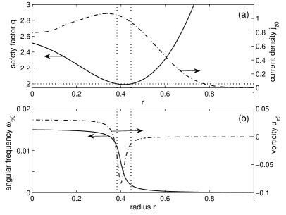
Shear flows can give rise to the well-known Kelvin-Helmholtz instability (KHI) which, in magnetohydrodynamic (MHD) systems, has to compete with field line tension, magnetic pressure and magnetic shear.Chandrasekhar (1961) Regions in the plasma which are particularly susceptible to KHI are therefore those where it can couple with MHD instabilities. A system where such coupling is expected to play an important role, and which motivated the present study, is the reversed-shear (RS) advanced tokamak configuration, which is a strong candidate for achieving self-sustained nuclear fusion conditions. It has a non-monotonic toroidal current profile [Fig.1(a)] and the magnetic shear, , changes its sign at some radius . Here is the radial coordinate (minor radius of the torus), and is the safety factor profile measuring the field line pitch [Fig.1(a)]. In the region with negative shear () pressure-driven ideal MHD ballooning modes are stable, so that higher pressures can be achieved in the core. Strongly sheared poloidal flows may further improve confinement in RS tokamaks. There is evidence that such zonal flows play an important role in the formation of an internal transport barrier (ITB) near .et al. (1998, 2004) MHD instabilities are often observed in ITB discharges.Levinton et al. (1998); et al. (2000) While there is evidence that certain ITB equilibria with strong pressure gradient in the region of weakly positive shear may be stable to ideal MHD ballooning modes,Connor and Hastie (2004) low shear around may allow pressure-driven infernal modes to develop.Manickam et al. (1987); Ganesh and Vaclavik (2005) Recently, non-curvature-driven instabilities have also attracted attention.Rogers and Dorland (2005); Tatsuno and Dorland (2006) The destabilization of an ideal electrostatic KHI in a region with low magnetic shear was demonstrated in Ref. Idomura et al., 2000. KHI coupled to parallel magnetic perturbations for was considered in Ref. Miura, 2001.
The scenario considered in this Letter consists of a radially localized shear flow layer near in an equilibrium which is also unstable to a broad spectrum of current-driven resistive double tearing modes (DTM).et al. (2005); Bierwage et al. (2005) This may occur whenever passes through a low-rational value.Levinton et al. (1998); et al. (2000) Shear flow is known to stabilize DTMs through its tendency to decouple the resonances.Ofman (1992); Dewar and Persson (1993) In the nonlinear regime, locking between finite-size magnetic islands and flattening of the velocity gradient may destabilize DTMs.Persson and Dewar (1994); Yu (1997) Thus, a dynamic interaction between DTMs and shear flows is expected.et al. (2000)
In this Letter, we describe in cylindrical geometry how a broad spectrum of linear DTMs is stabilized by increasing velocity shear and show that, above a certain threshold, fast growing electromagnetic KH-like modes with dominant high mode numbers appear. The linear instability of both DTMs and KH-like modes is analyzed and first nonlinear simulation results are presented for a case with finite resistivity. The latter shows magnetic reconnection, the formation of turbulent structures, and a flattening of the flow profile.
For simplicity, we use the well-known reduced magnetohydrodynamic (RMHD) model in cylindrical geometry .Strauss (1976) In the limit of zero pressure, the RMHD equations for the magnetic flux and the vorticity are
| (1) | |||||
| (2) |
Here, is the mass density, the resistivity and the viscosity. Current density and vorticity are related to and through and , respectively. In the following, time is measured in units of the poloidal Alfvén time (with being the strong axial magnetic field) and the radial coordinate is normalized by the minor radius of the plasma, . Resistive dissipation is measured by the magnetic Reynolds number (with being the resistive diffusion time) and viscous damping by the kinematic Reynolds number . The perturbed fields are Fourier transformed as (with being the major radius of the tokamak), where (single-helicity perturbation). The model and numerical methods are described in detail in Refs. Bierwage et al., 2005 and Bierwage et al., 2006.
The equilibrium configuration used is shown in Fig. 1. The safety factor has two resonant surfaces located a small distance apart (, ). The magnetic shear at these surfaces is and . The poloidal velocity profile has a shear layer near and is given by
| (3) |
with and . The standard case for is shown in Fig. 1(b). The shear layer is located near the inner resonance () and has a width () comparable to . The parameter controls core rotation and thus the shearing rate between the resonances. We define the specific shearing rate as [with ]. The effective shearing rate for the mode is . Since the equilibrium flow is not included self-consistently, only sub-Alfvénic velocities are considered (, ). The characteristics of the shear flow are similar to those reported in Ref. et al., 1998. Both the static MHD equilibrium and the shear flow are separately unstable: the former to resistive DTMsBierwage et al. (2005) and the latter to the ideal KHI:Chandrasekhar (1961) the Rayleigh criterion for KHI is fulfilled [] and the existence of an instability threshold , is demonstrated shortly.
For the shear-flow-driven modes described in this Letter the vorticity gradient term () in Eq. (2) is crucial. This term is known to be the origin of KHI.Chandrasekhar (1961) In accordance with the criterion given by Eq. (23) in Ref. Tatsuno and Dorland, 2006, the presence of resonant surfaces is found to be crucial for instability. We find that low- modes even require two nearby resonances and that multiple branches of unstable modes (ideal and resistive) can be destabilized simultaneously.
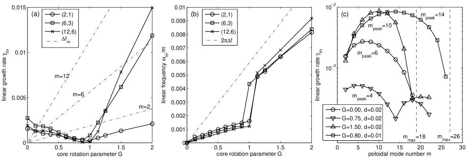
Results obtained by solving the linearized RMHD equations as an initial-value problem are presented in Figs. 2 and 3. In Fig. 2(a) the linear growth rates and in Fig. 2(b) the linear frequencies of several modes are plotted as functions of . Spectra of unstable modes are shown in Fig. 2(c) for several values of . The linear mode structures are shown in Fig. 3. The data were obtained with and , so the viscosity effect is negligible.Bierwage et al. (2005)
The curves in Fig. 2(a) are symmetric around (no flow), so only is considered. Since the distance is small, the resonances couple strongly and a broad spectrum of resistive DTMs with dominant high poloidal and toroidal mode numbers and are found for (cf. Refs. et al., 2005; Bierwage et al., 2005). In the range , the effect of the shear flow on DTMs is primarily a stabilizing one. However, it can be seen in Fig. 2(a) that this stabilization may stagnate and even reverse. For instance, the growth rate of mode rises briefly around before descending further. The origin of this behavior is not yet understood. The growth rates reach a minimum around and increase for almost linearly with . When a smaller velocity gradient () is used, or when the inter-resonance distance is increased, a larger value is obtained for (and vice versa). Without resonant surfaces () no unstable modes with helicity are found.
The frequencies in Fig. 2(b) undergo a shift around . For the rotation at the outer resonance determines the frequency of the mode. This is typical for DTMs (since typically ) and indicates that the current drive dominates in this regime. For the frequency equals that at the inner resonance, which is closer to the shear layer. Hence, is identified as the transition point between predominantly current-driven and shear-flow-driven modes. With a shear layer closer to the outer resonance there is no frequency shift.
A comparison between the growth rates and the effective shearing rates in Fig. 2(a) shows that increases with at least as fast as . This suggests that some of the coupling between the resonances, which is important for DTMs, may pertain even for . For the mode we have observed this effect by comparing the results of the RS configuration with results obtained with a monotonic profile with a single resonant surface and otherwise similar conditions: in the former case (RS) the shear-flow-driven mode is unstable [cf. Fig. 2(a)], in the latter case (monotonic ) it is stable. In contrast, higher- modes such as and have similar growth rates in both cases, so for these the coupling between the resonances does not seem to play a crucial role.
The full spectra of linear growth rates are shown in Fig. 2(c). For the same shear layer width as in Figs. 2(a) and (b) (half width ), the spectra are plotted for three values of : no shear flow (), stabilized (), and destabilized (). The dominance of modes with modes can be clearly seen. The DTM spectrum () has as its fastest growing mode and the last unstable mode is . In the stabilized case () has decreased to . In addition, a second branch of weakly unstable modes is present, with . For the frequencies of modes on both branches are determined by the rotation of the outer resonance. In the destabilized case (), the modes on the dominant branch around grow rapidly and their frequencies are up-shifted, implying rotation with the inner resonance. The growth rates on the secondary branch are almost the same as for and the frequencies are still determined by the rotation of the outer resonance.
In Fig. 2(c) a case with a smaller shear layer width is shown as well. Compared to the case, here the destabilization of shear-flow-driven modes has a lower threshold and the spectrum is broader: and . Indeed, it is found that is controlled by the parameter , while seems to be irrelevant. This is similar to KHI which possesses an upper threshold for the wave number of unstable modes:Chandrasekhar (1961) for it is required that . Here, for and the dominant branch has [Fig. 2(c)], so that . Modes on the secondary branch do not seem to be subject to the same threshold.
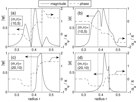
Calculations with magnetic Reynolds numbers in the range reveal that shear-flow-driven modes () on the dominant branch grow independently of . The ideal character of the instability is reflected in the linear eigenmode structures shown in Fig. 3(a) and (b) for : the flux perturbation switches signs at the resonances, as can be inferred from and the phase shifts [Fig. 3(a)]. The potential [Fig. 3(b)] is non-zero at the resonances and its complex phase exhibits a jump at the inflection point of the velocity profile, where . Resistivity independent modes are also observed with a single resonant surface and otherwise similar conditions.
The typical structure of modes on the secondary branch is shown in Fig. 3(c) and (d) for . The perturbation is localized between the shear layer () and the outer resonance (). At , the flux is non-zero and the potential has a discontinuity, suggesting a tearing-type instability. This mode grows most rapidly for , while the growth rate is reduced for larger and lower resistivity.
Further calculations show that the growth rates on the dominant branch are rather insensitive to the exact location of the shear layer between the resonances. This indicates that shear-flow-driven modes have a non-local character, in the sense that it is not sufficient to consider values of at the resonances only (cf. Ref. Tatsuno and Dorland, 2006).
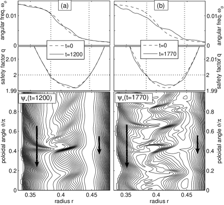
Finally, nonlinear simulation results are presented in Fig. 4 (parameters settings: , , , , single helicity , 128 modes, dealiased). At the time of the first snapshot, Fig. 4(a), the nonlinear mode coupling has reduced the velocity gradient around , while the profile in the surroundings is steepened. The helical flux contours show islands around the inner resonance, with a dominant topology and high- ripples. In the X-point regions, poloidally localized KHI-like vortices (only one shown due to -periodicity) can be observed. Subsequently, the islands undergo fragmentation and the structures become increasingly turbulent, as can be seen in the second snapshot in Fig. 4(b).
Note that the shear-flow-induced perturbations extend over the entire inter-resonance region (and beyond). Thus, one may expect a coupling similar to that in DTMs. Indeed, Fig. 4(b) shows island formation on both resonances while the central flux surfaces are still intact. Furthermore, in Fig. 4(b) a flattening of the flow profile in a wide region can be observed, while is still well below . This shows that when resistivity is low, the primary saturation mechanism in the early nonlinear stage is likely to be the flattening of the flow profile.
The observed magnetic reconnection is due to finite plasma resistivity rather than turbulence effects. However, there are two instability driving mechanisms, the current gradient and the velocity gradient, and it is not clear how much each contributes at a given time. The observed flattening of the flow profile suggests that the current-gradient-driven instability (i.e., DTM) may play a more significant role in later stages. The study of the long-time evolution of this system requires turbulence simulations which go beyond the scope of the physical model and numerical code used here.
In summary, we have analyzed the effect of sheared flows in a RS tokamak configuration when is below but close to a low-order rational value and a pair of nearby resonant surfaces has formed. The growth rates of DTMs are reduced, although the spectrum remains peaked at even with strong shear flow. For sufficiently strong velocity shear DTMs are replaced by a broad spectrum of shear-flow driven KH-like modes with dominant high . In the nonlinear regime and with finite resistivity, magnetic reconnection occurs near ripples caused by KH-like vortices. The tendency to develop turbulent structures in the inter-resonance region and flattening of the velocity profile is observed. Further calculations with experimental data as input are required in order to identify the role of KH-like modes in ITB discharges. Note also that since high- modes are involved the single-fluid MHD picture may be inaccurate. Our results motivate further investigations with more realistic models to understand the properties and effects of KH-like modes in tokamak plasma with ITB. Since high- modes are involved, we expect that similar instabilities may be found for other values of such as or .Bierwage et al. (2005)
A. B. thanks the Max-Planck-Institut für Plasmaphysik in Garching for its support and hospitality, and gratefully acknowledges valuable discussions with S. Hamaguchi, Z. Lin, E. Strumberger and T. Tatsuno.
References
- Chandrasekhar (1961) S. Chandrasekhar, Hydrodynamic and Hydromagnetic Stability (Clarendon Press, Oxford, 1961), Chapter XI.
- et al. (1998) R. E. Bell et al., Phys. Rev. Lett. 81, 1429 (1998).
- et al. (2004) J. W. Connor et al., Nuclear Fusion 44, R1 (2004).
- Levinton et al. (1998) F. M. Levinton, R. E. Bell, S. H. Batha, E. J. Synakowski, and M. C. Zarnstorff, Phys. Rev. Lett. 80, 4887 (1998).
- et al. (2000) S. Günter et al., Nucl. Fusion 40, 1541 (2000).
- Connor and Hastie (2004) J. W. Connor and R. J. Hastie, Phys. Rev. Lett. 92, 075001 (2004).
- Manickam et al. (1987) J. Manickam, N. Pomphrey, and A. M. M. Todd, Nucl. Fusion 27, 1461 (1987).
- Ganesh and Vaclavik (2005) R. Ganesh and J. Vaclavik, Phys. Rev. Lett. 94, 145002 (2005).
- Rogers and Dorland (2005) B. N. Rogers and W. Dorland, Phys. Plasmas 12, 062511 (2005).
- Tatsuno and Dorland (2006) T. Tatsuno and W. Dorland, Phys. Plasmas 13, 092107 (2006).
- Idomura et al. (2000) Y. Idomura, M. Wakatani, and S. Tokuda, Phys. Plasmas 7, 3551 (2000).
- Miura (2001) A. Miura, Phys. Plasmas 8, 5291 (2001).
- et al. (2005) A. Bierwage et al., Phys. Rev. Lett. 94, 065001 (2005).
- Bierwage et al. (2005) A. Bierwage, S. Benkadda, S. Hamaguchi, and M. Wakatani, Phys. Plasmas 12, 082504 (2005).
- Ofman (1992) L. Ofman, Phys. Fluids B 4, 2751 (1992).
- Dewar and Persson (1993) R. L. Dewar and M. Persson, Phys. Fluids B 5, 4273 (1993).
- Persson and Dewar (1994) M. Persson and R. L. Dewar, Phys. Plasmas 1, 1256 (1994).
- Yu (1997) Q. Yu, Phys. Plasmas 4, 1047 (1997).
- Strauss (1976) H. R. Strauss, Phys. Fluids 19, 134 (1976).
- Bierwage et al. (2006) A. Bierwage, S. Benkadda, S. Hamaguchi, and M. Wakatani, Phys. Plasmas 13, 032506 (2006).