Advances in ion back-flow reduction in cascaded gaseous electron multipliers incorporating R-MHSP elements.
Abstract
A new concept is presented for the reduction of ion back-flow in GEM-based cascaded gaseous electron multipliers, by incorporating Micro-Hole & Strip Plate (MHSP) elements operating in reversed-bias mode (R-MHSP). About an order of magnitude reduction in ion back-flow is achieved by diverting back-drifting ions from their original path. A R-MHSP/2GEM/MHSP cascaded multiplier operated at total gain of 1.5*105 yielded ion back-flow fractions of 1.5*10-3 and 4*10-4, at drift fields of 0.5 and 0.1 kV/cm, respectively. A 2R-MHSP/MHSP cascaded multiplier operated at a total gain of 105, yielded an ion back-flow fraction of 3*10-3. We discuss the concept for trapping back-flowing ions in these cascaded multipliers and the relevance to gaseous photomultiplier and TPC applications; directions for further future developments are outlined.
keywords:
electron multipliers (gas); avalanche induced secondary effects; charge transport and multiplication in gas; detector modeling and simulations II1 Introduction.
During the avalanche process in gaseous detectors, a large number of ions and photons are produced. In gaseous photomultipliers (GPM), their impact on the photocathode (PC) has high probability to induce secondary electron emission (SEE) and to generate secondary avalanches, known as ion- and photon-feedback. The secondary avalanches cause significant gain limitations and distortions of the spatial and temporal information. The photon feedback may be significantly suppressed by a proper choice of the electron-multiplier geometrical design and its operation conditions, and it is practically fully suppressed in cascaded GEM multiplier configurations [1, 2]. The ion backflow is much more difficult to suppress without affecting the multiplier gain and detection efficiency, because the ions’ and electrons’ paths are not decoupled. The ion backflow to the PC strongly limits the multiplier’s gain; e.g. gains 100 were measured in GEM-based visible-light sensitive GPMs due to the high emission properties of bialkali photocathodes, while they could attain 106 values when blocking the ions with a pulsed ion-gate electrode [3]. The back-flowing ions have further severe consequences, of physical and chemical damage to the PC surface and accelerated degradation of its quantum efficiency (QE) [3, 4, 5]. The ion backflow is also of great concern in Time Projection Chambers (TPCs), where the ion-cloud penetration into the drift volume builds up space-charge and causes rate-dependent dynamic electric-field distortions, consequently affecting the TPC resolution. Intensive research has been carried out to reduce this effect by replacing the standard wire-chamber TPC readout elements by cascaded GEM or Micromegas multipliers [6].
Though the demand to reduce ion backflow is common to TPCs and to GPMs, they differ in their operation conditions; TPCs typically operate at relatively low gain (104) and with low drift field above the multiplier (0.1-0.2 kV/cm) while GPMs have to operate at higher gain (105), to ensure single-photoelectron sensitivity, and with higher drift fields (0.5kV/cm), to provide efficient photoelectron extraction from the PC [7]. It should be noted that a 5-fold difference in drift field values generally implies a corresponding 5-fold higher ion backflow [8, 9]; the demands for ten-times higher gain and for full single photoelectron detection efficiency in GPMs imply further constrains in this case, as will be seen below.
The fraction of the last-avalanche induced ions flowing back to the drift volume or to the PC is defined here as Ion Backflow Fraction (IBF). The total number of electrons (and ions) created in the last avalanche in the cascade, per single initial electron (e.g. a photoelectron or a single ionization electron), is defined as the total gain of the multiplier. The number of electrons, per single initial electron, transferred from a given multiplier element on to a consecutive electrode is defined as the visible gain of that element.
In a single multi-wire or parallel-plate electron multiplier all the avalanche ions flow back to the cathodes, thus IBF=1. In cascaded-GEM structures some ions are trapped on GEM surfaces due to the dipole field within the GEM holes. It was shown [8] that the IBF in multi-GEM structures does not depend on the gas filling but rather on the detector’s geometry and on the electric fields configuration. The charge flow of both ions and electrons is reduced when choosing smaller GEM holes and smaller transfer fields between successive elements [8].In cascades comprising 3-4 GEM electrodes, it is possible to reduce the IBF by optimizing the hole diameter and shape as well as the transfer fields between the elements. The lowest IBF values reported so far, at total gas gain 104, are of the order of 0.05 and 0.01 at respective drift fields of 0.5 and 0.1kV/cm [8, 9].The lowest ones at higher gains, of 105, are 0.025 and 0.05 for 3 and 4 GEM-multiplier detectors correspondingly, at a drift field of 0.1kV/cm [10]. An operation of a 4-GEM detector with reflective PC on the top most electrode provided an IBF value of 0.1 at a gain of 105-106 [11]. It was recently reported [12, 13, 14] that a 3-GEM TPC readout element could be optimized as to have IBF=0.005 at a drift field of 0.2 kV/cm, by operating it in a highly asymmetric biasing mode: very high (8kV/cm) first and third transfer fields, very low (60V/cm) second transfer field and high bias voltage (350V) on the third GEM. This configuration was optimized for a total gain of 104 and it may not be adequate for higher gains, because some of the fields are already at their maximum possible value.
The IBF values presently reached in GPMs (with high total gain and high drift field [8, 10, 11]), of 10-2, are not sufficient for their DC operation with visible-light sensitive PCs; for such operation, considering the SEE probability of bialkali PCs, IBF10-4 is required. Furthermore, TPCs designed for future particle- and nuclear-physics collider experiments will operate at high drift fields (0.5-1 kV/cm) and will also require electron multipliers with IBF10-4, It is therefore clear that the current goal is an IBF10-4 and better for both GPMs and TPCs modes: in TPCs it will practically eliminate all ions in the drift region and in single-photon GPMs, operating at total gains of 105-106, it will reduce photocathode aging and ion-induced secondary avalanches to acceptable levels [15, 16]. As long as the IBF is not reduced to these levels, it constitutes a true obstacle in the further development of visible-light sensitive GPMs and calls for a thorough search for novel viable solutions for substantial IBF reduction.
An effective IBF suppression was already confirmed in TPCs [17] as well as in multi-GEM based photon detectors [3, 11], by means of an ion-gate electrode, which indeed suppresses the IBF to better than 10-4. However, ion gating often requires an external trigger source and involves electronic noise problems; it induces dead-time and thus rate-limitations, restricting its range of applications. We are therefore searching for ways to reduce the IBF in gaseous electron multipliers in DC mode.
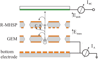
An attempt to do this by modifying the field configuration and thereby diverting a fraction of the ions away from the PC in a gaseous photomultiplier was done by replacing the last GEM in the cascade with a Micro-Hole & Strip Plate (MHSP) multiplier [18].The MHSP, like the GEM, is a hole-multiplier (Fig. 1); in addition it has narrow anode strips patterned on the bottom side, which under positive-voltage biasing provide a second avalanche multiplication, further to the one occurring within the electrode’s holes. The electric field established between the anode strips, the cathode strips and the additional cathode plane (2) prevents a large fraction ( 80%) of the final-avalanche ions from back flowing through the hole, as shown in [19]. Moreover, the two-stage multiplication of the MHSP enables further transfer-field optimization: by setting a small transfer field above the MHSP, the flow of both ions and electrons between the GEMs and the MHSP is reduced, but the loss in gain is recovered by the additional strip multiplication. Using such a scheme in a gaseous photomultiplier comprising 3-GEMs, a reflective CsI PC evaporated on the top GEM and an MHSP, the IBF was measured to be 0.03 at a total gain of 105 [19, 20]. This clearly demonstrated the potential for IBF reduction when using the MHSP electrode, by creating different paths for electrons and ions.
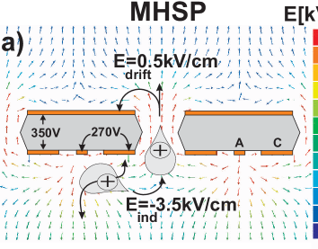
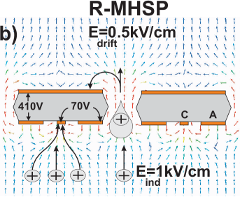
Following this line, it was further proposed [21] to reverse the roles of the MHSP′s anode and cathode strips, in an attempt to trap ions originating from consecutive multiplication elements in the cascade, preventing them to flow through the holes. 2 and 2 show the field configuration in the immediate proximity of the MHSP hole, for these two different modes of MHSP operation, defined here as the normal (MHSP) and the reversed (R-MHSP) modes (the arrows point at the field direction, namely to the ion drift direction). Note that in the normal MHSP mode, the narrow strip-electrodes act as anodes; they are biased more positive than the broader (cathode) strips surrounding the holes; in this case double-stage multiplication takes place within the holes and at the anode strips (2). In the reversed R-MHSP mode, the narrow strips are biased more negative than the broader ones; charge multiplication occurs only within the holes while the more-negative narrow cathode-strips only collect a fraction of the ions (2). The operation mode of the MHSP permits its use either as a stand-alone detector [18, 22] or as the last element in a cascaded multiplier [19]. On the other hand, the R-MHSP, with its hole-multiplication, can be used anywhere in the cascade, and especially as a first element, trapping back-flowing ions from all successive elements (as shown below).
However, one should be aware that in order to have full detection efficiency of single photoelectrons emitted from the photocathode, or of ionization electrons radiation-induced within the drift volume, two conditions have to be fulfilled: 1) the electron’s collection efficiency into the R-MHSP holes, particularly in the application to single-photon GPMs, has to be close to unity; this was indeed confirmed for GEMs [9, 23] but not yet for MHSPs, which have slightly more "opaque" hole geometry (Fig. 1); 2) the visible gain of the first element in the cascade should be large enough to ensure full event’s detection efficiency, including in the case of exponential pulse-height distribution of single photoelectrons; this condition implies a visible gain of at least 20. The two conditions are of prime importance, because an electron lost at the first multiplication element due to inefficient focusing, insufficient multiplication or inefficient extraction cannot be recovered. Indeed, it was found that the R-MHSP biasing scheme reduces the extraction efficiency of the avalanche electrons from the holes towards the next element in the cascade, thus reducing the visible gain of this multiplier [24].
A first attempt to implement the above ideas, cascading two R-MHSPs with two GEMs [24] resulted in an IBF value of 4*10-3, with a drift field of 0.5kV/cm and a total gain of 104. This study revealed, for the first time, that the ion trapping also results in a considerable loss of electrons (i.e. loss of visible gain) - necessitating a careful optimization of the operation conditions. In addition, this particular experiment was carried out with a defective R-MHSP electrode, of a limited hole multiplication; this resulted in a very low visible gain (only 6 electrons in average were transferred into the next GEM multiplication stage), and did not permit raising the strip voltages to fully exploit the possibility of ion trapping. Following the production of better quality MHSP electrodes we continued to study this avenue of IBF reduction. We will describe below the results obtained with different cascaded multiplier schemes combining GEM, MHSP and R-MHSP elements; the optimization of the R-MHSP potentials permitted reaching higher gains in the first multiplying element, and resulting in low IBF values with good single-electron detection efficiencies [3].
2 Methodology.
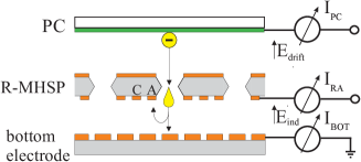
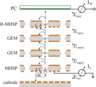
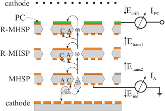
Four multiplier configurations investigated within this work are shown in Fig. 3; they combine a UV photocathode as a single-photoelectron source, a drift space with variable drift fields, electron multipliers and a readout anode. Fig. 3 depicts a single R-MHSP element coupled to a readout anode; It permitted investigating and understanding the role of the various potentials and to optimize their values. Fig. 3 shows a R-MHSP followed by a GEM; the GEM avalanche was used as an "ion generator" for studying the IBF suppression capability of the R-MHSP. The cascaded R-MHSP/2GEM/MHSP multiplier is shown in Fig. 3; this configuration permitted establishing the IBF value of this cascaded multiplier operating at high total gains, and using various drift fields corresponding to GPM and TPC operation conditions. In addition, a detector incorporating 2R-MHSPs followed by an MHSP is shown in Fig. 3; it represents a configuration with a reflective radiation converter, e.g. a UV-photocathode, deposited on the first element in the cascaded GPM.
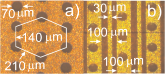
The MHSP and GEM electrodes, of 28x28 mm2 effective area, were produced at the CERN printed circuit workshop, from 50m thick Kapton foil with 5m copper cladding on both sides. The etched double-conical 70/50m outer/inner diameter GEM holes are arranged in hexagonal pattern of pitch 140m. The MHSP pattern and dimensions are shown in Fig. 1. All electrodes were stretched onto small MACOR frames. The semitransparent PC was 5mm in diameter; it was made of 300Å thick layer of CsI, evaporated on a UV transparent window, pre-coated with a 40Å thick Cr film.
The detector elements were mounted within a stainless-steel vessel evacuated with a turbo-molecular pump to 107 Torr prior to gas filling. The detector was operated with Ar/CH4 (95/5) at 760 Torr, under regulated gas flow. The detector was irradiated with a continuous Ar(Hg) UV-lamp through the window. Each of its electrodes was biased independently with a CAEN N471A or CAEN N126 power supply.
In all multiplier cascade configurations, the currents on biased electrodes were recorded as a voltage-drop on a 33M resistor with a Fluke 175 voltmeter of 10M internal impedance. Their combined resistance was 7.69M from which the anode current was calculated. The final avalanche-induced currents following charge multiplication were always kept below 100 nA by attenuating the UV-lamp photon flux with absorbers, if necessary, to avoid charging-up effects. The currents on grounded electrodes were recorded with a Keithley 485 picoamperemeter.
The IBF, visible gain and total gain were evaluated by recording currents from the various electrodes in the cascade, as described below for each of the configurations investigated. In particular: 1) the total gain in the R-MHSP/2GEM/MHSP detector was calculated from the ratio of the electron current on the anode of the last multiplying element (MHSP) to the PC photocurrent , measured in photoelectron collection mode (no gain): . The total gain derived from this currents ratio relates to the average multiplication factor; the number of electrons in an avalanche (and therefore the number of ions that hit the PC) is distributed according to a Polya function [26, 27, 28]. 2) The PC current recorded under multiplication conditions , comprises the photocurrent and the ion backflow current - the latter is by far dominant. Therefore, in the R-MHSP/2GEM/MHSP detector the ratio of to the MHSP anode current recorded under the same conditions , provides the IBF. The definitions are consistent with those of references [19, 24]. 3) the visible gain of the first R-MHSP element Fig. 3 is derived from the ratio of anode current , to the PC photocurrent , measured in photoelectron collection mode: .
3 Results.
3.1 Study of a single R-MHSP.
While the MHSP operation properties are already well established [19], those of the more recent R-MHSP [24] required some more basic study. The single R-MHSP study (Fig. 3, Fig. 3) was designed to yield understanding of the various potentials role and conditions for minimal IBF, minimal electron losses and maximal visible gain. The parameters affecting the R-MHSP′s operation are: 1) the hole bias voltage () which controls the multiplication and the IBF from the first element; 2) the anode-to-cathode strips voltage (), which reduces the visible gain of a single R-MHSP and reduces IBF from successive elements; 3) the transfer field below the R-MHSP ( in Fig. 3 or in Fig. 3, Fig. 3 and Fig. 3), which affects both the IBF from successive elements and the visible gain of the R-MHSP.
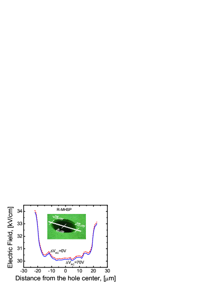
For simplicity, and since its influence is similar to that in cascaded GEMs (i.e. a linear increase of electron extraction efficiency with this field [25]), we fixed the field under the R-MHSP to be 1kV/cm. The drift field was maintained at 0.5 kV/cm (i.e. typical GPM operation conditions), which with Ar/CH4 (95/5) provides 70 efficiency to extract photoelectrons from the PC [7].At other values, the IBF increases linearly with the field [8] and thus a five-fold smaller IBF value is expected with = 0.1 kV/cm (i.e. TPC operation conditions).The exact collection efficiency (namely focusing into the holes) from the semitransparent PC into the R-MHSP holes, as function of the drift and hole fields (, ), extensively investigated for GEM cascades [23, 25] is a subject of another study, beyond the scope of the present article. An indication for high collection efficiency arises from 2, since there are no field lines that start at the R-MHSP top face, even though the figure corresponds to a cut made along the maximal hole distance. Furthermore, this efficiency can be roughly estimated, by comparison to studies in GEMs: since the holes of the R-MHSP are arranged in hexagonal pattern with maximal pitch of 210m, it is expected that the collection efficiency will be not worse than that of GEMs with identical hole diameter and pitch of 200m [25, 29], provided the same gas and the same and are used. The collection efficiency of a GEM, with a pitch of 200m and hole diameter 80m and 70m, acting as the first cascade element, were studied in conditions corresponding to operation with semitransparent PC [29] and reflective PC [25]. It was found that in Ar/DME (90/10) with a GEM-MWPC device preceded with a drift space, with hole voltage of 360V and drift fields in the range of 0.1-1kV/cm, the collection efficiency was of 90-100 [29]; with a GEM coated with a reflective PC, a collection efficiency of 90 was measured with hole voltage above 200V and drift field 0kV/cm in Ar/CH4 (95/5) [25]. Therefore, we may expect a collection efficiency 90 for our R-MHSP, when operating with semitransparent PC (=0.5kV/cm) at hole voltage 360V and with reflective PC (=0kV/cm) at hole voltage 200V.
Using MAXWELL 3D software package [30] we found for the R-MHSP (Fig. 4) that the field at the topside electrode, in the immediate proximity of the holes entrance, is not influenced by the voltage difference applied to the strips at the bottom-side electrode. This means that the electron transport and focusing into the R-MHSP holes is not affected by and should be studied only as function of and . As emphasized above, for efficient single-photoelectron detection the visible gain of the first R-MHSP should be carefully monitored. Taking into account that when is raised, only a few percents of the R-MHSP avalanche electrons are extracted to the next element, and that single-electron multiplication is exponential, we estimated that the first R-MHSP element should have a visible gain 20 in order to detect photoelectrons with good efficiency; the exact detection efficiency is a subject for future study, with pulse-counting method. Our current estimation is based on the avalanche-size distribution in single electron multiplication, which in general should follow Polya formula [26, 27, 28], but in the case of hole multiplication, in most gases [2], simplifies to an exponential distribution: , and are the number and the mean of electrons in a single-electron induced avalanche. With being the visible gain, , of the R-MHSP, we can calculate that for =20-25 there is 90-92 chance to have two electrons or more reaching the element following the R-MHSP, and these have high probability to be focused into its holes and be further multiplied and detected.
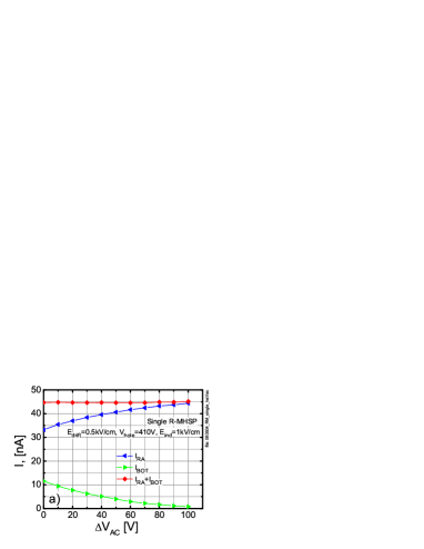
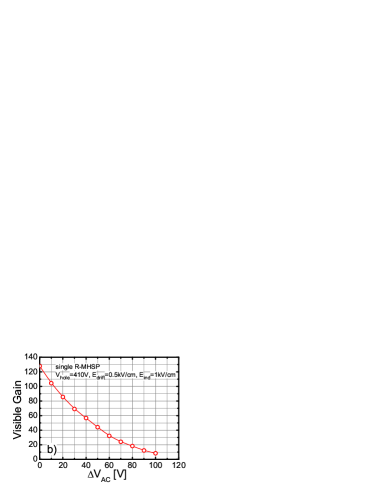
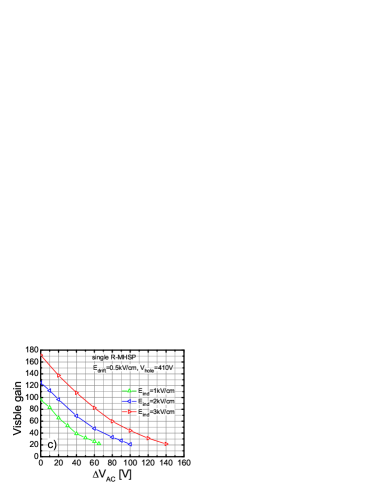
Fig. 5 shows the currents measured (setup of Fig. 3) on the R-MHSP anode strips , and on the bottom electrode , as function of the anode-to-cathode strips voltage, . was kept constant at 410V, resulting in avalanche gain in the holes 500, as derived from (the electron current on the cathode strip was nearly zero). and were kept at 1 and 0.5kV/cm, respectively. While the sum of both currents is constant, varying changes the current sharing between these two electrodes, namely the charge extraction from the R-MHSP holes to the next element (i.e. change of visible gain). As much as it is desirable to increase to divert more ions to the cathode strips, the drop in visible gain (Fig. 5) sets a limitation on this variable, at about 70V, corresponding to visible gain 25. This value could be further raised if the loss of electrons could be compensated by a further increase of , but from our experience =410V is already quite a high, though safe, operation voltage. Another possibility to maintain visible gain 25 with higher is by raising , as depicted in Fig. 5. The data in Fig. 5 confirms the well known [9, 25] linear dependence of the visible gain on the induction field. It should be noted that the data of Fig. 5 only were taken with an R-MHSP of smaller holes (50 microns), which explains the minor difference in visible gain compared to Fig. 5.
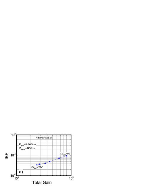
The IBF reduction capability of the R-MHSP was studied (Fig. 3) with an R-MHSP followed by a GEM, of which the avalanche acts as the source of back-flowing ions. The R-MHSP was biased at = 410V; the GEM was biased at 420V (gain 2000); the transfer field in the gap between them was =1kV/cm and the drift field was =0.5kV/cm. The total avalanche current in this configuration was measured as the sum of currents from the bottom anode and from the bottom GEM electrode. The IBF was calculated as the ratio of the PC current under multiplication, to the total avalanche current. 6 shows the IBF measured in these conditions, as function of the total gain of both elements; the latter was adjusted only by varying the voltage difference between the R-MHSP strips (). The IBF was reduced by a factor of 3 and the visible gain was reduced by a factor of 5 while raising from 0V (GEM-like mode) to 70V. In 6, the same IBF variation caused by raising , is shown for different transfer fields. With a higher transfer field the visible gain is higher and can be further raised: thus at =1kV/cm, was varied from 0V to 70V while at =2 and 3kV/cm, was raised to 100 and 240V, respectively; the maximal values correspond to R-MHSP visible gain of 25. However, as is obvious from 6, the IBF for different transfer fields is rather similar, and the best performance is with =1kV/cm.
3.2 R-MHSP/2GEM/MHSP cascaded multiplier.
The R-MHSP/2GEM/MHSP cascaded-multiplier configuration shown in Fig. 3 was chosen based on the reduced IBF with an MHSP as a last-stage MHSP [19] and its further potential reduction by an R-MHSP as a first element. Note, however, that their optimization are opposite and although in both operation modes the IBF reduces with increased strips voltage difference, in the MHSP this increase means higher total gain while in the R-MHSP it means lower visible gain. The optimized fields configuration suggested in [19] was combined with the insight from the R-MHSP study above, and we chose the following parameters (see Fig. 3): =0.5kV/cm; =1kV/cm; = =0.28kV/cm in order to suppress ion transport (though at the expense of electron transport suppression) and =-4kV/cm in order to collect ions at the bottom mesh cathode. The first R-MHSP voltages were: =410V; =70V following the results above. The GEM voltages were: ==280V, equivalent to a gain of 60 on each. The bottom MHSP voltages were: =300V between the top and cathode strip electrodes; we have varied on the bottom MHSP, to vary the total gain of the detector.
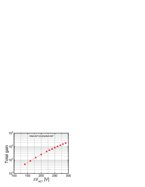
The total gain as function of on the bottom MHSP is plotted in Fig. 7. A charge multiplication of 50 was achievable on the anode strips of the bottom MHSP, by raising the strip voltage to 290V, in accordance with the results of [19].
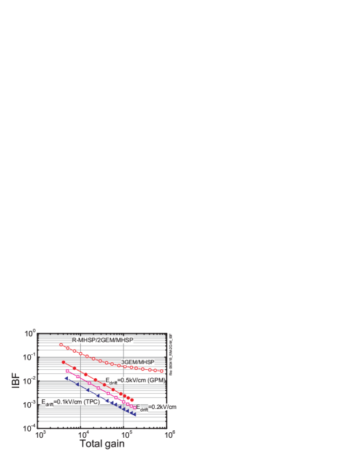
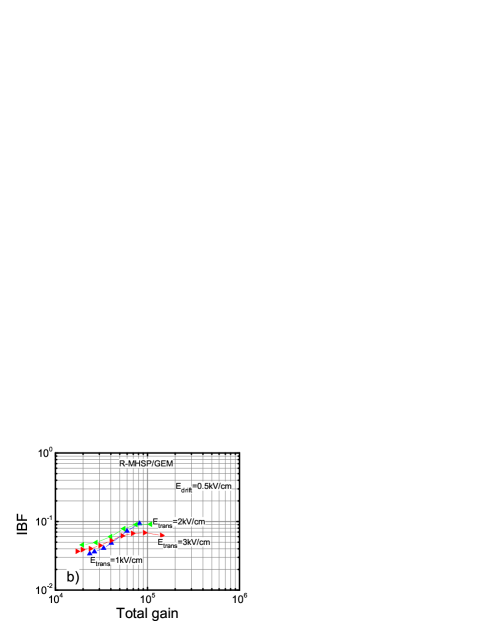
The recorded IBF is presented in Fig. 8 as function of the total gain, for drift-field values of 0.1, 0.2kV/cm (TPC conditions) and 0.5kV/cm (GPM conditions). In the GPM-like operation mode, the lowest IBF was 1.5*10-3 at a detector total gain of 1.5*105. It means that per a single-photon event, on the average 200 ions reach the PC. The IBF recorded at the same total gain in the TPC operation mode (drift field of 0.1kV/cm) is 4*10-4, which is 5 times lower, as expected from the linear dependence of IBF on the drift field discussed in [8]. At a drift field 0.2kV/cm the IBF is intermediate, of 7*10-4 at a total gain 1.5*105. Note that the IBF curves of the R-MHSP/2GEM/MHSP cascaded-multiplier (Fig. 8) drop as IBF=, being a constant, over the entire total gain range; this is in contrast with the case of the 3GEM/MHSP multiplier with reflective PC [19], shown for comparison in Fig. 8, where the IBF decreases slower than 1/ at total gains above 2*104. Based on the definitions of IBF (IBF=) and total gain (), it is clear that , which means that at a given drift field, the PC ion current is constant and does not increase with . In other words, all ions created at the anode strips of the MHSP do not reach the PC, which demonstrates full ion suppression by the electrode cascade preceding the MHSP strips. On the contrary, with the 3GEM/MHSP detector an increasing fraction of ions from the anode strips reach the PC, pointing at a poorer ion trapping capability of this cascade.
3.3 2R-MHSP/MHSP cascaded multiplier with a reflective PC.
An important configuration of cascaded gaseous photomultipliers is that with a reflective photocathode deposited on top of the first multiplying element, a GEM [25] or a THGEM [31]. In addition to the higher QE values of reflective photocathodes, in this configuration the sensitivity to ionizing-particle background is considerably reduced [25], because the gaseous drift gap is practically eliminated. The best IBF recorded so far in a reflective-PC GPM, of IBF=3, was in a 3GEM/MHSP configuration with the photocathode deposited on the top GEM [19]. We have investigated a few other solutions, among them a double R-MHSP followed by a MHSP, with a CsI photocathode deposited on the top R-MHSP [3] (Fig. 3).
The drift gap above the photocathode, defined by a mesh electrode placed at a distance of 3.5mm above the top surface of the R-MHSP (Fig. 3), was biased to have =0kV/cm, which according to [25, 31] provides the best photoelectron collection efficiency from the photocathode into the nearest hole. It was demonstrated that a slightly reversed field in this gap repels negative charges deposited there and significantly reduces the sensitivity to charged-particles background [32], at the expense of a minor (few percent) drop in photoelectron detection efficiency [25]. We studied the IBF under these conditions, with =-0.1kV/cm. In our experiment the potential across the hole of the first R-MHSP, =400V, ensured photoelectron extraction from the PC above 90; the anode-to-cathode strip voltage was set to be =50V and the first and the second transfer fields were set to rather high values, to provide a visible gain 20 for the first R-MHSP element and further good electron transfer to the last MHSP element:=3kV/cm and =5kV/cm; the induction field was =-8kV/cm; the second R-MHSP and the last MHSP were biased at rather high values of =450V and =430V across the holes, respectively. This however, allowed setting at the second R-MHSP to 100V for better trapping of ions from the last MHSP.
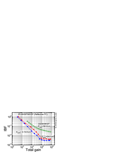
The IBF in the 2R-MHSP/MHSP detector with reflective PC is shown on Fig. 9 for two different drift fields: 0 and -0.1kV/cm (reversed field). The lowest IBF recorded is 3*10-3 in the total gain range of 105 - 7*105 (Fig. 9). The plots for both drift fields are nearly the same and start saturating at total gain 105. This, to our opinion, is due to non optimal operation conditions: 1) a too low at the first R-MHSP and 2) a too high compared to the value of 0.2-0.5kV/cm in [19]. However, the IBF values achieved in the present study are by an order of magnitude better than the best value obtained so far with 3GEM/MHSP detector + reflective PC [19], at a total gain of 105, shown for comparison in Fig. 9.
4 Conclusions and discussion.
In this work we have continued our long ongoing studies of IBF reduction in cascaded electron multipliers, searching for further improvements that will permit their operation with a visible-light sensitive (e.g. bialkali) PC. Following the 5-fold IBF reduction of the MHSP as a last cascade-element [19] and the preliminary results with the reversed-bias R-MHSP as a first cascade-element [24], we further studied the ion trapping properties of the R-MHSP. These were systematically investigated with R-MHSP as a stand-alone element, as a first element in a R-MHSP/2GEM/MHSP cascaded multiplier and in a reflective-PC gaseous photomultiplier based on 2R-MHSP/MHSP multiplier.
We found that raising the anode-to-cathode voltage in the R-MHSP from 0V (GEM mode) to -70V (R-MHSP mode) led to a 3-fold reduction of the IBF. We further evaluated the associated reduction in the visible gain of the R-MHSP first element and we argue that it can be maintained sufficiently high to ensure good detection efficiency of single-electron events: with hole multiplication 500, a transfer field 1kV/cm and anode-to-cathode voltage -70V the visible gain is 25, implying that in 92 of the events at least two electrons are transferred to the following element in the cascade.
The R-MHSP was investigated in an R-MHSP/2GEM/MHSP and 2R-MHSP/MHSP detector configurations, combining a CsI photocathode operated in semitransparent and reflective mode correspondingly. For the R-MHSP/2GEM/MHSP with a semitransparent PC, the drift field between the photocathode and the R-MHSP was selected to simulate GPM and TPC operation conditions. For the 2R-MHSP/MHSP detector with reflective PC, the drift field between the PC and the mesh was set either at 0kV/cm (corresponding to maximum photo-electron extraction from the PC) or slightly reversed (-0.1kV/cm), in order to decrease the detector’s sensitivity to charged-particles background.
4.1 GPM with semitransparent PC:
In the semitransparent-PC R-MHSP/2GEM/MHSP GPM, the IBF was found to be inversely proportional to the total gain; its best value in GPM-like mode (=0.5kV/cm), compatible with good single-electron detection efficiency, was 0.15 at a total gain of 1.5*105. This IBF is too high for a stable operation of the multiplier in combination with a visible-light sensitive photocathode (e.g. bialkali), due to the high emissivity of these photocathodes; for example, with a bialkali PC, the 225 ions (1.5*105 x 0.015) impinging on it per single-photoelectron event will induce on the average 8 secondary electrons [15, 16]. Thus at least an 8-fold IBF reduction is further required to bring the gain-limiting secondary avalanches to an acceptable level.
A further IBF reduction will also prolong the photocathode’s lifetime, affected by the ion impact. At present the photocathode lifetime of the R-MHSP/2GEM/MHSP GPM can be estimated, for example, from the recently measured aging rate of a bialkali PC: 20 loss of QE at an accumulated ion charge of 2C/mm2 on a K-Sb-Cs PC [3, 5]. With a photon flux of 1kHz/mm2 and a QE=30, such charge will be accumulated during 7 years of operation at a total gain of 105 and with IBF=2*10-3.
It should be noted that the IBF reduction with the present multiplier configuration is superior to that presented in our previous work [24]; it is a result of a better-quality MHSP electrodes and a combination of an R-MHSP and MHSP as first and last elements, respectively.
4.2 GPM with reflective PC:
In the reflective-PC 2R-MHSP/MHSP GPM the IBF was found to be 7-5 times lower than in the previously reported reflective-PC 3GEM/MHSP GPM [19], in the total gain range 105 - 106. It is in general more difficult to block the ions when using a reflective PC directly deposited on top of the hole-multiplier, because the field values and directions on this surface are dictated solely by the hole dipole filed, and under the large multiplication in the holes (dictated by gain considerations) this field is rather high [25]. Nevertheless, the R-MHSP as a first (and second) element indeed provides further IBF reduction.
4.3 TPC operation mode:
Due to the almost linear dependence of IBF on drift field, it is 5-10 times smaller in TPC operation mode compared to GPM one. In the R-MHSP/2GEM/MHSP detector and with =0.1kV/cm, the IBF is 4*10-3 and 4*10-4 at total gas gains of 1.5*104 and 1.5*105, respectively. It means that per single-electron multiplication event, 60 ions flow back to the drift region, independent of the gain.
The present study was motivated by the need to reduce the IBF in GPMs and therefore the structures under study were primarily adjusted for single-photoelectron detection conditions at high total gain (105). However, the majority of IBF studies [8, 12, 13] with multi-GEM detectors were carried out at lower gains (104), oriented towards TPC operation. With the presently studied multiplier configurations and fields, the IBF value in TPC-mode and at total gain 104 is practically not improved compared to the best results obtained so far with asymmetric 3-GEM cascade [12]. However, we expect that a better optimization of the R-MHSP/2GEM/MHSP multiplier in TPC-mode conditions (total gain 104 and =0.1kV/cm) will further reduce the IBF. On the contrary, at total gain 105, one order of magnitude improvement was achieved, compared to [19] as discussed above, and compared to [8] with a 3-GEM detector and =0.5kV/cm, reaching IBF=0.02 at total gain 6*104.
An idea to further reduce the IBF might be the use of single, or several R-MHSPs with anode and cathode strips patterned on both faces. According to our preliminary studies of an R-MHSP mounted with the strips facing the drift region (flipped R-MHSP), an increase of the anode-to-cathode voltage difference did not affect much the R-MHSP gain in the holes; in addition, the cathode strips, now facing the drift region, seem to efficiently capture the back-flowing ions from successive cascade elements. The results of these studies will be reported in another article.
Acknowledgements.
This work is partly supported by the Israel Science Foundation, grant No 402/05, by the MINERVA Foundation and by Project POCTI/FP/63441/2005 through FEDER and FCT (Lisbon). A. Breskin is the W.P. Reuther Professor of Research in The Peaceful Use of Atomic Energy.References
- [1] D. Mormann et al., GEM-based gaseous photomultipliers for UV and visible photon imaging, \hrefhttp://dx.doi.org/10.1016/S0168-9002(03)00760-5 Nucl. Instr. and Meth. A 504 (2003) 93.
- [2] A. Buzulutskov et al., The GEM photomultiplier operated with noble gas mixtures, \hrefhttp://dx.doi.org/10.1016/S0168-9002(99)01011-6 Nucl. Instr. and Meth. A 443 (2000) 164 and references therein.
- [3] A.Breskin et al., Ion-induced effects in GEM and GEM/MHSP gaseous photomultipliers for the UV and the visible spectral range, \hrefhttp://dx.doi.org/10.1016/j.nima.2005.08.005 Nucl. Instr. and Meth. A 553 (2005) 46 and references therein. [\physics0502132]
- [4] B.K. Singh et al., CsBr and CsI UV photocathodes: new results on quantum efficiency and aging, \hrefhttp://dx.doi.org/10.1016/S0168-9002(00)00485-X Nucl. Instr. and Meth. A 454 (2000) 364.
- [5] A. Lyashenko et al., Ageing studies of K-Cs-Sb PC under gas avalanche, (2006) in prepapration.
- [6] F. Sauli, Micro-pattern gas detectors, \hrefhttp://dx.doi.org/10.1016/S0168-9002(01)01903-9 Nucl. Instr. and Meth. A 477 (2002) 1.
- [7] A. Buzulutskov et al., GEM photomultiplier operation in CF4, \hrefhttp://dx.doi.org/10.1016/S0168-9002(01)01940-4 Nucl. Instr. and Meth. A 483 (2002) 670.
- [8] A. Bondar et al., Study of ion feedback in multi-GEM structures, \hrefhttp://dx.doi.org/10.1016/S0168-9002(02)01763-1 Nucl. Instr. and Meth. A 496 (2003) 325.
- [9] S. Bachmann et al., Charge amplification and transfer processes in the gas electron multiplier, \hrefhttp://dx.doi.org/10.1016/S0168-9002(99)00820-7 Nucl. Instr. and Meth. A 438 (1999) 376.
- [10] A. Buzulutskov et al., Sealed GEM photomultiplier with a CsI photocathode: ion feedback and ageing, \hrefhttp://dx.doi.org/10.1016/S0168-9002(01)01752-1 Nucl. Instr. and Meth. A 478 (2002) 225.
- [11] D. Mormann et al., Evaluation and reduction of ion back-flow in multi-GEM detectors, \hrefhttp://dx.doi.org/10.1016/j.nima.2003.08.156 Nucl. Instr. and Meth. A 516 (2004) 315.
- [12] S. Lotze et al., Charge Transfer of GEM Structures in High Magnetic Fields, \hrefhttp://dx.doi.org/10.1016/j.nuclphysbps.2004.07.005 Nucl. Phys. B (Proc. Suppl.) 150 (2006) 155.
- [13] F. Sauli et al., Ion feedback suppression in time projection chambers , \hrefhttp://dx.doi.org/10.1016/j.nima.2005.12.239 Nucl. Instr. and Meth. A 560 (2006) 269.
- [14] S. Roth et al., Charge transfer and charge broadening of GEM structures in high magnetic fields, \hrefhttp://dx.doi.org/10.1016/j.nima.2004.04.241 Nucl. Instr. and Meth. A 530 (2004) 251.
- [15] D. Mormann, Study of novel gaseous photomultipliers for UV and visible light, Ph.D. thesis, Weizmann Institute of Science, Israel.
- [16] D. Mormann et al., High gain operation of visible-sensitive gaseous photomultipliers, (2006) in preparation.
- [17] P. Nemethy et al., Gated time projection chamber, \hrefhttp://dx.doi.org/10.1016/0167-5087(83)90702-0 Nucl. Instr. and Meth. A 212 (1983) 273.
- [18] J. F. C. A. Veloso et al., A proposed new microstructure for gas radiation detectors: The microhole and strip plate, \hrefhttp://dx.doi.org/10.1063/1.1150623 Rev. Sci. Inst. A 71 (2000) 2371.
- [19] J.M. Maia et al., Avalanche-ion back-flow reduction in gaseous electron multipliers based on GEM/MHSP, \hrefhttp://dx.doi.org/10.1016/j.nima.2003.12.017 Nucl. Instr. and Meth. A 523 (2004) 334.
- [20] R. Chechik et al., Recent investigations of cascaded GEM and MHSP detectors, \hrefhttp://dx.doi.org/10.1109/TNS.2004.835628 IEEE Trans. Nucl. Sci. 51 (2004) 2097.
- [21] S. Roth et al., Charge transfer of GEM structures in high magnetic fields, \hrefhttp://dx.doi.org/10.1016/j.nima.2004.07.278 Nucl. Instr. and Meth. A 535 (2004) 330.
- [22] J. F. C. A. Veloso et al., MHSP in reversed-bias operation mode for ion blocking in gas-avalanche multipliers, \hrefhttp://dx.doi.org/10.1016/j.nima.2004.01.057 Nucl. Instr. and Meth. A 524 (2004) 124.
- [23] C. Richter et al., On the efficient electron transfer through GEM, \hrefhttp://dx.doi.org/10.1016/S0168-9002(01)00896-8 Nucl. Instr. and Meth. A 478 (2002) 38.
- [24] J. F. C. A. Veloso et al., MHSP in reversed-bias operation mode for ion blocking in gas-avalanche multipliers, \hrefhttp://dx.doi.org/10.1016/j.nima.2005.04.063 Nucl. Instr. and Meth. A 548 (2005) 375. [\physics0503237]
- [25] D. Mormann et al., Operation principles and properties of the multi-GEM gaseous photomultiplier with reflective photocathode, \hrefhttp://dx.doi.org/10.1016/j.nima.2004.03.212 Nucl. Instr. and Meth. A 530 (2004) 258.
- [26] J. Va’vra et al., Measurement of electron drift parameters for helium and CF4-based gases, \hrefhttp://dx.doi.org/10.1016/0168-9002(93)90970-S Nucl. Instr. and Meth. A 324 (1993) 113.
- [27] J. Va’vra, Photon detectors, \hrefhttp://dx.doi.org/10.1016/0168-9002(95)01138-2 Nucl. Instr. and Meth. A 371 (1996) 33.
- [28] N. Arley, Stochastic processes and cosmic radiation, John Wiley sons Inc., New York, (1948) p.98.
- [29] F. Sauli et al., New observations with the gas electron multiplier (GEM), \hrefhttp://dx.doi.org/10.1016/S0168-9002(97)00648-7 Nucl. Instr. and Meth. A 396 (1997) 50.
- [30] \hrefhttp://ansoft.com/products/em/max3d/ MAXWELL Commercial Finite Element Computation Package, Ansoft Co. Pittsburg, PA, USA.
- [31] R. Chechik et al., Advances in Thick GEM-like gaseous electron multipliers Part I: atmospheric pressure operation, \hrefhttp://dx.doi.org/10.1016/j.nima.2005.12.241 Nucl. Instr. and Meth. A 558 (2006) 475. [\physics0601115]
- [32] I. Tserruya et al., A hadron blind detector for the PHENIX experiment at RHIC, \hrefhttp://dx.doi.org/10.1016/j.nima.2005.02.039 Nucl. Instr. and Meth. A 546 (2005) 466.