Sagnac Effect in Resonant Microcavities
Abstract
The Sagnac effect in two dimensional (2D) resonant microcavities is studied theoretically and numerically. The frequency shift due to the Sagnac effect occurs as a threshold phenomenon for the angular velocity in a rotating microcavity. Above the threshold, the eigenfunctions of a rotating microcavity become rotating waves while they are standing waves below the threshold.
pacs:
03.65.Pm, 41.20.-q, 42.55.SaThe Sagnac effect is the phase difference between two counter-propagating laser beams in the same ring resonator due to rotation, originally introduced by Sagnac in 1913Post . It has become the basis for the operation of the optical gyroscopes such as ring laser gyroscopes and fiber optic gyroscopes after the invention of lasers and optical fibers in 1970’s Crow ; Aronowitz ; Vali ; Ezekiel because the phase and frequency difference between clockwise (CW) and counter-clockwise (CCW) propagating beams are proportional to the applied angular velocity. These optical gyroscopes are normally used in airplanes, rockets, and ships etc. since they are the most precise rotation velocity sensors among any other types of gyroscopes.
The Sagnac effect had been theoretically derived for the slender waveguides like optical fibers or the ring cavities composed of more than three mirrors by assuming that the light propagates one-dimensionally and the wavelength of the light is much shorter than the sizes of the waveguides or the ring cavitiesPost ; Crow ; Lamb2 . However, the sizes of the resonant cavities can be reduced to the order of the wavelength by modern semiconductor technologies Yamamoto ; Optical processes ; Nockel Stone . The conventional description of the Sagnac effect is not applicable to such small resonant microcavities. Especially, the resonance wave functions are standing waves which can never be represented by the superposition of counter-propagating waves. The assumption of the existence of CW and CCW waves plays the most important role for the conventional theory of the Sagnac effect.
In this Letter, by perturbation theory typically used in quantum mechanics, we show that the Sagnac effect can also be observed even in resonant microcavities if the angular velocity of the cavity is larger than a certain threshold where the standing wave resonance function changes into the rotating wave. It is also shown that numerical results of the quadrupole cavity correspond very well to the theoretical prediction. Theoretical and numerical approaches shown in this Letter do not assume that the CW and CCW waves exist in the cavity, but the pair of the counter-propagating waves is automatically produced by mixing the nearly degenerate resonance wave functions due to rotation of the cavity.
According to the general theory of relativity, the electromagnetic fields in a rotating resonant microcavity are subject to the Maxwell equations generalized to a non-inertial frame of reference in uniform rotation with angular velocity vector Post ; Crow ; Lamb2 ; Landau . By neglecting , we obtain the following wave equation for the electric field ,
| (1) |
where In the above, and are respectively the velocity of light and the refractive index inside the cavity.
In conventional theoretical approach for the Sagnac effect, the frequency shift of the resonance proportional to the angular velocity of the rotating ring cavity is derived from assuming that the electric field in Eq. (1) propagates one-dimensionally along the slender optical waveguidesCrow ; Lamb2 . This method is not applicable to the resonant microcavities because the wavelength of the resonance is not much shorter than the size of the cavity and the electric field does not propagate one-dimensionally.
Instead, in the case of the 2D resonant microcavity perpendicular to angular velocity vector , the resonances can be obtained by solving the following stationary wave equation derived from Eq. (1) for the stable oscillation solution,
| (2) |
where the 2D resonant cavity is rotating on -plane clockwisely,i.e., and . We assumed that TM mode of the electric field oscillates as .
For simplicity, we impose the Dirichlet boundary condition on the electric field of the resonant microcavity in the remainder of this Letter.
In the case of a microdisk cavity, Eq. (2) can be solved exactly as follows. Eq. (2) is rewritten in the following form in the cylindrical coordinates,
| (3) |
One can assume the solution is given as where is an integer, and then obtains
| (4) |
where
| (5) |
Eq. (4) is the Bessel differential equation, and so the solution should be the Bessel function of the m order . The eigenvalue of the wave number is given by the zero of because of the Dirichlet boundary condition, where is the radius of the microdisk cavity.
Accordingly, the shifted wave number due to rotation is
| (6) |
where is the zero of the Bessel function , that is, the eigenvalue of the wave number when the cavity is not rotating. Consequently, when the microdisk cavity is rotating, the wave function is the rotating wave and the degenerate wave number without rotation splits into two different wave numbers of the counter-propagating waves corresponding to the signs of the integer . From Eq. (6), one obtains the frequency difference between the counter-propagating waves,
| (7) |
It is important that the CW and CCW wave solutions are degenerate eigenstates even when the microdisk cavity is not rotating, and hence the standing wave solution produced by the superposition of these degenerate rotating waves are also the eigenfunction. However, with a finite angular velocity , the CW and CCW wave solutions become non-degenerate states, which means that only the rotating waves are the eigenfunction of the rotating microdisk cavity. The frequency difference between the CW and CCW solutions is proportional to the angular velocity . This is the Sagnac effect for microdisk cavities.
In general cases of 2D resonant microcavities of arbitrary shapes, Eq. (2) cannot be directly solved in the same way for microdisks.
First, we discuss the case that the spacing between the adjacent eigenvalues of the wave number is large enough to satisfy the following inequality,
| (8) |
where and are the wave functions of these eigenstates which correspond to the adjacent eigenvalues when the angular velocity is zero. We assume that, due to the rotation of the cavity, the eigenvalue is shifted as and the wave function is changed as where Here and are assumed to be so small as . Then, from Eq. (2) we obtain
| (9) |
Using the following relation,
| (10) |
where and denote respectively the domain and the edge of the cavity, we finally obtain up to the first order of , and
| (11) |
Consequently, as long as the angular velocity is small, there is no Sagnac effect, which means that the wave functions are standing waves instead of counter-propagating waves and the frequency difference between two standing waves does not increase.
Next we discuss the case that the spacing between two wave numbers and is so small that it does not satisfy the inequality (8). According to the perturbation theory for nearly-degenerate states in quantum mechanics, the wave function should be represented as the superposition of two nearly-degenerate eigenfuncions: Substituting this equation into Eq. (2) yields
| (12) |
where is the following matrix:
| (15) |
In order to obtain non-trivial solutions for Eq. (12), the determinant of should vanish, which yields a quadratic equation for . Consequently, we obtain the eigenvalues of the wave number up to the first order of ,
| (16) |
Accordingly, the frequency difference between the two eigenfunctions newly produced by rotation of the cavity is proportional to the angular velocityCorrespondence ,
| (17) |
Then, from Eq. (12) we also obtain the ratio of the coefficients and as follows:
| (18) |
It is important that the standing wave function without rotation of the cavity can be represented by the superposition of the Bessel functions as , if the cavity is symmetric for -axis and is an even function. The other wave function nearly degenerate to which should be an odd function for -axis also can be written as , where and . When the cavity is rotating but the angular velocity is small enough to satisfy the inequality (8), the frequency difference does not increase and the wave functions do not change drastically. However, when the angular velocity is increased to be larger than this threshold which violates the inequality (8), the wave functions change into the CW and CCW rotating waves because of Eq. (18),
| (19) | |||||
where the wave number is given by Eq. (16). Then, according to Eq. (17), one can observe the Sagnac effect as the frequency difference between counter-propagating waves proportional to the angular velocity. The most important point is that there is a threshold of the angular velocity for the Sagnac effect in resonant microcavities. It is possible to delete this threshold by symmetric shapes of the cavities as shown in the case of microdisks.
Next we numerically solve the Maxwell equation for a rotating microcavity, and show that the threshold phenomena of the transition from the standing wave solutions to the counter-propagating wave ones actually occur.
First, let us explain the numerical method briefly. The solutions for the Maxwell Equation (3) for the stationary solutions of the rotating cavity can be represented by the superposition of the Bessel functions in the cylindrical coordinates,
| (20) |
Then the Dirichlet boundary condition is imposed as , where denotes the edge of the cavity. Accordingly, we obtain
| (21) |
For numerical computation, the infinite sum over can be approximated by the finite sum from to where is a large integer. Then Eq. (21) can be rewritten as the matrix form,
| (28) |
where Therefore, the eigenvalues of the wave numbers can be obtained numerically as the zeros of the determinant of the above matrix because of non-trivial solutions for the coefficients .
For numerical calculation, we choose a quadrupole cavity, which is defined by the boundary Nockel Stone . The parameters of the quadrupole are set as follows: , and the refractive index . When the quadrupole cavity is not rotating, solving the Helmholtz equation Eq. (3) with yields the nearly-degenerate standing wave eigenfuctions as shown in Fig. 1. We call the two modes shown in Fig. 1(a) and (b) modes A and B, respectively.
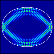 |
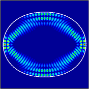 |
|---|---|
| (a) | (b) |

When the angular velocity is smaller than a certain threshold (where ), the frequency difference does not increase as shown in Fig. 2(a), and the eigenfunctions remain standing waves. However, for , the frequency difference increases gradually, and becomes proportional to , and modes A and B drastically change into the rotating wave functions as shown in Fig. 3(a) and (b), respectively.
The transition from the standing wave to the rotating wave can be clearly observed also by the CW and CCW wave components defined as follows based on rotating wave decomposition of Eq. (20):
| (29) |
where . For , are around 0.5 for modes A and B as shown in Fig. 2(b) and (c). When exceeds , of mode A(B) suddenly vanishes, which means the wave function consists of only CW(CCW) waves. Therefore, one can see that modes A and B in Fig. 3 are the CW and CCW rotating waves, respectively.
In summary, we have shown that the Sagnac effect can be observed in 2D resonant microcavities when the angular velocity is larger than a certain threshold where the nearly degenerate standing wave eigenfunctions of the non-rotating cavity change into the pair of the counter-propagating waves.
The threshold phenomenon seems to be akin to the lock-in phenomenon, which occurs owing to the mode-locking between the counter-propagating wavesCrow ; Aronowitz ; Lamb2 . However, in our theoretical approach, the effects of backscattering and an active medium which both cause the lock-in phenomenon are not taken into account. The existence of the threshold can be shown even without these effects.
The Sagnac effect in microcavities will be actually observable by measuring the frequency difference in a rotating frame of reference, as the measuring method of optical gyroscopes Crow ; Aronowitz . A discussion on the actual experiment will be reported elsewhere.
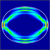 |
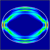 |
|---|---|
| (a) | (b) |
Acknowledgements.
The work was supported by the National Institute of information and Communication Technology of Japan.References
- (1) E. J. Post, Rev. Mod. Phys, 39, 475 (1967).
- (2) W. W. Chow, J. Gea-Banacloche, L. M. Pedrotti, V. E. Sanders, W. Schleich, and M. O. Scully, Rev. Mod. Phys. 57, 61, (1985).
- (3) F. Aronowitz, in Laser Applications, M. Ross, ed. (Academic, New York, 1971), Vol. 1, pp 133-200.
- (4) Vali V. and R. W. Shorthill, Appl. Opt., 15, 1099, (1976).
- (5) S. Ezekiel and S. R. Balsamo, Appl. Phys. Lett. 30, 478, (1977).
- (6) L. N. Menegozzi and W. E. Lamb, Jr. Phys. Rev. A, 8, 2103, (1971).
- (7) Y. Yamamoto and R. E. Slusher, Physics Today 46, 66 (1993).
- (8) R. K. Chang and A. J. Campillo, eds.: Optical processes in microcavities (World Scientific Publishing, Singapore, New Jersey, Hong Kong, 1996).
- (9) J. U. Nöckel and A. D. Stone, Nature 385,45 (1997).
- (10) E. Landau and E. Lifshits, The Classical Theory of Fields, 2nd ed. (Addison-Wesley, Reading, Mass., 1962)
- (11) Eq. (17) can reproduce a conventional expression for the frequency difference: by assuming that the light propagates one-dimensionally and the resonant modes in a non-rotating microcavity can be described as one-dimensional WKB solutions along an optical path. (In the above expression, A is the area bounded by the optical path and is the perimeter of the optical path.)