Parameters for a Super-Flavor-Factory
Abstract
A Super Flavor Factory, an asymmetric energy collider with a luminosity of order 1036 cm-2s-1, can provide a sensitive probe of new physics in the flavor sector of the Standard Model. The success of the PEP-II and KEKB asymmetric colliders KEKB ; PEP_II in producing unprecedented luminosity above 1034 cm-2s-1 has taught us about the accelerator physics of asymmetric colliders in a new parameter regime. Furthermore, the success of the SLAC Linear Collider SLC and the subsequent work on the International Linear Collider ILC allow a new Super-Flavor collider to also incorporate linear collider techniques. This note describes the parameters of an asymmetric Flavor-Factory collider at a luminosity of order 1036 cm-2s-1at the Y(4S) resonance and about 1035 cm-2s-1 at the production threshold. Such a collider would produce an integrated luminosity of about 10,000 fb-1 (10 ab-1) in a running year (107 sec) at the Y(4S) resonance. In the following note only the parameters relative to the Y(4S) resonance will be shown, the ones relative to the lower energy operations are still under study.
I Design from Past Successes
The construction and operation of modern multi-bunch colliders have brought about many advances in accelerator physics in the area of high currents, complex interaction regions, high beam-beam tune shifts, high power RF systems, controlled beam instabilities, rapid injection rates, and reliable uptimes (95%).
The present successful recent B-Factories have proven that their
design concepts are valid:
1) Colliders with asymmetric energies can work.
2) Beam-beam energy transparency conditions are weak.
3) Interaction regions with two energies can work.
4) IR backgrounds can be handled successfully.
5) High current RF systems can be operated (3 A x1.8 A).
6) Beam-beam parameters can reach 0.06 to 0.09.
7) Injection rates are good and continuous injection is done in production.
8) The electron cloud effect (ECI) can be managed.
9) Bunch-by-bunch feedbacks at the 4 nsec spacing work well.
Lessons learned from SLC and subsequent linear collider studies
(for ILC) and experiments (FFTB, ATF, ATF2) have also shown new
successful concepts:
1) Small horizontal and vertical emittances can be produced in
a damping ring with a short damping time.
2) Very small beam spot sizes and beta functions can be achieved
at the interaction region.
3) Bunch length compression can be successfully performed.
All of the above techniques can be incorporated in the design of a future Super-Flavor Factory (Super-B) collider.
II Design Status
The concept of combining linear and circular collider ideas to make a linear-circular B-Factory was discussed in the late 1980’s, although only circular B-Factories were built in the 1990’s. Recent advances in B-Factory performance and solid linear collider design progress has reopened this design avenue. The design presented here is very recent and on-going. The parameters presented here are preliminary but with the intent to be self-consistent.
III Luminosity
The design of a 1036 cm-2s-1 collider combines extensions of the design of the present B Factories and linear collider concepts to allow improved beam parameters to be achieved. The luminosity L in an collider is given by the expression
where is the number of bunches, is the frequency of collision of each bunch, is the number of particles in the positron (+) and electron (-) bunches, is the disruption enhancement factor from the collisions, is the beam size in the horizontal () and vertical () directions, is the beam emittance and is the beta function (cm) at the collision point for each plane.
IV Collider Concepts Studied at the First Super-B Workshop
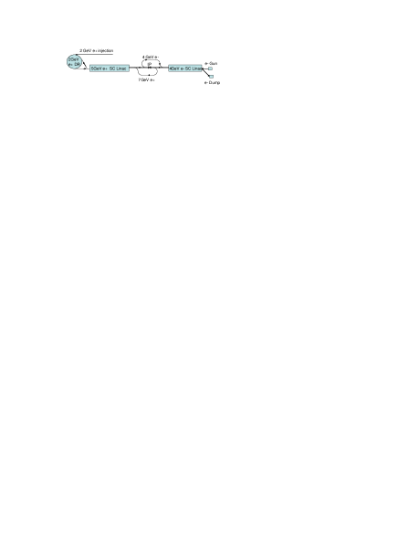
Schematic drawings of the Super-Flavor Factory as initially considered at the First Super-B workshop LNF is shown in Figure 1. The operation is described here. A positron bunch from a 2 GeV damping ring is extracted and accelerated to 7 GeV in a superconducting (SC) linac. Simultaneously, an electron bunch is generated in a gun and accelerated in a separate SC linac to 4 GeV. The two bunches are prepared to collide in a transport line where the bunch lengths are shortened. These bunches are focused to a small spot at the collisions point and made to collide. The spent beams are returned to their respective linacs with transport lines where they return their energies to the SC accelerator. The 2 GeV positrons are returned to the damping ring to restore the low emittances. The spent electron beam is discarded. The process is repeated with the next bunch. It is expected that each bunch will collide about 120 times each second and that there will be about 10000 bunches. Thus, the collision rate is about 1.2 MHz. A small electron linac and a positron source are used to replenish lost positrons in the colliding process and natural beam lifetime. See Figure 1.
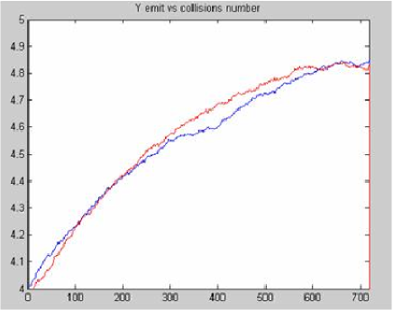
This scheme was necessary in order to save power for cooling the beams that are heavily disrupted after the collision. As shown in Fig. 2, the vertical emittance growth in a single collision is about 300. Running the rings at low energy is the only mean to bring the power requirements for the facility to the 100MW levels.
The scheme studied in LNF presents several complexities and challenging requirements for several subsystems. In particular the low energy required for the rings, in combination with the high current, low emittance, small energy spread and short bunch length, is more challenging than the already challenging solution studied for ILC. Moreover, several technical solutions proposed have never been tested and significant R&D and detailed studies, in order to ensure success, is required.
V Design Progress Presented at the Second Super-B Workshop
The IP parameters have been re-optimized in order to minimize the disruption due to the beam-beam forces. The proposed values, shown in Table 1, do produce a much smaller luminosity for a single pass, but the emittance blowup for a single crossing is of the order of a few parts in 103 and, thus, only modest damping is needed between collisions. The first column parameters are the best found so far for the previous scheme. The large energy spread at the IP due to the bunch compression is compensated with the monochromator scheme Dubrovin . Unfortunately, the requirements are extremely ambitious; the bunch charge is much bigger than the ILC one (a factor 3.5), the longitudinal emittance smaller (by factor 2) and the energy spread, together with the small at the IP is incompatible with the Final Focus bandwidth.
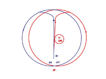
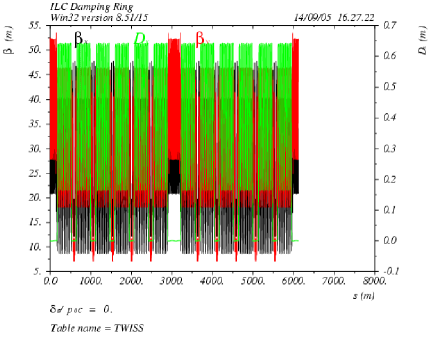
Fortunately, with the new scheme shown in Table 1 column 2 and with such small blowup, it is possible to increase the collision frequency, and collide continuously in the ring with near ILC requirements. The proposed parameters in the second column for the DR are nearly the ones proposed for ILC except the number of bunches is about 4 times larger. The required Final Focus is also exactly the one designed for ILC with the energy rescaled. In Fig. 3 is shown the schematic layout. Fig. 4 shows the optical functions of the ILC damping ring that operates at 5GeV and will be rescaled to 4 and 7 GeV.
| 1st LNF Workshop | 2nd LNF Workshop | |
| Best Working Point | Best Working Point | |
| (m) | 30 (1.0 betatron) | 2.67 |
| (mm) | 1.5 LER/–1.5 HER | 0.0 |
| (nm) | 12.6 | 12.6 |
| (mm) | 1.25 | 8.9 |
| (mm) | 0.080 | 0.080 |
| (mm) | 0.100 | 6.0 |
| (nm) | 0.8 | 0.8 |
| (nm) | 0.002 | 0.002 |
| (m) | 2.0 | 4.0 |
| (mrad) | Optional | 2*20 |
| (mm) | 4.0 | 6.0 |
| Npart () | 7.0 | 2.0 |
| Nbunches | 12000 | 12000 |
| I (A) | 6.7 | 1.9 |
| CDR (km) | 6.0 | 6.0 |
| (ms) | 10 | 20 |
| Nturns bet. Coll. | 50 | 1 |
| fcoll (MHz) | 12.0 | 650 |
| Lsingleturn () | 1.5 | 1.2 |
| Lmultiturn () | 1.1 | 1.0 |
VI Collision Parameters Optimization
Parameter optimization for this quasi-single pass factory has been performed with the criteria described in Section IV. Further studies and ideas could relax the critical requirements, and they will continue. The optimization for the “collisions in the ring” option is based on the requirements to not have any need for bunch compression and acceleration. The needs to have small IP spot sizes, small beta functions and tune shifts are satisfied with the combination of small emittances and a crossing angle. The low emittances reduce the beam sizes; the second one simultaneously reduces the tune shift in both planes Shatilov and the longitudinal overlapping region. Since the interaction region now is short, it is possible to decrease the vertical beta to very small values, further decreasing the vertical size and tune shift. In addition, further minimization of the beam-beam nonlinearities can be performed Raimondi , to greatly reduce the residual emittance blowup due to the crossing angle.
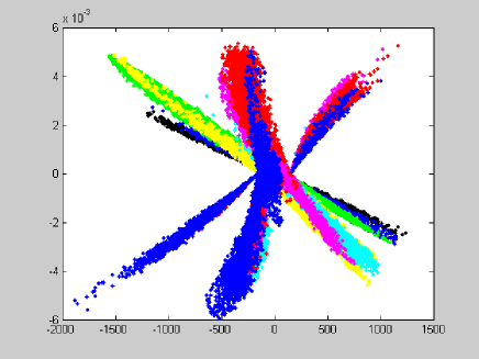
Beam-beam studies have been performed with the “GuineaPig” computer code by D. Schulte (CERN) Schulte , which includes backgrounds calculations, pinch effect, kink instability, quantum effects, energy loss, and luminosity spectrum. This code has been intensely used for ILC studies of beam-beam performances and backgrounds. In addition the code has been upgraded in order to evaluate the equilibrium parameters when the collisions occur repeatedly in a ring. The beams are tracked through the ring similarly to what is done in Cai , and the emittances and luminosity are evaluated after equilibrium is reached. Fig. 5 shows an example of such tracking.
VII Interaction Region Parameters
The interaction region is being designed to leave about the same longitudinal free space as that presently used by BABAR but with superconducting quadrupole doublets as close to the interaction region as possible Sullivan .
Recent work at Brookhaven National Laboratory on precision conductor placement of superconductors in large-bore low-field magnets has led to quadrupoles in successful use in the interaction regions for the HERA collider in Germany Parker . A minor redesign of these magnets will work well for the Super F Factory.
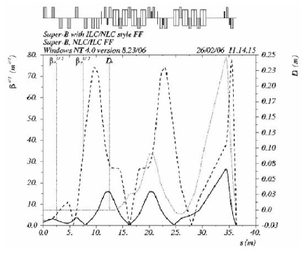
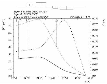
A preliminary design of the Final Focus, similar to the NLC/ILC ones, has been performed for the IP parameters in Table 1, second column. The total FF length is about 70 m and the final doublet is at 0.5m from the IP. Such a Final Focus needs to be inserted in one of the straight sections of the ring.
A plot of the optical functions in the incoming half of the FF region is presented in Fig. 6, optical functions in the final doublet is in Fig. 7.
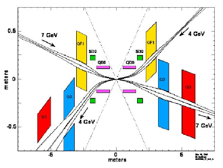
The need for a finite crossing angle at the IP greatly simplifies the IR design, since the two beams are now naturally separated at the parasitic collisions. An expanded view of a preliminary IR layout is shown in Fig. 8.
VIII Injector Concept and Parameters
The injector for the Super Flavor Collider will make up for lost particles with the finite beam lifetime in the damping rings and the losses from collisions. The injector will be similar to the SLAC injector delivering about 5 x 10¹⁰ electrons or positrons per pulse at about 40 Hz each.
IX Power Requirements
The power required by a collider is the sum of a site base and the accelerator operation. The damping ring power (about 40 to 60 MW) to replace the synchrotron radiation loss will be the dominant factor in this Super-B Factory. Better estimates and optimizations are under study.
X Synergy with ILC
There are many similarities between this linear Super-B collider and the ILC. The project described here will capitalize on R&D projects that have been concluded or are on-going within the ILC collaboration.
The damping rings between the two projects are now very similar. Main differences are the ring energies (5 GeV for the ILC-DR, 4 GeV and 7GeV for the Super-B) and the number of bunches (3000 for ILC, 12000 for Super-B). For the ILC the bunch number is mainly dictated by the LINAC requirements and the need to have enough spacing for the fast extraction scheme. These requirements are not needed for the Super-F. Another critical factor is the need to mitigate the electron cloud instabilities (ECI) in the positron ring. This problem will be more severe in the Super-F. ECI studies and R&D have to be performed for both the ILC and Super-F to mitigate this effect.
The interaction regions have very similar characteristics with flat beams and overall geometries. The ratio of IP beta functions are similar (8-30 mm horizontally and 0.08-0.5 mm vertically). The collimation schemes are comparable. The chromatic corrections of the final doublets using sextupoles will be the same.
All beam bunches will need bunch-by-bunch feedbacks to keep the beam instabilities and beam-beam collisions under control. With the bunch spacing very similar, the feedback kickers, digital controls, and beam impedance remediation will have common designs.
XI Other Upgrade Possibilities
The parameter optimization is continuously going on and we hope to further reduce the criticality of several machine constraints. In addition more careful studies are needed to make sure that the current constraints are valid.
Additional improvements are also being considered for this design. In particular we are studying the possibility to have a moderate bunch compression in the ring that could relax some of the parameters like emittances and beta functions.
The present scheme seems very promising but, given the rapid evolution of the concepts, it might still have some weak points that can jeopardize it. In addition new ideas and breakthroughs could also further change and improve the design.
It has also to be pointed out that with the present scheme the Super-B luminosity performance is a weak function with respect to the total length of the ring. It has been chosen to be 6km mainly for the synergy with ILC, but if there are strong constrains in terms of space and costs, it could be reduced together with a re-optimization of the other parameters.
Acknowledgements.
This document has come out of several recent Super-B workshops, with the most recent one being at LNF (Frascati, Italy) on March 16-18, 2006. We appreciate very much the useful discussions with the participants in these workshops. We also appreciate the discussions of the parameters with members of the ILC collaboration. This work was supported in part by United States Department of Energy contract DE-AC03-76SF00515.References
- (1) KEKB Status Report PAC 2005 Knoxville, TN.
- (2) PEP-II Status report PAC2005 Knoxville, TN.
- (3) The SLC Design Handbook, SLAC November 1984.
- (4) International Linear Collider Technical Review Committee, Second Report 2003, ICFA SLAC-R-606.
-
(5)
First LNF Workshop on SuperB, Frascati, Nov. 2005,
http://www.lnf.infn.it/conference/superbf05/. - (6) A. Dubrovin, A. Zholents, “A combined symmetric and asymmetric B-factory with monochromatization”, IEEE PAC 1991.
- (7) D. Shatilov, M. Zobov, “Tune shift in Beam.Beam collisions with an arbitrary crossing angle”, DANE Tech. Note G-59, May 1003.
-
(8)
P. Raimondi, 2nd LNF Workshop on Super-F, Frascati, 16-18 March 2006,
http://www.lnf.infn.it/conference/superbf06/. - (9) D. Schulte, “Study of electromagnetic and hadronic background in the Interaction Region of the TESLA Collider”, PhD Thesis, Hamburg, 1996.
- (10) Y. Cai, A. Chao, S. Tzenov, “Simulation of the bb effects in e+e- storage ring with a method of reduced region of mesh”, PRST, AB, Vol.4, 2001.
- (11) M. Sullivan, LNF Workshop on Super-F, Frascati, 16-18 March 2006.
- (12) B. Parker et al., “Superconducting Magnets for use inside the HERA ep Interaction Regions,” PAC 1999, New York, p. 308.