Correcting ray optics
at curved dielectric microresonator interfaces:
Phase-space
unification of Fresnel filtering and the Goos-Hänchen shift
Abstract
We develop an amended ray optics description for reflection at the curved dielectric interfaces of optical microresonators which improves the agreement with wave optics by about one order of magnitude. The corrections are separated into two contributions of similar magnitude, corresponding to ray displacement in independent quantum phase space directions, which can be identified with Fresnel filtering and the Goos-Hänchen shift, respectively. Hence we unify two effects which only have been studied separately in the past.
pacs:
05.45.Mt, 42.55.SaOver the recent years it has become feasible to design optical microresonators that confine photons by means of dielectric interfaces into a small spatial region not larger than a few micrometers YS93 ; VKLISLA98 ; QSTC86 . Two promising lines of research are the amplification of photons by stimulated emission in active media, which yields lasing action YS93 ; VKLISLA98 ; QSTC86 ; bowtie ; starofdavid ; sangwookkim ; morelasers ; morelasers2 ; koreaner ; japaner ; lebental , and the generation and trapping of single photons which can be used as carriers of quantum information photons . These applications require integration of several components and interfacing with electronics, which are best realized in two-dimensional resonator geometries where the main in- and out-coupling directions are confined to a plane, and can be selected via the (asymmetric) resonator geometry. Furthermore, because of the requirements of mode selection, these applications favor microresonators of mesoscopic dimensions, with size parameters (where is the linear size, is the wavenumber and is the wavelength) which quickly puts these systems out of the reach of numerical simulations. On the other hand, ray-optics predictions of the intricate resonator modes bowtie ; sangwookkim ; morelasers ; nature ; optlett_interf ; pre_annbill ; jan ; schwefel can deviate substantially from experimental observations starofdavid ; japaner and theoretical predictions starofdavid ; pre_annbill ; jan ; koreaner .
The purpose of this paper is to develop an amended ray optics (ARO) description which still idealizes beams as rays, but incorporates corrections of the origin and propagation direction of the reflected ray. We identify these corrections by utilizing quantum-phase space representations of the incident and reflected beam epl_husimi and relate them to the recently discovered Fresnel filtering effect ff and the long-known Goos-Hänchen shift ghs_entdeck . These two effects have only been discussed separately in the past (for applications to microresonators see, e.g., Refs. koreaner ; starofdavid ; chowdhury ; wir_pre ), and their complementary nature has not been realized. Moreover, their uniform analysis for all angles of incidence is known to pose considerable technical challenges ff ; ghs_lotsch ; ghs_lai ; branchpoints . In the phase-space representation, the Fresnel filtering and Goos-Hänchen corrections are simply determined by the position of maximal phase-space density. For the prototypical case of a Gaussian beam reflected from a constantly curved dielectric interface, we find that compared to conventional ray optics, the resulting ARO improves the agreement of the far-field radiation characteristics with wave optics by about one order of magnitude.
The plan of this paper is as follows. We first quantify the corrections to conventional ray optics by phase-space representations of the wave in the near field of the interface. Then we incorporate these corrections into an ARO. Finally, we test the ARO by its predictions for the far-field radiation characteristics.
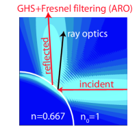
Conventional ray optics assumes that beams have well-defined propagation directions and a precise point of impact on a sharp dielectric interface, and predicts that an incident beam is reflected specularly and locally at the interface BornWolf . In two dimensions, deviations from ray optics at curved interfaces are apparent already at inspection of wave patterns such as shown in the left panel of Fig. 1, where the incident beam propagates from right to left. The wave pattern reveals that the reflected beam originates from a displaced position and propagates into a different direction than predicted by ray optics.
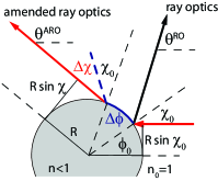
We choose a coordinate system with origin at the center of the circle of curvature (see the right panel of Fig. 1). This circle has the same radius of curvature as the dielectric interface and touches it tangentially at the point of incidence. The incident beam propagates into negative direction. For the comparison of wave optics to ray optics it is convenient to parameterize the rays by Birkhoff coordinates , where parameterizes the polar angle of the ray’s intersection point with the interface, while is the impact parameter of the ray, where is its angle of incidence. In this two-dimensional phase space, ray optics locates the incident and reflected rays in Fig. 1 both at the same point , , where furthermore for the present case that the incident ray is oriented into negative direction.
In wave optics, the corresponding two-dimensional Gaussian beam is described by the wavefunction
| (1) | |||
| (2) |
where are Hankel functions and is the width of the beam in the polar angle . Since we are interested in the corrections in leading order of , we assume that the curvature is locally constant. Then the reflected beam has the wavefunction
| (3) | |||
| (4) |
where denotes the Bessel function and is the refractive index on the other side of the interface.
In order to analyze the exact wave pattern in the phase space of Birkhoff coordinates we utilize Husimi representations in the near field of the dielectric interface. These Husimi functions are obtained by overlapping the incoming and reflected beam at the interface with a minimum uncertainty wave packet centered around epl_husimi ,
| (5) |
(a) incident, near field (b) reflected, near field
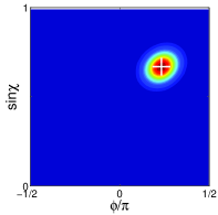
The Husimi phase-space representations of the wave pattern of Fig. 1 is shown in Fig. 2. The width of the incident Gaussian beam is chosen such that it yields an optimal approximation of a classical ray with comparable uncertainties in the propagation direction and the point of impact. This results in the almost-circular phase-space density in the left panel. The location of the maximal phase-space density corresponds well with the ray-optics prediction , indicated by the cross . The phase-space representation of the reflected beam is shown in the right panel. Clearly the position of the maximal phase-space weight of the reflected beam is displaced from the ray-optics prediction, as had to be expected from the inspection of the wave pattern in Fig. 1.
The displacement in direction can be explained by Fresnel filtering, which was introduced by Tureci and Stone ff ; starofdavid : A realistic beam has an uncertainty of its propagation direction which results in a spreading of the angle of incidence. The angle of incidence is further spread because of the curvature of the interface over the focal width . The Fresnel reflection coefficient displays an angular dependence which favors the reflection of wave components with a larger angle of incidence. This increases the beam’s angle of reflection, by an amount which we identify with the displacement
| (6) |
The displacement into direction can be interpreted as a Goos-Hänchen shift (GHS), first discovered for planar interfaces in 1947 ghs_entdeck (for recent works see Refs. koreaner ; ghs_phaseconj ; ghs_tran ; ghs_chauvat ; ghs_photcryst ). This shift arises from the penetration of the evanescent wave into the optically thinner medium ghs_lotsch ; ghs_lai . We identify the resulting lateral displacement of the reflection point along the physical interface with
| (7) |
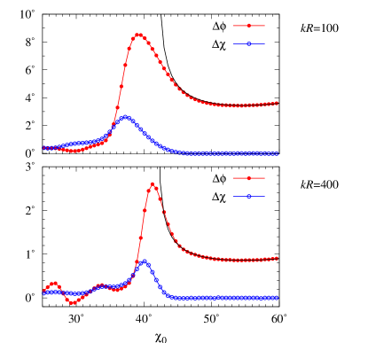
The angle-of-incidence dependence of and is shown in Fig. 3. Both corrections are most pronounced around the critical angle of incidence , and are sizeable effects even for rather large values of . Beyond the critical angle, approaches the classical result for the GHS by Artmann ghs_artmann ; ghs_lotsch , which is derived in the regime of total reflection at a planar interface.
ARO consists in propagation of the reflected beam with point of reflection given by and angle of reflection given by resulting in a propagation direction
| (8) |
(see the right panel of Fig. 1). Note that the corrections and both have been determined in the near field of the interface [see Eqs. (6,7)]. Hence, within the idealization of beams by rays, ARO agrees exactly with wave optics in the near field of the interface. The question is then whether the ARO ray parameters deliver accurate predictions also in the far field (where the beam may encounter another optical component or a detector). Hence, we now test the accuracy of ARO by examination of its predictions for the far-field radiation characteristics.
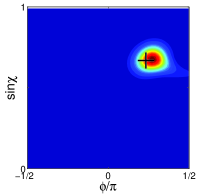
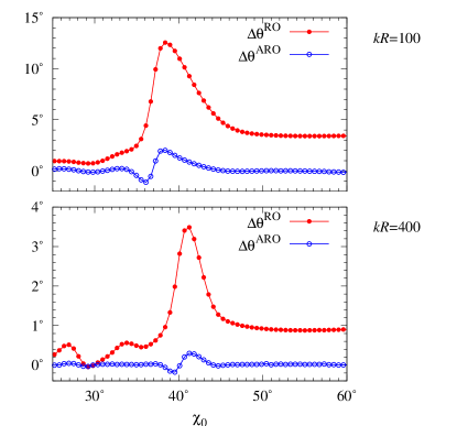
(a) incident, far field (b) reflected, far
field
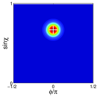
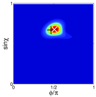
Figure 4 assesses these predictions for the wave pattern of Fig. 1 by means of Husimi phase-space representations of the incident and reflected beam in the far field of the interface,
| (9) |
In the far field, the phase-space coordinate coincides with the propagation direction , while is still related to the impact parameter (this coordinate is preserved because of angular-momentum conservation with respect to the center of the circle of curvature). The incident beam propagating into negative- direction is thus represented by phase space coordinates . Ray-optics predicts that the reflected beam has phase-space coordinates , where while ARO predicts that the reflected beam is located at ). The position of the maximal phase-space density of the reflected beam in the far field (right panel of Fig. 4) indeed corresponds well to the ARO prediction (indicated by ), but deviates distinctively from the ray-optics prediction (indicated by ).
In Fig. 5 the far-field radiation direction is analyzed as a function of the angle of incidence. One of the curves is the deviation of the observed radiation direction from the prediction of conventional ray optics. For , the maximal deviation is and occurs about below the critical angle of incidence. The plot also shows the deviation of ARO, . It is seen that ARO improves the agreement to close to the critical angle and agrees even better away from it. For larger size parameters , the maximal disagreement between ray optics and wave optics drops to and occurs at about below the critical angle of incidence. The ARO prediction agrees within around the critical angle, and the agreement is almost perfect away from it.
To summarize, we developed a systematically amended ray-optics description of the reflection of Gaussian beams from the curved dielectric interfaces of optical microresonators. This description incorporates the Goos-Hänchen shift of the reflection point along the interface and the Fresnel-filtering enhancement of the angle of reflection. The corrections were determined by analysis of exact wave-optical beams in a phase space where one coordinate is associated with the point of incidence or reflection along the interface, while the other one is related to the angle of incidence or reflection, respectively. Fresnel filtering and the Goos-Hänchen effect displace the reflected beam along independent phase-space directions. Hence, these displacements in principle exhaust all possibilities of amending ray optics while still keeping the basic assumption of propagation along straight lines in optically homogeneous media.
Amended ray optics is applicable to microresonators with smooth boundaries where the dimensionless radius of curvature is large, which is realized in most experiments. This includes the popular examples of multipole deformations bowtie ; starofdavid ; sangwookkim ; nature ; optlett_interf ; pre_annbill ; schwefel or stadium geometries japaner ; lebental ; morelasers . Complementary techniques exist to describe the diffraction of beams at sharp corners where formally diffraction ; see Ref. jan for an application to hexagonally shaped resonators VKLISLA98 . It remains to be seen whether both techniques can be interlaced to describe geometries which combine both curved interfaces and sharp corners morelasers2 ; koreaner ; moreover, whether both techniques can be unified in the challenging regime of a local curvature with .
We thank S.-Y. Lee, O. Legrand, H. Schwefel, R. Weaver, and J. Wiersig for discussions. This work was supported by the Alexander von Humboldt Foundation and the European Commission, Marie Curie Excellence Grant MEXT-CT-2005-023778 (Nanoelectrophotonics).
References
- (1) Y. Yamamoto and R. Slusher, Phys. Today 46, 66 (1993).
- (2) U. Vietze, O. Krauss, F. Laeri, G. Ihlein, F. Schüth, B. Limburg, and M. Abraham, Phys. Rev. Lett. 81, 4628 (1998).
- (3) S. X. Qian, J. B. Snow, H. M. Tzeng, and R. K. Chang, Science 231, 486 (1986).
- (4) C. Gmachl, F. Capasso, E. E. Narimanov, J. U. Nöckel, A. D. Stone, J. Faist, D. L. Sivco, A. Y. Cho, Science 280, 1556 (1998).
- (5) N. B. Rex, H. E. Tureci, H. G. L. Schwefel, R. K. Chang, and A. D. Stone, Phys. Rev. Lett. 88, 094102 (2002).
- (6) S.-B. Lee, J.-H. Lee, J.-S. Chang, H.-J. Moon, S. W. Kim, and K. An, Phys. Rev. Lett. 88, 033903 (2002).
- (7) T. Harayama, T. Fukushima, S. Sunada, and K. S. Ikeda, Phys. Rev. Lett. 91, 073903 (2003).
- (8) M. Lebental, J. S. Lauret, R. Hierle, and J. Zyss, Appl. Phys. Lett. 88, 031109 (2006).
- (9) T. Fukushima and T. Harayama, IEEE J. Sel. Top. Quantum Electron. 10, 1039 (2004); T. Fukushima, T. Harayama, and J. Wiersig, Phys. Rev. A 73, 023816 (2006).
- (10) V. Doya, O. Legrand, F. Mortessagne, and C. Miniatura, Phys. Rev. Lett. 88, 014102 (2001).
- (11) S.-Y. Lee, S. Rim, J.-W. Ryu, T.-Y. Kwon, M. Choi, and C.-M. Kim, Phys. Rev. Lett. 93, 164102 (2004).
- (12) Focus issue Single photons on demand, ed. P. Grangier, B. Sanders, and J. Vuckovic, New J. Phys. 6 (2004).
- (13) J. U. Nöckel and A. D. Stone, Nature 385, 45 (1997).
- (14) M. Hentschel and M. Vojta, Opt. Lett. 26, 1764 (2001).
- (15) M. Hentschel and K. Richter, Phys. Rev. E 66, 056207 (2002).
- (16) J. Wiersig, Phys. Rev. A 67, 023807 (2003).
- (17) H. G. L. Schwefel, N. B. Rex, H. W. Tureci, R. K. Chang, and A. D. Stone, J. Opt. Soc. Am. B 21, 923 (2004).
- (18) M. Hentschel, H. Schomerus, and R. Schubert, Europhys. Lett. 62, 636 (2003).
- (19) H. E. Tureci and A. D. Stone, Opt. Lett. 27, 7 (2002).
- (20) F. Goos and H. Hänchen, Ann. Physik 1, 333 (1947)
- (21) D. Q. Chowdhury, D. H. Leach, and R. K. Chang, J. Opt Soc. Am. A 11, 1108 (1994).
- (22) M. Hentschel and H. Schomerus, Phys. Rev. E 65, 045603(R) (2002).
- (23) H. K. V. Lotsch, Optik 32, 116 (1970); 189 (1970); 299 (1971); 553 (1971).
- (24) H. M. Lai, F. C. Cheng, and W. K. Tang, J. Opt. Soc. Am. A 3, 550 (1986).
- (25) L. B. Felsen and N. Marcuvitz, Radiation and Scattering of Waves (IEEE Press, New York, 1994); L. M. Brekhocskikh, Waves in Layered Media (Academic Press, New York, 1980).
- (26) M. Born and E. Wolf, Principles of Optics (Cambridge University Press, New York, 1999).
- (27) N. H. Tran, L. Dutriaux, P. Balcou, A. Le Floch, and F. Bretenaker, Opt. Lett. 20, 1233 (1995).
- (28) B. M. Jost, A.-A. R. Al-Rashed, and B. E. A. Saleh, Phys. Rev. Lett. 81, 2233 (1998).
- (29) D. Chauvat, O. Emile, F. Bretenaker, and A. Le Floch, Phys. Rev. Lett. 84, 71 (2000).
- (30) D. Felbacq and R. Smaâli, Phys. Rev. Lett. 92, 193902 (2004).
- (31) K. Artmann, Ann. Physik 8, 270 (1951).
- (32) H. M. Nussenzveig, Diffraction Effects in Semiclassical Scattering (Cambridge University Press, Cambridge, 1992); M. V. Berry and K. E. Mount, Rep. Prog. Phys. 35, 315 (1972).