EUROTeV-Report-2006-022
\subject
Improved final doublet designs for the ILC baseline small crossing angle scheme
Abstract
The ILC baseline consists of two interaction regions, one with a 20mrad crossing angle and the other with a 2mrad crossing angle. It is known that the outgoing beam losses in the final doublet and subsequent extraction line are larger in the 2mrad than in the 20mrad layout. In this work, we exploit NbTi and Nb3Sn superconducting magnet technologies to redesign and optimise the final doublet, with the aim of providing satisfactory outgoing disrupted beam power losses in this region. We present three new final doublet layouts, specifically optimised for the 500 GeV and the 1 TeV machines.
1 INTRODUCTION
The current baseline configuration of the International Linear Collider [1] consists of two interaction regions (IRs) and two detectors, with one IR having a large beam crossing angle and one having a small beam crossing angle. The large crossing angle layout has an angle of 20mrad between the beams, and is derived from the large crossing angle design of the Next Linear Collider [2]. Its optical properties are well understood, and the extraction line successfully transports the disrupted beam to the dump, for a wide range of proposed beam parameter sets [3]. Furthermore, the design includes downstream diagnostics for energy and polarisation measurement. The 2mrad interaction region layout presents more technical challenges, mainly resulting from transporting the outgoing disrupted beam off-axis in the final doublet. This design is more recent and the first complete optics was presented at Snowmass 2005 [4]. This layout was developed for 1 TeV using NbTi superconducting final doublet magnets and included downstream energy and polarimetry measurement chicanes.
The current ILC parameter space is documented in [5] and the key parameters are listed in Table 1. These consist of sets of representative beam parameters, designed to assure flexibility in case of unexpected practical limitations in achieving some of the machine goals. The most challenging of these sets is known as the High Luminosity set, which aims to maximise the instantaneous luminosity by more strongly focusing the beams at the IP, thereby significantly enhancing disruption effects. A necessary criterion for the performance of the extraction line design is its ability to accommodate the broadest possible range of beam parameters. The 20mrad scheme is successful for the majority of parameter sets, but the current (baseline) 2mrad design shows unacceptable beam power loss, both in the final doublet and in the extraction line, for some of the beam parameters considered.
In this work, we exploit the limits of current magnet technology as well as technology still under development to optimise the 2mrad final doublet layout. We present three new final doublet designs, one optimised for the baseline energy of 500 GeV and two for the upgrade energy of 1 TeV. We optimise the magnet parameters with respect to power deposition from charged beam and radiative Bhabha particle losses, with the goal of accommodating all ILC beam parameter sets. We find that this is possible by using NbTi technology for the 500 GeV machine, and by using new Nb3Sn technology for the 1 TeV upgrade. However, an increase in pole tip field, somewhat beyond the currently planned limits for Nb3Sn technology, would be required to achieve power losses small enough to avoid quenching of the final doublet magnets for the case of the Low Power and High Luminosity beam parameters at 1 TeV. We include a full set of magnet and optical parameters for evaluation by magnet designers.
In Section 2 we discuss the available magnet technologies and the constraints we place on magnet parameters. We describe our final doublet optimisation procedure in Section 3 and present the resulting magnet parameters for each case. The beam transport and resulting losses with our new doublets are presented in Section 4, and we draw our conclusions in Section 5. We find that the proposed new final doublet layouts have considerably better beam transport properties than the current ones.
| Set | Energy | Nb | Iav [A] | [m-2 s-1] | |
|---|---|---|---|---|---|
| Nominal | 500 GeV | 2820 | 0.0104 | 0.022 | 2.03E38 |
| Low Power | 500 GeV | 1330 | 0.0069 | 0.057 | 2.05E38 |
| High Lum. | 500 GeV | 2820 | 0.0104 | 0.070 | 4.92E38 |
| Nominal | 1 TeV | 2820 | 0.0104 | 0.050 | 2.82E38 |
| Low Power | 1 TeV | 1330 | 0.0069 | 0.134 | 2.92E38 |
| High Lum. | 1 TeV | 2820 | 0.0104 | 0.178 | 7.88E38 |
2 MAGNET PARAMETERS
2.1 Current baseline design
The final doublet in the 2mrad scheme is based a superconductive large bore QD0 magnet and on a normal conducting smaller aperture QF1 magnet. The two nearby sextupoles for local chromaticity correction, SD0 and SF1, are also superconductive large bore magnets. In the current design, the choice of superconductive technology for QD0 is NbTi and the maximum pole tip field which is assumed to be achievable is 5.6 T. In this work we always take l∗ to be 4.5m and the QD-QF distance to be 9m. The outgoing beam passes through the coil pocket of QF1, where the field is modelled by a standard multipole expansion. The outer coil radius, which is available for beam passage, is 115mm. In this design, the doublet was optimised for the TeV machine, and the 500 GeV layout was obtained by scaling down the fields.
2.2 Maximum pole tip field for NbTi
For the NbTi magnets [6] considered in this work, we assume a maximum pole tip field of 6.28 T. This is around the maximum field that current coil designs can produce, and includes the field-reducing effects of the external solenoid and a safety magin [7]. This corresponds to a gradient of 180 T m-1 in a magnet of radial aperture 35mm. The sextupoles are required to be large bore superconducting magnets, to allow the transport of the outgoing beam. We follow the technology choice of the current design, and adopt a maximum field of 4.04T in SD0 and SF1 (with radial apertures of 88mm and 112mm, respectively)111The maximum field in a sextupole probably has some dependance on its aperture. This point should be checked with experts, to assess the feasibility of our proposed magnets..
2.3 Expected maximum pole tip field for Nb3Sn
We also propose to use Nb3Sn-based technology [6] for QD0 at 1 TeV. The higher gradient permitted by this magnet will improve the beam transport properties of the doublet, by allowing a more compact design. These magnets have yet to be proven, but in the timescales of the ILC TeV upgrade, should hopefully be readily available222The development of superconductive magnets based on Nb3Sn technology is also being strongly stimulated by the LHC luminosity upgrade programme, which also requires higher gradients for its low-beta insertion quadrupoles.. Of course, such an upgrade would require replacing the final doublet, but this is rather minor on the scale of the 1 TeV energy upgrade. Furthermore the geometry of the extraction line would need to be maintained. The maximum pole tip field which we assume will be achievable with Nb3Sn is 8.8T (taking into account the presence of a solenoid background field). This corresponds to a 250 T m gradient for a 35mm radial aperture.
2.4 Outline of doublet designs
In this work, we propose three new doublet layouts. We shall optimise the layout for the 500 GeV machine, using NbTi for QD0 at a maximum pole tip field of 6.28 T. The beam transport properties of such a layout will be considerably better that the scaled down version of the 1 TeV existing baseline, because the magnet length can be reduced. The sextupoles shall be optimised versions of the current baseline. We shall then calculate the layouts for the TeV machine, firstly using NbTi for QD0 as the design for 500 GeV, and secondly with Nb3Sn. The resulting doublets are intended to replace the present design.
The current baseline magnets are summarised in Table 2. In Table 3 we describe our proposed magnet technology limits for this work.
| Magnet | Length | Strength | radial aperture | gradient | BPT |
|---|---|---|---|---|---|
| QD0 | 2.5m | -0.0958 m-1 | 35mm | 159.4 T m-1 | 5.58 T |
| SD0 | 3.8m | 0.6254 m-2 | 88mm | - | 4.04 T |
| QF1 | 2.0m | 0.0407 m-1 | 10mm | 67.8 T m-1 | 0.68 T |
| SF1 | 3.8m | -0.2039 m-2 | 112mm | - | 2.13 T |
| Magnet | Type | Maximum field |
|---|---|---|
| QD0 (NbTi) | SC | 6.28 T |
| QD0 (Nb3Sn) | SC | 8.75 T |
| SD0 | SC | 4.04 T (r=88mm) |
| QF1 | NC | 1.02 T |
| SF1 | SC | 2.13 T (r=112mm) |
2.5 Assumed power deposition tolerances
Superconductive magnets will quench if too much beam power is deposited in them, and both integrated power and localised power density tolerances have been specified by the CERN group for the LHC quadrupoles used in this work. The maximum integrated power which can be tolerated per unit length is in the range 5-10 W m-1. However, for a few specific magnets like those in the final doublet, this tolerance can presumably be relaxed a bit if more cryogenic power can be used. The highest localised power density which can be accepted is 0.5 mW g-1. This tolerance is important to consider in this work because the outgoing beam is transported off-axis through several of the final doublet magnets, and so particles at the lower end of the energy distribution can get over-focused onto the edge of the magnet aperture on one side. Since these particles are essentially concentrated in a plane (except for their vertical angular spread), the local power density can become high. We rely on detailed computations performed at RHUL with the GEANT-4 based BDSIM simulation [8], following similar calculations at SLAC [9]. These calculations have shown that for about 1 W incident beam power on the edge of QD0, a maximum power density of about 4 mW g-1 can be reached inside the NbTi coils. If a 3 mm Tungsten liner (corresponding to about 1 radiation length) is used to thicken the beam pipe and spread out the showers at the location of the loss, the maximum power density can be brought down to about 0.3 mW g-1 in the same conditions. Based on these numbers, we use 1 W as the maximum value for the power deposited on the edge of QD0. This 1 W 0.3 mW g-1 equivalence, found between total incident power and power density in QD0, will have to be checked for other magnet configurations and beam parameters, especially in the case of the sextupoles.
3 FINAL DOUBLET OPTIMISATION
In this section, we shall discuss our optimisation of the final doublet layout. We shall start with the optimisation of QD0. Several studies of the power deposition into QD0 have shown that the charged beam loss and the loss from radiative Bhabhas exceed the quench limits of the coils, for some of the proposed beam parameters. Therefore, the goal of our optimisation is to reduce these losses to acceptable levels, for all beam parameters. Note that we work in terms of total incident power, and consider the conversion to localised losses separately (see Section 2.5). The optimisation procedure described in the following is applied to all three final doublet designs outlined in Section 2.
The underlaying principle is, in the first instance, to make the magnet as short as possible within the constraints of the available pole tip field. Hence we begin by increasing the field of QD0 to the maximum possible value, and decrease the length in proportion.
We then perform a scan of the aperture and pole tip field, adjusting the length to maintain the overall focusing strength, and using the total power deposition from the different beam parameter sets as figure of merit. The magnitude of the beamstrahlung energy loss for the Low Power and High Luminosity beam parameters it such that these sets dominate the optimisation. Both the effects from the charged beam, for vertical offsets at the interaction point maximising the beamstrahlung losses, and the combined effects of radiative Bhabhas and the charged beam (collided in this case without a significant vertical offset) are considered. We generally find a mimimum in the total power deposition which is very similar for all parameters sets, as the dependance of the total power versus aperture and length found from the scanning is rather shallow. This procedure allows a power-optimised QD0 length, aperture and pole tip field, with the constraints of maintaining the constant integrated focusing strength needed to achieve the required demagnification and keeping the pole tip below a given assumption on the maximum value achievable. Note that the former constraint maintains the demagnification of the final telescope, and also maintains the integrated strength of QF1. To ensure that the mimimum we reach in the 3-dimensinal space of the scan is a true and global minimum, we begin with a variety of initial magnet conditions (i.e. origin in our space). We find that we always converge to the same point in all cases. We perform this optimisation for the three cases we consider in this work and the result is a set of three QD0-QF1 systems.
Once QD0 has been optimised, we can fit for the local chromaticity correction sextupoles. For these sextupoles, located in the immediate vicinity of the final doublet quadrupoles, we assume the same maximum pole tip fields as in the baseline. The chromaticity is corrected, and the required sextupole strengths calculated, by using a simplified model of the system, consisting of the final doublet region and two upstream bends to generate the required dispersion. The bend strengths are fitted to give and at the interaction point. Note that the latter value is chosen to give acceptable sextupole strengths, whilst maintaining the beam angular divergence close to its intrinsic value. While a full treatment of the final focus chromaticity correction includes the condition of zeroing the and matrix element across the full system, it has been shown that, to a good approximation, sextupole strengths consistent with those in such a full treatment can be obtained by zeroing the and matrix elements across the simplified system [10]. We apply such a procedure to compute the sextupole strengths in this work. The inter-magnet distances chosen are shown in Table 4. In this work, the optics code MAD [11] was used to compute the chromaticity correction.
The length of the optimised sextupoles was chosen to give a reasonable starting point for the beam transport. The sextupole lengths are hence not fully optimised, and require some further study. To optimise the sextupole apertures, a fit is performed, within the maximal value assumed for the pole tip fields, and requiring no loss when transporting a Nominal, Low Power or High Luminosity beam. The inter-magnet spacings were optimised for beam transport. The technological constraints limit the maximum aperture, and we fit the aperture by requiring no loss when transporting a nominal, low power or high luminosity beam. The available aperture is computed from the quadratic rise of the field in the beampipe of the sextupole. Note that we consider both the radiative Bhabha contribution to the power deposition and the effect of a vertically offset beam. The requirement of small enough loss (1 W in total) is very stringent, particularly in the case of the High Luminosity offset beams, and results in large sextupole apertures. These could be considerably reduced by relaxing the beam transport requirement, for instance if one would avoid beam parameter optimisations with very large beamstrahlung energy losses.
The results of the optimisation can be found in table 5 for NbTi at 500 GeV, in table 6 for NbTi at 1 TeV and in table 7 for Nb3Sn at 1 TeV. These tables show the magnet parameters of the two quadrupoles and two sextupoles making up the final doublet layout.
| NbTi, 500 GeV | NbTi, 1 TeV | Nb3Sn, 1 TeV | |
|---|---|---|---|
| QD0-SD0 | 0.8m | 0.3m | 0.3m |
| SD0-QF1 | 5.7m | 4.9m | 4.9m |
| QF1-SF1 | 0.5m | 0.3m | 0.3m |
| Magnet | Length | Strength | radial aperture | gradient | BPT |
|---|---|---|---|---|---|
| QD0 | 1.23m | -0.1940 m-1 | 39mm | 161.6 T m-1 | 6.30 T |
| SD0 | 2.5m | 1.1166 m-2 | 76mm | - | 2.69 T |
| QF1 | 1.0m | 0.0815 m-1 | 15mm | 67.9 T m-1 | 1.02 T |
| SF1 | 2.5m | -0.2731 m-2 | 151mm | - | 2.59T |
| Magnet | Length | Strength | radial aperture | gradient | BPT |
|---|---|---|---|---|---|
| QD0 | 2.47m | -0.0970 m-1 | 39mm | 161.7 T m-1 | 6.31 T |
| SD0 | 3.8m | 0.5993 m-2 | 87mm | - | 3.78 T |
| QF1 | 2.0m | 0.0407 m-1 | 15mm | 67.8 T m-1 | 1.02 T |
| SF1 | 3.8m | -0.1644 m-2 | 146mm | - | 2.92 T |
| Magnet | Length | Strength | radial aperture | gradient | BPT |
|---|---|---|---|---|---|
| QD0 | 2.0m | -0.12 m-1 | 44mm | 200 T m-1 | 8.80 T |
| SD0 | 3.8m | 0.6454 m-2 | 95.1mm | - | 4.87 T |
| QF1 | 2.0m | 0.0407 m-1 | 15mm | 67.8 T m-1 | 1.02 T |
| SF1 | 3.8m | -0.1689 m-2 | 163mm | - | 3.74 T |
4 PARTICLE LOSSES IN THE OPTIMISED FINAL DOUBLET
In this section, power depositions from particle losses are computed for the three optimised final doublets described in Section 2. For completeness we include the power losses for the current baseline layout, both at 500 GeV and 1 TeV. The disrupted beam was calculated using the beam-beam simulator GUINEA-PIG [12], with the beam parameters taken from [3, 5], and the particle ray-tracing was performed using the programme DIMAD [13]. We find that it is necessary to primarily consider the Low power and High Luminosity beam parameter sets, due to their high beamstrahlung energy loss. We also conservatively consider the transport of the disrupted beam for collisions with vertical offsets chosen to maximise the corresponding beamstrahlung energy loss. Such offsets, typically of about a hundred microns, are expected in the course of tuning the accelerator, in particular during the settling of the trajectory feedback system at the IP. For the normal luminosity-producing zero offset collisions, the effect of radiative Bhabha processes is included. We use 1.28 million macroparticles to represent the disrupted charged beam. The resulting minimum power loss is of order 0.5 to 1 W, which can hence be considered as the upper bound for cases with zero particle loss333Strictly speaking the 95% confidence level upper limit is three times this value, or 1.5 to 3 W.. The radiative Bhabha losses, on the other hand, are not statistics limited.
4.1 Results for E=500 GeV
In Table 8 we show, for reference, the power losses for the baseline lattice at 500 GeV. This lattice is obtained by scaling down the 1 TeV magnet parameters. Table 9 shows the power losses for the optimised 500 GeV NbTi lattice, produced following the procedure described in Section 3 and using the limits for the magnet parameters listed in Table 3. Note that the outer pocket radius of QF1 was increased by 1mm (from 115mm to 116mm) to accommodate the charged beam of the high luminosity parameter set with a vertical offset. Comparison of the performance of the baseline final doublet at 500 GeV, Table 8, with the performance of the new NbTi doublet optimised for 500 GeV, Table 9, shows the benefit of the new final doublet layout. The power losses for all parameter sets are greatly reduced and, following the arguments about quenching of superconducting magnets in Section 2, the power losses should be small enough for successful beam transport to be achieved.
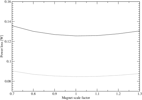
Figure 1 illustrates how much the power losses would be further reduced if research and development provided a stronger (i.e. larger) magnetic gradient. This curve shows the power deposition from radiative Bhabhas for the High Luminosity beam parameter set, as a function of magnet scale factor for the optimised NbTi 500 GeV final doublet (solid curve) and the same magnet with an extra 20% of gradient in QD0.
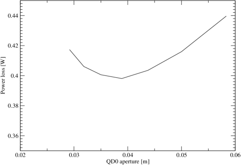
Figure 2 shows the power deposition from radiative Bhabhas for the Low Power beam parameter set, as a function of the QD0 aperture444The dependence shown here is for the baseline doublet at 500 GeV. A similarly shallow behaviour is obtained for the other cases. . The minimum in the power loss curve is reasonably shallow, which could be used to reduce the large external size of the magnet. Note that also including the charged beam losses may move this total minimum to slightly larger aperture.
Finally, the linear optics for the baseline final doublet and the optimised NbTi final doublet at 500 GeV (nominal parameters) can be seen in figures 3 and 4.
| Beam | QD0 | SD0 | QF1 | SF1 |
|---|---|---|---|---|
| Nominal | 0 W | 0 W | 0 W | 0 W |
| Nominal (dy=200nm) | 0 W | 0 W | 0 W | 0 W |
| Nomial RB | 0.40 W | 0 W | 0.01 W | 0.11 W |
| low power | 7.61 W | 0 W | 0 W | 469.76 W |
| Low power (dy=120nm) | 7.77 W | 0 W | 0 W | 188.05 W |
| Low power RB | 0.39 W | 0 W | 0.01 W | 0.10 W |
| High lum. | 91.81 W | 0 W | 0 W | 1399.82 W |
| High lum. (dy=120nm) | 88.86 W | 0 W | 5.42 W | 192.52 W |
| High lum. RB | 0.97 W | 0 W | 0.03 W | 0.25 W |
| Beam | QD0 | SD0 | QF1 | SF1 |
|---|---|---|---|---|
| Nominal | 0 W | 0 W | 0 W | 0 W |
| Nominal (dy=200nm) | 0 W | 0 W | 0 W | 0 W |
| Nomial RB | 0.05 W | 0 W | 0.13 W | 0.03 W |
| low power | 0 W | 0 W | 0 W | 0 W |
| Low power (dy=120nm) | 0 W | 0 W | 0 W | 0 W |
| Low power RB | 0.05 W | 0 W | 0.13 W | 0.03 W |
| High lum. | 0 W | 0 W | 0 W | 0 W |
| High lum. (dy=120nm) | 0 W | 0 W | 0 W | 0 W |
| High lum. RB | 0.12 W | 0 W | 0.33 W | 0.08 W |


4.2 Results for E=1 TeV
In Table 10 we show, for reference, the power losses for the baseline lattice at 1 TeV. Table 11 shows the power losses in the NbTi final doublet, optimised for 1 TeV. The low maximum gradient possible with this magnet technology means that, whilst the losses are lower than the baseline design at 1 TeV, they are still too high to avoid magnet quenching. This indicates that higher gradient magnets are required.
| Beam | QD0 | SD0 | QF1 | SF1 |
|---|---|---|---|---|
| Nominal | 0 W | 0 W | 0 W | 0 W |
| Nominal (dy=100nm) | 3.39 W | 0 W | 0 W | 0 W |
| Nominal RB | 1.02 W | 0 W | 0.01 W | 0.30 W |
| Low Power | 755.05 W | 0 W | 7.63 W | 95.37 W |
| Low Power (dy=120nm) | 897.46 W | 0 W | 20.98 W | 109.49 W |
| Low Power RB | 1.19 W | 0 W | 0.03 W | 0.34 W |
| High Lum. | 8430.59 W | 0 W | 190.17 W | 878.12 W |
| High Lum. (dy=80nm) | 14076.00 W | 0 W | 454.53 W | 1514.45 W |
| High Lum. RB | 3.60 W | 0 W | 0.11 W | 0.92 W |
| Beam | QD0 | SD0 | QF1 | SF1 |
|---|---|---|---|---|
| Nominal | 0 W | 0 W | 0 W | 0 W |
| Nominal (dy=100nm) | 0 W | 0 W | 0 W | 0 W |
| Nominal RB | 0.73 W | 0 W | 0.06 W | 0.16 W |
| Low Power | 223.94 W | 27.85 W | 5.76 W | 8.07 W |
| Low Power (dy=120nm) | 271.85 W | 6.77 W | 11.39 W | 10.66 W |
| Low Power RB | 0.15 W | 0 W | 0.39 W | 0.10 W |
| High Lum. | 3169.79 W | 703.78 W | 54.96 W | 122.87 W |
| High Lum. (dy=80nm) | 5501.98 W | 409.85 W | 352.71 W | 236.43 W |
| High Lum. RB | 2.55 W | 0 W | 0.12 W | 0.36 W |
| Beam | QD0 | SD0 | QF1 | SF1 |
|---|---|---|---|---|
| Nominal | 0 W | 0 W | 0 W | 0 W |
| Nominal (dy=100nm) | 0 W | 0 W | 0 W | 0 W |
| Nominal RB | 0.32 W | 0 W | 0.34 W | 0.10 W |
| Low Power | 20.52 W | 0 W | 28.73 W | 27.56 W |
| Low Power (dy=120nm) | 7.77 W | 0 W | 48.03 W | 40.71 W |
| Low Power RB | 0.37 W | 0 W | 0.39 W | 0.12 W |
| High Lum. | 264.42 W | 0 W | 477.77 W | 439.98 W |
| High Lum. (dy=80nm) | 473.00 W | 0 W | 1286.15 W | 670.40 W |
| High Lum. RB | 1.09 W | 0 W | 1.19 W | 0.36 W |
Finally, Table 12 shows the power losses in the Nb3Sn final doublet, optimised for 1 TeV. The higher gradients expected from using Nb3Sn superconductive material enable to significantly reduce the power deposition as compared to both the baseline and optimised NbTi final doublet designs. However, the losses are still in excess of the quenching limits of the magnets. To understand what improvement in superconducting technology would be required, we computed how much larger the pole tip field in QD0 would need to be to bring the sum of the charged beam and radiative Bhabha losses to less than 1W, for the Low Power beam parameter set. The result was that a pole tip field of 11T in a magnet with an aperture of 35mm would be needed for the Low Power beam parameter set to be accommodated in the final doublet at 1 TeV. The feasibility of such large pole tip fields on the time-scale of the 1 TeV energy upgrade of the ILC needs to be discussed with relevant superconductive magnet experts. Alternatively, beam parameters at 1 TeV may be optimised with somewhat lower beamstrahlung energy loss, including for total beam powers as low as in the present Low Power parameter set. Such sets would result in significantly easier final doublet designs.
5 CONCLUSIONS
In this note, we have described a detailed study of the power deposition in the final doublet of the ILC 2mrad crossing-angle layout, from both the disrupted charged beam and from the radiative Bhabha events. We exploited superconductive magnet technologies both currently available and expected to be developed through on-going R&D: NbTi and Nb3Sn with maximum pole tip fields of respectively 6.28 T and 8.8 T.
We find that using NbTi technology to optimise the 500 GeV baseline final doublet is adequate to obtain small enough beam power depositions in the final doublet, provided a Tungsten liner is included in the design of the vacuum chamber to spread out the showers and reduce the maximum power density at the location where most losses are concentrated. This doublet now needs to be integrated into the final focus system and extraction line. When this will be done, we will propose that it become the baseline for the 2mrad at 500GeV, with the assumption that it would have to be replaced at the time of the 1 TeV energy upgrade. In all cases, the sextupole lengths, strengths and apertures are not fully optimised. Some more work is still needed here, in view of reducing their sizes and ease their integration with the detector. It is also necessary to include the extraction line magnets in a further optimisation.
A final doublet based on NbTi technology does not, on the other hand, provide small enough beam power depositions at 1 TeV, for several of the beam parameter sets considered. Exploiting Nb3Sn superconductive technology can however improve the situation considerably, as the higher expected gradients would allow significantly lower power depositions. The optimised layout shows far superior power loss behavior than the current 1 TeV machine baseline final doublet, but is still in excess of the quenching limit for the beam parameter sets with the largest beamstrahlung energy loss. A 35mm QD0 with a pole tip field of around 11 T would be needed to a avoid quenching of this magnet, in the case of the Low Power beam parameters.
We expect further R&D in superconductive magnet technology to enable increases in maximum available pole tip field in the future, which will ease the design of the 2mrad beam crossing-angle layout. An alternative path is to constrain the optimisation of the beam parameters at 1 TeV with an upper bound on the beamstrahlung energy loss. This would also be motivated since a very large beamstrahlung energy loss is undesirable for several other reasons.
Acknowledgement
We would like to thank Andrei Seryi and Deepa Angal-Kalinin for helpful advice and assistance, Grahame Blair for useful discussions and John Carter for his assistance computing the effect of a Tungsten liner in the vacuum chamber.
References
- [1] The ILC BCD, http://www.linearcollider.org/wiki/doku.php?id=bcd:bcd_home
- [2] http://www-project.slac.stanford.edu/lc/
- [3] D. Schulte, EuroTeV memo 2005-004-1
-
[4]
Appleby et al, EuroTeV report 2006-001-01,
http://alcpg2005.colorado.edu:8080/alcpg2005/program/accelerator/WG4/aug17_nosochkov_extraction2mrad.pdf - [5] http://www-project.slac.stanford.edu/ilc/acceldev/beampar/Suggested%20ILC%20Beam%20Parameter%20Space.pdf
- [6] Bruning et al, LHC project report 785, CARE-Conf-04-005-HHH
- [7] Brett Parker, private communication
- [8] John Carter, private communication, see talk by R. Appleby, LCWS06, India, 9-13 March 2006
- [9] Lew Keller, Takashi Maruyama, private communication
- [10] A. Seryi, Unit 6 of Physics and Technology of Linear Collider Facilities, US-PAS, Santa Barbara, June 2003
- [11] http://www.cern.ch/mad
- [12] http://www-project.slac.stanford.edu/lc/local/accelphysics/codes/gp/Sramek/index.htm
- [13] http://www.slac.stanford.edu/accel/nlc/local/AccelPhysics/codes/dimad/