Toward the Stable Optical Trapping of a Droplet with Counter Laser Beams under Microgravity
Abstract
To identify the optimum conditions for the optical trapping of a droplet under microgravity, we theoretically analyzed the efficiency of trapping with counter laser beams. We found that the distance between the two foci is an important parameter for obtaining stable trapping conditions. We also performed an optical trapping experiment with counter laser beams under microgravity. The experimental results correspond well to the theoretical prediction.
, , ,
1 Introduction
Since the discovery of optical trapping in 1970 by Ashkin[1], optical tweezers have been actively applied in the fields of biology, physical chemistry, condensed matter physics and so on[2]. Recently, some reports have mentioned the advantages of such systems on the International Space Station (ISS)[3][4]. The technique of optical trapping is expected to be useful on the ISS for the manipulation of droplets on a to sub- scale, including in crystal growth by avoiding the effect of vessels. However, as far as we know, there has been no report on the optical trapping of a droplet under microgravity conditions in air.
Recently, we reported the optical levitation of a droplet under a linear increase in gravitational acceleration using a single laser[5]. To attain stable optical trapping with a single beam, it is necessary to use a lens with a high magnification. This means that the working distance, or the distance between the lens surface and the object, is rather small; on the order of a few . In view of such application on the ISS, it is important to find the stable trapping condition with a greater working distance. Toward this end, we adapted an optical system with low-converged counter laser beams for optical trapping with a long working distance.
2 Theoretical
We consider the counter laser system shown in Fig.1. In this system, the distance between the foci plays a crucial role. Although the qualitative property of such counter laser systems has been discussed in Ref.[6], the effect of the distance has not yet been discussed in detail. Here, we calculate the trapping force produced by counter lasers with the variables and (which is the radius of a spherical object).
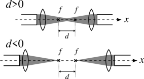
To take into account the effect of the inertia of the object, we start our discussion with a motion equation. To simplify the problem, we consider motion along the -direction as in Fig.1.
| (1) |
where is the mass of the object, is the acceleration of the object along the -direction, is the force along the optical axis induced by the converged laser, and is the other forces (including the effective acceleration force along the -direction and random force induced by air).
As we see in the latter part, the velocity of the trapped object is at most . We assume that the scale of the trapped object is at most , and the kinetic viscosity of air is around . In this condition, the Reynolds number is: and we can apply Stokes’ approximation. By calculating and , we can verify the relation ; where the radius of the trapped droplet is on the order of 10 , the experimental time resolution is , the velocity of the trapped droplet , the viscosity of air and the density of the droplet . This estimation indicates that the viscous force is large enough to locate the droplet at an equilibrium position in the optical potential. Therefore, under reasonable assumptions of the viscous limit, we discuss the stability of trapping droplets through and the effective optical potential.
is found as follows. In the case of trapping a large object(, where is the wavelength of laser), we can calculate the trapping force with the ray optics theory. Within the framework of ray optics, a TEM00 mode laser can be divided into rays, which are suffixed with , and each power of the ray is related to the beam deviation and lens size Each ray hits the surface of the droplet at a different incident angle (), repeatedly reflects and is transmitted in the droplet until the intensity of the rays decreases to the zero limit, and the momentum is given with a certain efficiency along the -axis, :
| (2) |
where : incident angle, : refractive angle, :reflection coefficient and : transmission coefficient. These parameters are obtained by considering the geometric relation between the droplet and the direction of the beam (see ref.[7]). Assuming a spherical droplet with radius whose center is located at distance from the center of the foci, we calculate the details of the reflections and transmissions for all paths of the laser beam. The total force is
| (3) |
where : trapping efficiency along the optical axis and : velocity of light. In addition, considering the distances between the foci, the total force is:
| (4) |
Under the assumption of a spherical trapped object, optical trapping exhibits geometrical symmetry and we can use a normalized unit of length. Eventually, the optical potential is expressed by two normalized parameters, and .
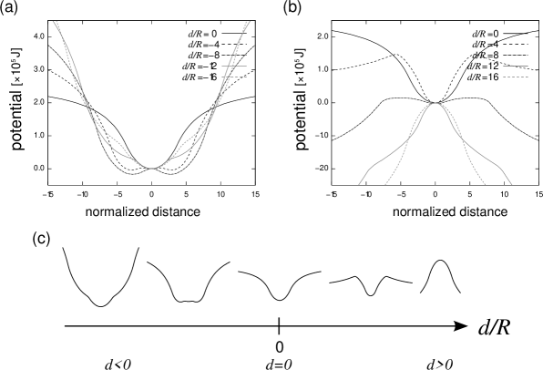
The results of the calculation for effective trapping potential are shown in Fig.2, indicating that the trapping efficiency is significantly dependent on . An optical configuration with positive is clearly preferable for optilcal trapping under microgravity. Figure 2(c) shows the change in the potential profile as a function of . As shown, not only the distance between the foci but also the radius of the droplet greatly affect the profile of the optical potential. This chart is reasonable for understanding qualitative properties: if the radius is sufficiently large, the trapped object is insensitive to the distance between the foci and the sign of become less important. In contrast, when is sufficiently small, becomes non-negligible and we must choose better settings of . Since we sought to define the optimum conditions for trapping large objects (sub-mm scale), this diagram is applicable for designing a counter laser trapping system. For example. if we can precisely adjust the positions of the foci, the setting at is advantageous for trapping the object rather than . The potentiality to trap small particles is important in the growth of protein crystals[8][9] and liquid droplets[10].
3 Experimental
Microgravity conditions were achieved by using a jet airplane(Mitsubishi MU-300, operated by Diamond Air Service Co., Aichi, Japan). In the experiment, the airplane flew along a parabolic flight profile, as shown in Fig.3. During parabolic flight, the effective gravitational acceleration in the airplane was 0.01 for about 20 s, where the gravitational acceleration on the ground .
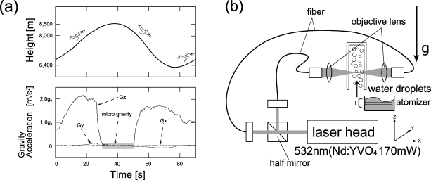
The experimental setup for the optical trapping is shown in Fig.3(b). We selected a counter laser system to press the droplets to the center of the foci.[11][12] The laser beam from a diode pumped () was split into two beams by a half mirror, transferred via optical fibers, and focused by achromatic lenses. The convergence angle of the lenses was 17 degrees, so the working distance was on the order of cm. The laser power was set to 170 mW. We arranged two different optical settings, where the positions of the laser foci are different, either is positive or negative as shown in Fig.1. The droplets were injected into a glass cell with an atomizer. The droplets, as visualized by scattering visible laser light, were monitored with a CCD camera from the y-direction in Fig.3(b). Movies were recorded at 30 frames per second. The experiments was carried out at arround 298K.
4 Results and Discussion
On the ground in air, using the same optical trapping system, the injected droplets immediately fell due to the force of gravity. However, under microgravity in air, most of the droplets didn’t fall and we could observe the motions of the droplets along the laser axes. To trace the droplets’ motion along the laser axes, we converted the movie images to a spatio-temporal diagram. Figure 4 shows the results of the optical trapping of the droplets under microgravity.
|
 |
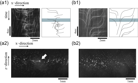
Figure 4 (a1) and (b1) are spatio-temporal diagrams which show the trajectory of the droplets. Figure 4 (a2) and (b2) are snapshots of the droplets. In these figures, the burring on the images correspond to rather fast motion of the droplets. The small white spots are droplets that have departed from the laser axes and are floating in front of or behind the camera foci. In contrast, a trapped droplet is a star-like object(white arrow), since a trapped droplet on the laser axes scatter light intensively.
Figure 4(c) shows typical profiles depicted based on the results of Fig.2(a) and (b), which are associated with the two different optical settings in Fig.4(a2) and (b2). As shown near the trapping region, the gradient force in the case of the solid arrow is much greater than that in the case of the dashed arrow(). It is clear that our theoretical study reproduces the experimental trends well.
5 Conclusion
We performed the optical trapping of a water droplet with a counter laser in air under microgravity and investigated the properties of the counter laser trapping system. We showed that the position of the laser foci strongly affected the trapping efficiency. A theoretical calculation based on ray optics reproduced the experimental trend. The present results may contribute to the design of a manipulation system on the International Space Station (ISS), including experiments on protein crystal growth and a container-less micro-reactor.
6 Acknowledgement
The authors thank Mr. S. Watanabe, Mr. Y. Sumino, and N. Matsuda for their helpful suggestions and Ms. Hayata and Messrs. Fujii, Kawakatsu, and Takahashi for their technical assistance. This research was supported in part by a Grant-in Aid from the Ministry of Education, Science, Sports and Culture of Japan, the Grant-in-Aid for the 21st Century COE Center for Diversity and Universality in Physics from the Ministry of Education, Culture, Sports, Science and Technology (MEXT) of Japan, and Ground-based Research Announcement for Space Utilization promoted by the Japan Space Forum.
References
- [1] A. Ashkin, Acceleration and trapping of particles by radiation pressure, Phys. Rev. Lett. 24 (1970) 156.
- [2] D. G. Grier, A revolution in optical manipulation, Nature 424 (2003) 810.
- [3] J. Panda, C. R. Gomez, Setting up a rayleigh scattering based flow measuring system in a large nozzle testing facility, NASA/TM (2002) 211985.
- [4] S. Y. Wrbanek, K. E. Weiland, Optical levitation of micro-scale particles in air, NASA/TM (2004) 212889.
- [5] M. I. Kohira, A. Isomura, N. Magome, S. Mukai, K. Yoshikawa, Optical levitation of a droplet under a linear increase in gravitational acceleration, Chem. Phys. Lett. 414 (2005) 389.
- [6] G. Roosen, A theoretical and experimental study of the stable equilibrium positions of spheres levitated by two horizontal laser beams, Opt. Comm. 21 (1977) 189.
- [7] A. Ashkin, Forces of a single-beam gradient laser trap on a dielectric sphere in the ray optics regime, Biophys. J. 61 (1992) 569.
- [8] R. Giegé, J. Drenth, A. Ducruix, A. McPherson, W. Saenger, Study of the aerodynamic trap for containerless laser materials processing in microgravity, Prog. Cryst. Growth Charact. Mater. 30 (1995) 237.
- [9] Y. Hosokawa, S. Matsumura, H. Masuhara, K. Ikeda, A. Shimo-oka, H. Mori, Laser trapping and patterning of protein microcrystals: Toward highly integrated protein microarrays, J. Appl. Phys. 96 (2004) 2945.
- [10] N. Magome, M. I. Kohira, E. Hayata, S. Mukai, K. Yoshikawa, Optical trapping of a growing water droplet in air, J. Phys. Chem. B 107 (2003) 3988.
- [11] G. Roosen, C. Imbert, Optical levitation by means of two horizontal laser beams: A theoretical and experimental study, Phys. Lett. 59A (1976) 6.
- [12] T. Cizmar, V. Garcés-Chávez, K. Dholakia, P. Zemánek, Optical conveyor belt for ddelivery of submicron objects, Appl. Phys. Lett. 86 (2005) 17401.