Circular conversion dichroism in planar chiral metamaterials
Abstract
We report the first experiential observation and theoretical analysis of the new phenomenon of planar chiral circular conversion dichroism, which in some aspects resembles the Faraday effect in magnetized media, but does not require the presence of a magnetic field for its observation. It results from the interaction of an electromagnetic wave with a planar chiral structure patterned on the sub-wavelength scale, and manifests itself in asymmetric transmission of circularly polarized waves in the opposite directions through the structure and elliptically polarized eigenstates. The new effect is radically different from conventional gyrotropy of three-dimensional chiral media.
Since Hetch and Barron Hetch and Barron (1994) and Arnaut and Davis Arnaut and Davis (1995) first introduced planar chiral structures to electromagnetic research they have become the subject of intense theoretical Prosvirnin and Zheludev (2005); Bedeaux et al. (2004) and experimental investigations with respect to the polarization properties of scattered fields Papakostas et al. (2003); Schwanecke et al. (2003); Takahashi et al. (2005). It was understood by many that planar chirality is essentially different in symmetry from three-dimensional chirality. Whereas in three-dimensional chiral structures the sense of perceived rotation remains unchanged for opposing directions of observation (think, for example, of a helix observed along its axis), planar chiral structures possess a sense of twist that is reversed when they are observed from opposite sides of the plane to which the structure belongs. Consequently, if planar chiral structures were to exhibit a polarization effect (due to this twist) for light incident normal to the plane, the sense of the effect would be reversed for light propagating in opposite directions. Such behavior has never been observed before, but if proven would be of profound benefit to the development of a new class of microwave and optical devices.
In this paper we report such a polarization sensitive effect. It is a previously unknown fundamental phenomenon of electromagnetism that asymmetric materials can generate behaviors that in some ways resemble the famous non-reciprocity of the Faraday effect, which emerges when a wave propagates through a magnetized medium. However, the phenomenon reported here does not require the presence of a magnetic field and results from an electromagnetic wave’s transmission through a chiral planar structure patterned on the sub-wavelength scale. Both in the Faraday effect and in that produced by planar chirality, the transmission and retardation of a circularly polarized wave are different in opposite directions. In both cases the polarization eigenstates, i.e. polarization states conserved on propagation, are elliptical (circular).

There are also essential differences between the two phenomena. The asymmetry of the Faraday effect with respect to propagation in opposite directions applies to the transmission and retardation of the incident circularly polarized wave itself. The planar chirality effect leads to the (partial) conversion of the incident wave into one of opposite handedness, and it is the efficiency of this conversion that is asymmetric for the opposite directions of propagation (see Fig.1). The eigenstates of an anisotropic Faraday medium are two elliptically polarized waves of opposite handedness. The eigenstates of a planar chiral medium are two elliptical polarizations of the same handedness. The newly observed effect of planar chirality is also radically different from conventional gyrotropy in three-dimensional chiral media, such as the sugar solution which is complectly symmetric with respect to the inversion of the direction of propagation. The later property of conventional gyrotropy results from the fact that the sense of helicity of a spiral (or any three-dimensional chiral object for this matter) does not depend on the direction at which it is observed. The propagation asymmetry observed in planar chiral media is nevertheless compatible with the general notion of reciprocity as defined by the Lorentz Lemma. Moreover, the asymmetric effect in planar chiral structures is inherently linked to losses in the structure. This will be explained in more detail below.
If a medium is described by a complex transmission matrix for the field amplitudes of the incident and transmitted circularly polarized waves, then , where the indices and correspond to the transmitted and incident polarization states, which could be either right (RCP, ) or left circular polarizations (LCP, ). The matrix for an isotropic magnetized Faraday medium and matrix for isotropic three-dimensional chiral medium are diagonal matrices. In the Faraday medium the transmission matrices for opposing directions of propagation (denoted by arrows), i.e. and , are related by the permutation of their diagonal elements, while in the three-dimensional chiral medium the transmission matrices for opposing directions of propagation, i.e. and , are identical. In these terms the transmission matrix for a planar chiral anisotropic medium is a non-Hermitian matrix with equal diagonal elements . The transmission matrices for opposing directions of propagation will be mutually transposed: = . For a given direction of propagation the equality of the diagonal elements implies that losses and retardation are identical for RCP and LCP waves passing through the structure. However, since , switching between RCP to LCP incident waves leads to a change in the intensity and phase of the corresponding LCP and RCP converted circular components.
The new propagation phenomenon described by the matrix has been observed in a chiral ‘fish-scale’ planar structure. This is a chiral version of a new type of electromagnetic meta-material, the non-chiral form of which was recently investigated for its frequency selective properties and ‘magnetic wall’ behavior Fedotov et al. (available at arXiv.org: cond-mat/0504761). The chiral ‘fish-scale’ is a 2-dimensional continuous pattern of tilted meanders existing in two enantiomeric (mirror) forms interconverted by reflection across a line in the plane of the structure (see Fig.2). On the basis of both intuitive perception and strict
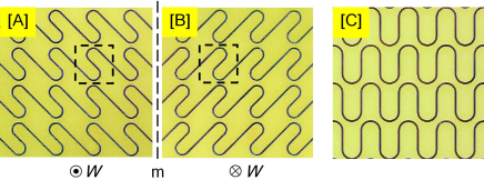
mathematical definition Potts et al. (2004), the left-tilted fish-scale A shows an overall anti-clockwise twist, while the right-tilted fish-scale B twists clockwise. An axial ‘twist’ vector , governed by the cork-screw law, may be associated with each of the enantiomers.
In the experiments reported here we used a metallic fish-scale structure, with a square translation cell, etched from a copper film on a thick dielectric PCB material substrate (see Fig. 1). The width of the strips was . The overall size of the samples was approximately . We studied the reflection and transmission of this structure in the spectral range, performing measurements in an anechoic chamber using a vector network analyzer (Agilent, model E8364B). The structure does not diffract electromagnetic radiation at frequencies lower than so a single-wave regime was achieved in the experiments. We investigated transmission through the two enantiomeric forms of the chiral fish-scale structure at normal incidence. The handedness of the pattern depends on whether it is observed from one side of the screen or the another. In this paper the handedness will be defined as seen by the incident electromagnetic wave and the structure will be referred to as being ‘clockwise’ if the vector W is antiparallel to the direction of the incident wave. All parameters for the incident and transmitted waves will be defined in a right-handed cartesian coordinate frame where the axis is directed perpendicular to the plane of the structure along the direction of the incident wave, while the and axes are directed along and perpendicular to the meander lines respectively.
Measuring the circular polarization transmission matrix
directly requires circularly polarized emitters and receivers.
Although circular polarization antennae exist, they are only capable
of producing high purity circular polarization in a narrow spectral
range and are therefore not suitable for broadband measurements.
Instead, we used high-quality broadband linearly polarized and
log-periodic antennas (Schwarzbeck M. E. model STLP 9148) and
measured the complex transmission matrix for linearly polarized
fields. The complex circular polarization transmission matrix was
then calculated as follows:
In the following we also use an intensity transmission and conversion matrix =. The matrix for fish-scale structures A and B, where transmission is measured for waves entering the structure from the side of the metal pattern, will be denoted and respectively. Measurements were also conducted for waves entering the structures from the opposite side, i.e. through the dielectric layer first. The corresponding transmission matrices are and .
The transmission properties of the fish-scale structure were also rigorously modelled using the method of moments described in Prosvirnin et al. (2002.). This widely used computational approach is based on a vectorial integral equation for the surface current induced by the electromagnetic wave on the metal strips of the structure, which are assumed to form an infinitely thin perfectly conducting patterned with topography identical to the structures used in the experiment (see Fig. 2). This analysis takes into account electromagnetic losses in the dielectric substrate supporting the metal structure, which are introduced through the imaginary part of the complex relative permittivity of the substrate material . The results of these calculations show remarkable agreement with those of the experiments. They are presented in figures 3 and 4 as continuous lines alongside the experimental points.
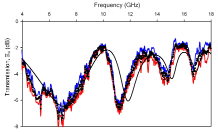
The data presented in Fig. 3 illustrates that within experiential accuracy, the diagonal elements of matrix are equal across the whole spectral range of interest. Moreover, the diagonal elements are the same for the two enantiomeric fish-scale structures A and B and for propagation in both directions. In Fig. 3 we present the squared modulus of the diagonal elements, but their arguments linked to the phase retardation of the corresponding circular components of the transmitted waves are also equal within experiential accuracy. The fact that the diagonal elements of the transmission matrix are independent of the propagation direction and the chirality of the sample is fully consistent with the outcome of calculations based on the method of moments. This indicates that the structure does not manifest a polarization effect of the same symmetry as conventional optical activity or the optical Faraday effect in bulk media. However, it shows an intriguing new assymetric polarization conversion effect.
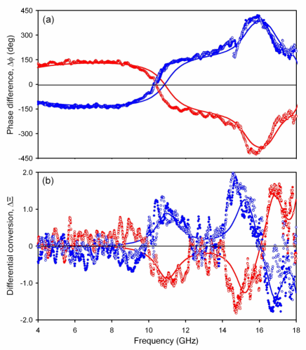
The data presented in Fig. 4 illustrates polarization conversion and the asymmetric properties of the chiral fish-scale structures. Fig. 4a shows the phase difference between converted polarization components resulting from excitation with circularly polarized waves of opposite handedness, measured as . Here one can see that the differential phase delays for the two enantomeric forms of the structure have opposite signs, i.e. . On the other hand, for a given structure the differential phase delay observed in the forward direction is the same as the delay for its enantiomer observed in the opposite direction, i.e. . Similar symmetries are observed for the normalized difference in the intensities of the converted waves, measured as . Once again and . This indicates that the perceived sense of rotation of the planar chiral structure (which depends on whether the structure is observed from one side or another) controls the sing of the effect. In other words it matters if the wave vector of the incident wave is parallel or anti-parallel to the vector of structure’s twist (see Fig. 1). This is in sharp contrast with conventional gyrotropy in three-dimensional chiral media where observable effect do not depend on the direction of propagation.
It should be noted that our raw experiential data for the cartesian transmission matrix, and the results of computational analysis, show that in all cases , and , . The last two of these equalities constitute the requirement imposed on transmission through a planar chiral structure by the Lorentz Lemma Kong (2005). In terms of circular polarizations the Lemma may be re-written as an equality = , which holds within experimental and computational tolerance as illustrated in Fig. 4. Thus, the effect presented here does not mount any challenge to the validity of the reciprocity Lemma. The somewhat surprising compatibility of this asymmetric effect with the Lorentz Lemma is easily explained by the fact that the asymmetry observed here results from the asymmetry of polarization conversion for circular polarizations in the opposite directions of propagation, i.e. , while the Lorentz Lemma only requires that . In comparison, for the Faraday effect and the Lorentz Lemma does not hold, nor indeed is it supposed to in the presence of a magnetic field.
The origin of the assymetric interaction may be traced to the
structure of the transmission matrix . It may be presented
as a sum , where
and is a symmetric matrix and is an anti-symmetric matrix. Here is the wave
vector of the incident wave. The antisymmetric part is proportional
to a pseudo-scalar combination that changes its sign on
reversal of the direction of propagation. It gives rise to the
difference between and
and is therefore responsible for the
direction-dependent transmission. Essentially, the anti-symmetric
part is also proportional to , i.e. it may only exist in
anisotropic patterns of low symmetry (if the structure possesses a
4-fold symmetry axis, ). Moreover, it is only in
dissipative systems that cannot be eliminated by the choice
of an appropriate coordinate system. In other words, transmission
asymmetry is only possible in anisotropic dissipative planar chiral
structures.
The origins of and are completely different. results from the structures’ anisotropy. Its value depends on how enatiomeric samples are mutually oriented in the experiment. More specifically it depends on the orientation of the meander’s direction of both enantiomers with respect to the line of mirror symmetry inter-converting them. does not lead to any asymmetrical effects that can be detected in the intensity of propagating waves. In contrast, results in an observable intensity effect. The effect is astonishing: the planar chiral structure is more transparent to a circularly polarized wave from one side than from another. For instance for an incident RCP wave the total transmitted intensity in the forward direction is given by , while in the opposite direction it is given by . In spite of the fact that , polarization conversion is asymmetric, i.e. , leading to a difference in the total transmitted intensities. No such dependence on the direction of propagation would be seen in a lossless chiral structure or an anisotropic non-chiral planar or bulk material of any description (indeed, no was detected for the anisotropic non-chiral fish-scale structure C). Therefore this phenomenon is somewhat analogous to the magnetic circular dichroism effect (MCD) and may be called planar chiral circular conversion dichroism (PCD). Our calculations show that it is inherently linked to losses and increases in proportion to the imaginary part of the complex relative permittivity of the substrate material. Lossless planar chiral metamaterial shall not display asymmetric transmission for a circularly polarized wave. As we already mentioned above, this asymmetric effect is also forbidden in any planar structure containing a 4-fold axis of rotation and is therefore irrelevant to the recent observation of the polarization rotation in four-fold gammadion arrays Kuwata-Gonokami et al. (2005).
Our theoretical analysis shows that in lossy anisotropic planar chiral structures the asymmetry of total transmission is accompanied by similar asymmetries in reflection and absorption. Nevertheless, the total energy is always conserved. The spectral dispersions of transmission, reflection and absorbtion asymmetries are, in general, different and can therefore take zero values at certain frequencies. For instance, at frequency absorption is the same for both directions of propagation. Here the asymmetric transmission is due solely to the asymmetric reflection. At transmission asymmetry vanishes, but the asymmetry of reflection exists and is due to the asymmetry of absorption.
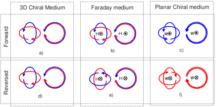
Knowledge of the complex transmission matrix enables the calculation of the polarization eigenstates of the system, i.e. the polarization states that are not affected by transmission through the planar structure (see Fig 5). In analog to the anisotropy of bulk media, the eigenstates of an anisotropic non-chiral planar structure are two mutually perpendicular linear polarizations. In a loss-less chiral structure they are also linear. However, the eigenstates become elliptically polarized in lossy planar chiral structures. In contrast to the Faraday effect, or conventional three-dimensional chirality in bulk media for that matter, where the eigenstates are a pair of counter-rotating elliptical states, the eigenstates of a lossy planar chiral structure are two co-rotating elliptical polarizations as illustrated in Fig. 5. These eigenstates only differ in the azimuths of their main axes (they are orthogonal). As in the case of the Faraday effect (but in contrast to gyrotropy in conventional three-dimensional chiral media), the sense of rotation of the elliptically polarized eigenstates is reversed for the opposite direction of propagation through a planar chiral structure. It is interesting to note here that if a planar chiral structure is somehow continuously transformed so as to retain its geometrical chirality but to reduce its anisotropy, the eigenstates will tend towards a degenerate single circularly polarized eigenstate. This eigenstate has only asymptotic meaning because in isotropic planar chiral media the polarization conversion effect vanishes.
We derived the ellipticity of the eigenstates from the eigenvectors of the experimental transmission matrix and also calculated corresponding theoretical values for the matrix obtained by the method of moments. In both cases the frequency dispersion of the ellipticity strongly resembles the dispersion of with the maximum ellipticity angle reaching 35 deg. As expected, the polarization eigenstate ellipticities have opposite signs for counter-propagating directions and for enantiomeric samples. Here the ellipticity of the polarization state is defined in standard fashion as , where and are components of the the Stokes Parameter of the polarization state.
In conclusion, circular conversion dichroism in a planar chiral structure is a unique, previously unknown effect, which results from the chirality and anisotropy of the structure and is inherently linked to dissipation in the substrate. An attempt to describe it in terms of an effective medium approximation, and in particular to attribute it to the standard classification scheme of local and non-local reciprocal and non-reciprocal polarization phenomena in homogeniouse media Smolenskii et al. (1975); Birrs and Shrubsall (1967), fails and is not appropriate. Therefore this phenomenon is perhaps more closely related to but not the same as the theoretically predicted phenomena of non-reciprocal transmission through the interface between local and non-local media Svirko and Zheludev (1998), and circular differential reflectivity of planar chiral interface Bedeaux et al. (2004). We expect that the asymmetry of transmission through an appropriately scaled sub-wavelength chiral planar structure could be seen in optical experiments.
Acknowledgements.
The authors would like to acknowledge the financial support of the Engineering and Physical Sciences Research Council, UK and the EU Network of Excellence ‘Metamorphose’.References
- Hetch and Barron (1994) L. Hetch and L. D. Barron, Chem. Phys. Lett 225, 525 (1994).
- Arnaut and Davis (1995) L. R. Arnaut and L. E. Davis, in Proceedings of the International Conference on Electromagnetics in Advnaced Applications (Nexus Media, Swanley, UK, 1995), pp. 381–388.
- Prosvirnin and Zheludev (2005) S. L. Prosvirnin and N. I. Zheludev, Phys. Rev. E 71, 037603 (2005).
- Bedeaux et al. (2004) D. Bedeaux, M. A. Osipov, and J. Vlieger, J. Opt. Soc. Am. A 21, 2431 (2004).
- Papakostas et al. (2003) A. Papakostas, A. Potts, D. M. Bagnall, S. I. Prosvirnin, H. J. Coles, and N. I. Zheludev, Phys. Rev. Lett. 90, 107404 (2003).
- Schwanecke et al. (2003) A. S. Schwanecke, A. Krasavin, D. M. Bagnall, A. Potts, A. V. Zayats, and N. I. Zheludev, Phys. Rev. Lett. 91, 247404 (2003).
- Takahashi et al. (2005) S. Takahashi, A. Potts, D. Bagnall, N. I. Zheludev, and A. V. Zayats, Opt. Comm. 255, 91 (2005).
- Fedotov et al. (available at arXiv.org: cond-mat/0504761) V. A. Fedotov, P. L. Mladyonov, S. L. Prosvirnin, and N. I. Zheludev, Phys. Rev. E., in press (available at arXiv.org: cond-mat/0504761).
- Potts et al. (2004) A. Potts, D. M. Bagnall, and N. I. Zheludev, J. Opt. A 6, 193 (2004).
- Prosvirnin et al. (2002.) S. Prosvirnin, S. Tretyakov, and P. Mladyonov, J. Electromagn. Waves Applic. 16, 421 (2002.).
- Kong (2005) J. A. Kong, Electromagnetic wave theory (EMW Publishing, Cambridge, Massachusetts, USA, 2005).
- Kuwata-Gonokami et al. (2005) M. Kuwata-Gonokami, N. Saito, Y. Ino, M. Kauranen, K. Jefimovs, T. Vallius, J. Turunen, and Y. Svirko, Phys. Rev. Lett. 95, 227401 (2005).
- Smolenskii et al. (1975) G. A. Smolenskii, R. V. Pisarev, and I. G. Sinii, Usp. Fiz. Nauk 116, 231 (1975).
- Birrs and Shrubsall (1967) R. R. Birrs and R. G. Shrubsall, Phil. Mag. 15, 687 (1967).
- Svirko and Zheludev (1998) Y. P. Svirko and N. I. Zheludev, Polarization of Light in Nonlinear Optics (Wiley, Chichester, 1998).