Nanowire metamaterials with extreme optical anisotropy
Abstract
We study perspectives of nanowire metamaterials for negative-refraction waveguides, high-performance polarizers, and polarization-sensitive biosensors. We demonstrate that the behavior of these composites is strongly influenced by the concentration, distribution, and geometry of the nanowires, derive an analytical description of electromagnetism in anisotropic nanowire-based metamaterials, and explore the limitations of our approach via three-dimensional numerical simulations. Finally, we illustrate the developed approach on the examples of nanowire-based high energy-density waveguides and non-magnetic negative index imaging systems with far-field resolution of one-sixth of vacuum wavelength.
The anisotropy of effective dielectric permittivity is widely used in optical, infrared (IR), THz and GHz sensing, spectroscopy, and microscopyanisot4 ; belov ; shvetsPRL ; shultzTHzpolarizer . Strongly anisotropic optical materials can be utilized in non-magnetic, non-resonant optical media with negative index of refraction, and have the potential to perform subdiffraction imaging and to compress the radiation to subwavelength areasenghetaWG ; belov ; podolskiyPRB ; govyadinovFunnels . The performance of these polarization-sensitive applications can be related to the relative difference of the dielectric constant along the different directions. In the majority of natural anisotropic crystals this parameter is below palik . While it may be sufficient for some applications, a number of exciting phenomena ranging from high-performance polarization controlshultzTHzpolarizer to subwavelength light guidinggovyadinovFunnels ; enghetaWG ; belov to planar imagingpodolskiyPRB require different components of a permittivity tensor to be of different signs.
In this Letter we study the perspectives of using nanowire composites as meta-materials with extreme optical anisotropy. We demonstrate that even stretching/compression of the nanowire structures may dramatically affect the electromagnetic properties of these systems and change the sign of components of the permittivity tensor. We present an analytical description of wave propagation in anisotropic nanowire composites – Generalized Maxwell-Garnett approach (GMG), and verify our technique via three-dimensional (3D) numerical simulations. Finally, we illustrate our approach on the examples of several nanowire-based systems for light compression below the diffraction limit and negative refraction-imaging with far-field resolution of (with being free-space wavelength).
The use of metallic wire mesh as anisotropic low-frequency plasma has been proposed inpendryWires and experimentally realized for normal light incidence inshultzTHzpolarizer ; shultzNIM . However, the applicability of these nanowire-based materials for any non-trivial geometry involving oblique light incidence or wave-guiding is still considered to be questionable due to strong nonlocal interactionsshvetsWires , that may potentially result in positive components of the permittivity tensor. Furthermore, the majority of existing effective-medium theories (EMTs)shvetsWires ; MG ; stroud ; miltonBook are limited to the optical response of nanowires that are isotropically distributed in the host material. The predicted response of these systems is almost independent of nanowire distribution and is described by a single parameter – nanowire concentration. These existing techniques are therefore not applicable for practical composites where the geometry is anisotropic due to fabrication process or as a result of a controlled mechanical deformationpark . Understanding the optical behavior of nanowire structures beyond one-parameter EMT is the main purpose of this Letter.
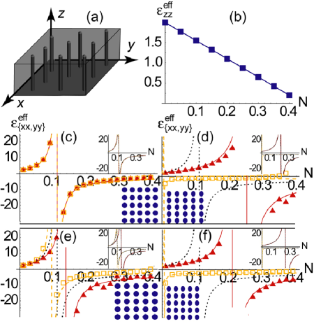
The geometry of the nanowire composites considered in this work is shown in Fig.1. The nanowires with permittivity are embedded into a host material with permittivity . The nanowires are aligned along the direction of Cartesian coordinate system. We assume that the nanowires have elliptic crossections with the semi-axes and directed along and coordinate axes respectively. We further assume that the homogeneous nanowire composite may be compressed or stretched, leading to the anisotropic distribution of individual nanowires. The typical separations between the nanowires and directions are denoted by and footnoteLXLY . In this work we focus on the case of “homogeneous metamaterial”, when the inhomogeneity scale is smaller than the wavelength () and nanowire concentration is small so that the lattice feedback effects can be treated using perturbative techniques as described below [for the case of additional requirement , with being skin depth in wires, must be fulfilled]. Under these conditions, Maxwell equations have free-space-like solutions that can be represented as a series of plane electromagnetic waves propagating inside a material with some effective dielectric permittivitylandauECM :
| (1) |
The angular brackets in Eq.(1) denote the average over microscopically large (multi-wire), macroscopically small (subwavelength) region of the space, with Greek indices corresponding to Cartesian components, and assumed summation over the repeated indices. If both and are isotropic, the normal axes of the tensor of effective dielectric permittivity will coincide with the coordinate axes. Thus, in the selected geometry the permittivity tensor becomes diagonal: , with being the Kronecker delta function.
We now derive the expressions for the components of the effective permittivity and . Using the continuity of the component, Eq.(1) yields:
| (2) |
Note that similar to what was found in Refs.shvetsWires ; MG ; stroud ; miltonBook , the single parameter that determines the component of the permittivity in the effective medium regime is nanowire concentration .
To find () components of the we use the Maxwell-Garnett (MG) techniqueMG ; stroud ; miltonBook . This approach assumes so that the local field in the composite is homogeneous across a nanowire. The fields and are then averaged over a typical nanowire cell, and Eq.(1) is used to extract the effective permittivity of a material. Naturally, average fields will have two contributions: one coming from the fields inside nanowires , and the second one coming from the fields between nanowires . The derivation of an EMT is therefore equivalent to understanding the relationship between and the external field acting on the system . Conventional MG approach assumes that stroud ; MG , which is true only for the case of isotropic nanowire distributions. The crucial point of this work is that both and are strongly influenced by the nanowire distribution (given by the parameters ), and nanowire shape (described by ) along with nanowire concentration .
We now derive the analytical expressions for and . The typical excitation field acting on a nanowire in the sample will contain the major contribution from external field and the feedback field scattered by all other nanowires in the structure , resulting in the effective excitation . For rectangular, triangular, and other highly-symmetrical lattices, as well as for a wide-class of random nanowire micro-arrangements, the feedback tensor becomes diagonaljacksonBook , with the effective field acting on a nanowire being footnoteIntCoef .
Using the dimensionless function with summation going over all pairs of , except coordinate origin, the summation of dipole fields over rectangular lattice shown in Fig.1(a) yields footnoteInfSum
| (3) | |||||
where we introduced the lattice distortion vector , and polarization term , with being the depolarization factorslandauECM ; miltonBook . Note that the feedback parameter vanishes only for isotropic nanowire distribution , corresponding to the well-known MG resultMG ; stroud ; miltonBook ; pendryWires ; shvetsWires .
This inter-wire interaction changes the “microscopic” field acting on the individual nanowires, and thus it directly affects both (homogeneous) field inside the nanowire landauECM ,
| (4) |
and the average field in-between the nanowires . Direct calculation of the average dipolelandauECM of a given inclusion over the typical meta-material cell yields:
| (5) |
with and shape vector .
Combining Eqs.(1,4,5) we arrive to the following expression for the in-plane components of permittivity in GMG approach:
| (6) |
To verify the accuracy of the developed GMG technique, we generate a set of nanowire composites with given values of , , , , and , excite each composite with a homogeneous field, and use the commercial finite-element partial differential equations solver, COMSOL Multiphysics 3.2COMSOL to solve Maxwell equations, find the microscopic filed distribution, and calculate the average values of , and over the volume of a composite, yielding . In the simulations we used both random and periodic nanowire composites; the number of nanowires was sufficient () to eliminate the dependence of on the sample size [finite-sample-size artifacts]. Fig.1 shows the excellent agreement between GMG approach presented in this work and numerical solution of Maxwell equations in quasistatic limit for concentrations and deformations . Our simulations indicate that the quasi-static material properties are fully described by average parameters . This particular property of the effective-medium composites indicates high tolerance of anisotropic metamaterials to possible fabrication defects.
As expected, the field distribution across the nanowire structure and are strongly affected by , as well as and . Thus, even anisotropy in inclusion shape or distribution may result in change of sign of dielectric permittivity. Such an effect opens the possibility to create optical materials with widely controlled opto-mechanical properties, potentially leading to new classes of polarizers, beam shapers, polarization-sensitive sensing and fluorescence studies, as well as for a wide class of ultra-compact waveguidesenghetaWG ; govyadinovFunnels since the material properties may be tuned between and . Some of these applications are described below.
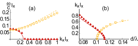
As it has been noted for GHz systems inshvetsWires , the components of may be strongly affected by the spatial dispersion. To clarify these effects we used COMSOL package to identify the eigen waves propagating in -direction through a planar waveguide with a composite core consisting of a rectangular array of Ag nanowires in Si host, extending from to (see Fig.1a), bounded by perfectly conducting walls (see podolskiyPRB for the detailed explanation of the effects of waveguide walls and material absorption on the mode propagation). In Fig.2(a) we show the agreement of the results of numerical solutions of 3D wave equations with the EMT dynamics of TE and TM modes propagating in a waveguide with homogeneous anisotropic core, described by
| (7) |
with and being the modal wavevector, speed of light in the vacuum, and waveguide thickness, respectively. Note that this system does not support TEM modespodolskiyPRB .
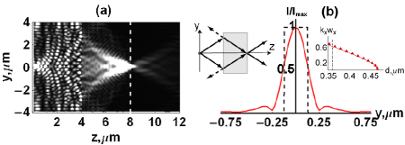
Fig.2(b) illustrates one of the applications of nanowire-based optical composites, high-energy-density waveguide – a subwavelength structure supporting propagating volume modes. It is important to point out that in contrast to uniaxial media, anisotropic () nanowire composites can simultaneously support both -TE and -TM waves (). Moreover, the in-plane anisotropy (induced, for example, by deformation) can be used as a controlling mechanism in nanoscale nanowire-based pulse-management devices.
It is clearly seen that the propagation of these modes is adequately described by GMG technique when . As expected, the material properties in EMT regime are independent of nanowire micro-arrangements (type of crystalline lattice), while the exact point of EMT breakup () depends on local geometry and is maximized for almost-rectangular lattices [assumed in derivation of Eq.(3)]. Note that the real requirement for EMT applicability, , is different from the commonly used criterion . Indeed, our simulations show that the spatial dispersion leads to cut-off of the modes with , similar to what has been predicted for GHz wire systems shvetsWires and nanolayer-based photonic funnelsgovyadinovFunnels .
Another application of nanowire structures, non-magnetic negative-index materials podolskiyPRB is illustrated in Fig.3. It is seen that the nanowire materials may be used to achieve sub-diffraction () far-field resolution in the planar-lens geometry.
In conclusion, we have developed the effective-medium theory (GMG) that adequately describes the optical properties of nanowire composites with anisotropic crossections and arrangements. Limitations of the proposed approach have been studied via numerical modeling. We demonstrated that the nanowire composites can be used to achieve extreme anisotropy at optical and IR frequencies, with controlled effective permittivity ranging from to to – thus leading to practical implementations of high-energy-density waveguidesgovyadinovFunnels ; enghetaWG , novel polarization-sensitive detectors, and recently proposed non-magnetic negative index systemspodolskiyPRB . Finally, we note that the technique presented here can be readily applied to dielectric, plasmonic, and polar-wire composites at optical, IR, and THz frequencies, and can be further extended to the cases of non-aligned inclusions, anisotropic and , and 3D composites similar to what have been done for isotropic-arrangement cases inmiltonBook ; stroud .
This research is partially supported by GRF (OSU), Petroleum Research Fund (ACS), and PRISM (Princeton).
References
- (1) P. Krecmer, A.M. Moulin, R.J. Stephenson, T. Rayment, M.E. Welland, S.R. Elliott, Science, 277 1799 (1997); W.T. Doyle, and I. S. Jacobs, J. Appl. Phys. 71, 3926, (1992); D. Schurig, D.R. Smith, Appl. Phys. Lett. 82 2215 (2003)
- (2) P. Belov, C. Simovski, Phys. Rev. E72 036618 (2005)
- (3) G. Shvets, Y.A. Urzhumov, Phys. Rev. Lett. 93, 243902 (2004);
- (4) D. Wu, N. Fang, C. Sun, X. Zhang, W.J. Padilla, D.N. Basov, D.R. Smith, S. Schultz, Appl. Phys. Lett. 83 201 (2003).
- (5) A. Alu and N. Engheta, IEEE Trans. Micr. Th. and Tech. 52 p.199 (2004)
- (6) A.A.Govyadinov and V.A. Podolskiy, Phys. Rev. B73, 155108 (2006); A.A. Govyadinov, V.A. Podolskiy, arXiv:physics/0605036
- (7) V.A. Podolskiy and E.E. Narimanov, Phys. Rev. B71, 201101(R) (2005); R. Wangberg, J. Elser, E.E. Narimanov and V.A. Podolskiy J. Opt. Soc. Am. B23, 498 (2006)
- (8) E. Palik (ed.) The handbook of optical constants of solids, Academic Press (London, UK 1997)
- (9) J.B. Pendry, A.J. Holden, W.J. Stewart, and I. Youngs, Phys. Rev. Lett. 76, 4773 (1996); A.K.Sarychev, R.C. McPhedan, V.M. Shalaev, Phys. Rev. B62, 8531 (2000)
- (10) D.R. Smith, W.J. Padilla, D.C. Vier, S.C. Nemat-Nasser, S. Shultz, Phys. Rev. Lett. 84, 4184 (2000);
- (11) A.Pokrovsky, A.Efros, Phys. Rev. Lett. 89, 093901 (2002); G. Shvets, A.K. Sarychev, V.M. Shalaev, Proc. SPIE 5218, 156 (2003); P.Belov, R.Marques, S.Maslovski, I.Nefedov, M.Silveirinha, C.Simovski, S.Tretyakov, Phys. Rev. B67, 113103 (2003); A.L. Pokrovsky, A.L. Efros, Phys. Rev. B65, 045110(2002)
- (12) J.C.M. Garnett, Philos. Trans. R. Soc. London, Ser. B 203, 385 (1904)
- (13) A. Khizhniak, Zh.Tech.Phys., 27, 2027 (1957); O. Levy, D. Stroud, Phys. Rev. B56, 8035 (1997); A. Lakhtakia, B. Michel, W.S Weiglhofer, J. Phys. D: Appl. Phys. 30, 230 (1997); A.Kirchiner, K.Busch, C.M. Soukoulis, Phys. Rev. B57, 277 (1998); A.N. Lagarkov, A.K. Sarychev, Phys. Rev. B53, 6318 (1996)
- (14) G.W. Milton, The theory of composites, Cambridge U. Press, (Cambridge, UK, 2002)
- (15) Q.Wu, W.Park, Appl. Phys. Lett. 85, 4845 (2004)
- (16) Mathematically, the average area of the unit cell in random anisotropic composite is related to the average separation between neighboring elements along two orthogonal directions and through the metric tensor : . The tensor becomes diagonal in “eigen” axes , used as primary directions throughout the manuscript.
- (17) L.D. Landau, E.M. Lifshitz, and L.P. Pitaevskii Course of theor. phys. Vol.8, 2-nd ed., Reed publishing Ltd (Oxford UK 1984)
- (18) J.D. Jackson, Classical Electrodyanmics, J.Wiley and Sons, Inc. (New York, NY, 1999)
- (19) The role of parameters used in this work is similar to that of interaction coefficients introduced for Lorentz model incollinBook . These two techniques provide identical results for isotropic (in plane) composites, while the Eq.(6) tends to be more robust than Lorentz model when
- (20) Collin ”Field Theory of Guided Waves”, 2-nd edition, Willey-Interscience (New York, NY, 1991)
- (21) Note that while in the limit , the expression remains finite for with .
- (22) For details see COMSOL Multiphysics User’s Guide and Electromagnetis Module User’s Guide; (c) COMSOL AB (1994-2005); www.comsol.com