Reflectionless evanescent-wave amplification by two dielectric planar waveguides
Mankei Tsang and Demetri Psaltis
Department of Electrical Engineering, California Institute of Technology, Pasadena, California 91125
Abstract
Utilizing the underlying physics of evanescent-wave amplification by a negative-refractive-index slab, it is shown that evanescent waves with specific spatial frequencies can also be amplified without any reflection simply by two dielectric planar waveguides. The simple configuration allows one to take advantage of the high resolution limit of a high-refractive-index material without contact with the object.
OCIS codes: 110.2990, 230.7390
Conventional optical imaging systems cannot resolve features smaller than the optical wavelength, because the high-spatial-frequency modes that describe the subwavelength features are evanescent waves, which exponentially decay away from the object and do not propagate to the far field. Observing the evanescent waves is therefore one of the most important yet formidable challenges in the field of optics, with important applications in optical lithography, data storage, and microscopy. Near-field scanning optical microscopy can detect the evanescent waves [1], but it requires scanning, which may not be desirable for many applications. A groundbreaking proposal by Pendry suggests that evanescent waves can be amplified without any reflection in a negative-refractive-index slab [2], causing significant interest as well as controversy [3] in the mechanism of evanescent-wave amplification (EWA). On the practical side, the fabrication of a negative-refractive-index material for optical frequencies is a challenging task, as it requires both negative permittivity and negative permeability, the latter of which does not naturally occur in materials, and methods of implementing an effective negative refractive index [4, 5, 6] often introduce significant loss detrimental to the EWA process. As proposed by Pendry [2] and experimentally demonstrated by Fang et al. [7], a negative permittivity in a metal slab can also amplify evanescent waves to some extent, but the thickness of the slab is limited by the electrostatic approximation as well as loss. A simpler EWA scheme that utilizes less lossy materials would thus be desirable.
Along this direction, Luo et al. propose that a photonic crystal slab can be used to amplify evanescent waves [8], since evanescent waves with specific spatial frequencies can be coupled into the bound states of the photonic crystal slab, and the build-up of the bound states produces an enhanced evanescent tail on the other side of the slab. Apart from the difficulty in fabricating a three-dimensional photonic crystal for two-dimensional imaging, the kind of EWA achieved by a photonic crystal slab is not ideal, because the build-up of the bound states also creates enhanced reflected evanescent waves, causing multiple evanescent wave reflections between the object and the photonic crystal. On the other hand, in order to obtain information about the output evanescent waves on the image plane, energy must be extracted, and the only way for the detector to “tell” the imaging system to give up energy is via a reflected evanescent wave. In other words, detection of an evanescent wave always creates a reflected evanescent wave, so there exist multiple reflections between an imaging system and the detector as well. Since the magnitudes of evanescent wave transmission and reflection coefficients can be larger than 1 or even infinite, multiple evanescent wave reflections can be very significant and should not be ignored in the design of near-field imaging systems. An ideal near-field imaging system should hence have unit transmission as well as zero reflection, as if the imaging system is not there and the object directly touches the image plane. This ideal behavior also allows multiple imaging systems to be cascaded and a longer distance between the object and the detector.
In this Letter, the underlying physics of reflectionless evanescent-wave amplification (REWA) by the use of a negative-refractive-index slab is explained, and, using this knowledge, it is shown that evanescent waves with specific spatial frequencies can be amplified without reflection simply by two dielectric planar waveguides. Since loss in a dielectric can be orders-of-magnitude lower than metals or metamaterials, our proposed scheme is the simplest way of experimentally demonstrating the intriguing phenomenon of REWA and offers simple alternatives to the use of left-handed materials, surface plasmons, or photonic crystals for near-field imaging applications.
One of the most poorly understood aspects of Pendry’s proposal is that at the interface of an material and an material, the transmission and reflection coefficients are theoretically infinite [2]. Mathematically this indicates the presence of an unstable pole on the imaginary axis in the complex transverse-spatial-frequency () plane, and physically the transmitted and reflected evanescent optical fields must therefore increase linearly along a semi-infinite interface. This is hardly surprising if one recalls the well-known fact that infinite scattering coefficients correspond to bound-state solutions, so the incoming evanescent waves are simply resonantly-coupled into the waveguide modes of the interface. The most peculiar aspect of Pendry’s interface is that the scattering coefficients are always infinite, meaning that bound-state solutions exist for all . This is not true for other waveguides, including photonic crystals [8], which have discrete bound states with different discrete ’s. In particular, for ideal surface plasmons, only one bound state exists.
First, consider a dielectric slab with thickness and refractive index in the plane. Suppose that an evanescent s-polarized wave with an electric field exponentially decaying along the positive axis, given by , impinges on the slab, where is assumed to have subwavelength resolution, so , is determined by the dispersion relation, given by , , and is the refractive index of the surroundings. Considering the first interface between and only, the reflected wave is , and the transmitted wave inside the slab is . is the same on both sides of the interface, and is given by the dispersion relation , where . is hereafter assumed to be real for waveguide modes to exist. This restricts to be bounded by the wave numbers in the two media,
| (1) |
The transmission and reflection coefficients across the first interface are given by and respectively. Likewise, the scattering coefficients across the second interface are and . To obtain the total transmission, , across the slab, multiple scattering events must be summed,
| (2) | ||||
| (3) |
The total reflection coefficient can be obtained similarly,
| (4) |
Waveguide modes correspond to those with evanescent tails exponentially decaying away from the waveguide. In other words, the total transmitted evanescent wave and the total reflected evanescent wave for the waveguide modes can exist by themselves without any incoming wave , or, mathematically speaking, and are infinity. This happens when
| (5) |
which simply states that the accumulated phase in a round trip inside the waveguide must be multiples of . As both and depend on , Eq. (5) is an eigenvalue equation of for the TE modes of the single waveguide. A simple dielectric slab can hence achieve EWA due to the waveguide mode coupling resonances, similar to a photonic crystal [8]. If only subwavelength features are concerned and all-angle negative refraction [9] is not needed, a complicated structure such as photonic crystal is not necessary. However, just like a photonic crystal, the reflection coefficient of a slab waveguide is also infinite, causing potential problems with multiple reflections.
In Pendry’s proposal, both interfaces of a negative-refractive-index slab need to be considered for ideal REWA. The two interfaces can be considered as two waveguides, and the total transmission of the slab exponentially increases with respect to the thickness of the slab, or the distance between the two waveguides, when the single-interface scattering coefficients are infinite. This suggests that REWA may also exist for other kinds of double-waveguide structures, when the resonant coupling condition of the single waveguide is reached.
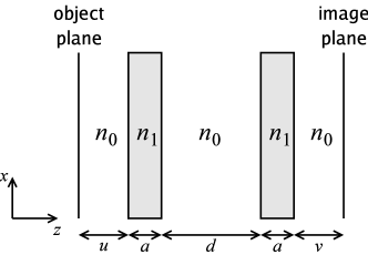
Now let us go back to the dielectric slab waveguide example and add another identical waveguide a distance away from the first, as depicted in Fig. 1. The total transmission coefficient for this double-waveguide structure is
| (6) |
When coincides with one of the single-waveguide bound-state eigenvalues determined by Eq. (5), the total transmission becomes
| (7) |
which increases exponentially with respect to . The total reflection coefficient of the double-waveguide structure is likewise given by , and in the limit of being a bound-state eigenvalue of a single waveguide,
| (8) |
Hence, an evanescent wave can propagate with perfect transmission and zero reflection in the setup depicted in Fig. 1, thereby achieving REWA, if and the resonant single-waveguide coupling condition is reached. Identical results can also be derived for p-polarized waves and TM modes. REWA should be quite general for any kind of symmetric and identical waveguides, so two photonic crystal slabs may be used to achieve all-angle negative refraction [9] and REWA simultaneously.
For imaging applications, it is important to stress that the double-waveguide device only beats the resolution limit of the cladding layer with refractive index , but not the resolution limit of the core layer with refractive index . This is because the bound-state eigenvalues of are bounded by wave numbers of the two media, as shown by Eq. (1). That said, a waveguide can be designed such that the maximum of a waveguide mode is close to the wave number of the core medium, so the proposed device can still take advantage of the high resolution limit offered by a high-refractive-index material without contact with the object. This can be advantageous for many applications because many solids have higher refractive indices than fluids but it is not very practical to fill the whole imaging system with solids as in oil immersion microscopy. Furthermore, for biomedical imaging applications, it is not always possible to place the high-refractive-index material directly in touch with the object plane, as the contact may damage the biological sample, or one may desire to put the object plane inside a semi-transparent object, such as a cell.
Promising high-refractive-index material candidates include diamond, which can have a refractive index as high as 2.7, [10] and transparent down to a wavelength of about 230 nm [11], and coherently-prepared atoms (confined in, say, a dielectric box) with a resonantly-enhanced refractive index [12], which can theoretically reach the order of one hundred [13] and a proof-of-concept experiment of which has already been demonstrated [14].
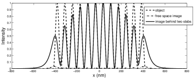
An outstanding problem of using any waveguide, except negative-refractive-index slabs, for EWA is that ideal enhancement only occurs for single-waveguide modes, which are discrete and band-limited for each . For instance, the discrete ’s of the TE modes in a symmetric slab waveguide are determined by Eq. (5) and band-limited by Eq. (1). As a result, an object with frequency components that lie outside the waveguiding band or do not coincide with the bound states cannot be perfectly reproduced. Waveguide slabs are therefore particularly suited to periodic image transmission. As a simple example, consider an approximately periodic pattern in a dielectric medium with an index for to represent the source, and at the object plane a dielectric-air interface is present at to create evanescent waves for via total internal reflection. Assume that nm, nm, nm, , , and nm, for a total transmission distance of nm, and another dielectric medium with an index is present behind the image plane to convert the evanescent waves back to propagating waves to represent the detector. The image intensities in free space and behind two dielectric slabs, respectively, are plotted in Fig. 2. The image enhancement due to the presence of the dielectric slabs is clearly evident. One may also use a multimode waveguide or a broadband light source to increase the amount of transmitted spatial frequencies for more complex objects.
This work was sponsored by the Defense Advanced Research Projects Agency (DARPA) Center for Optofluidic Integration.
References
- [1] E. Betzig and J. K. Trautman, Science 257, 189 (1992).
- [2] J. B. Pendry, Phys. Rev. Lett. 85, 3966 (2000).
- [3] See, for example, N. Garcia and M. Nieto-Vesperinas, Phys. Rev. Lett. 88, 207403 (2002).
- [4] S. Zhang, W. Fan, B. K. Minhas, A. Frauenglass, K. J. Malloy, and S. R. J. Brueck, Phys. Rev. Lett. 94, 037402 (2005).
- [5] S. Zhang, W. Fan, N. C. Panoiu, K. J. Malloy, R. M. Osgood, and S. R. J. Brueck, Phys. Rev. Lett. 95, 137404 (2005).
- [6] V. M. Shalaev, W. Cai, U. K. Chettiar, H.-K. Yuan, A. K. Sarychev, V. P. Drachev, and A. V. Kildishev, Opt. Lett. 30, 3356 (2005).
- [7] N. Fang, H. Lee, C. Sun, and X. Zhang, Science 308, 534 (2005).
- [8] C. Luo, S. G. Johnson, J. D. Joannopoulos, and J. B. Pendry, Phys. Rev. B 68, 045115 (2003).
- [9] C. Luo, S. G. Johnson, J. D. Joannopoulos, and J. B. Pendry, Phys. Rev. B 65, 201104 (2002).
- [10] D. F. Edwards and E. Ochoa, J. Opt. Soc. Am. 71, 607 (1981), and references therein.
- [11] C. D. Clark, P. J. Dean, and P. V. Harris, Proc. Roy. Soc. A 277, 312 (1964).
- [12] M. O. Scully, Phys. Rev. Lett. 67, 1855 (1991).
- [13] M. Fleischhauer, C. H. Keitel, M. O. Scully, C. Su, B. T. Ulrich, and S.-Y. Zhu, Phys. Rev. A 46, 1468 (1992).
- [14] A. S. Zibrov, M. D. Lukin, L. Hollberg, D. E. Nikonov, M. O. Scully, H. G. Robinson, and V. L. Velichansky, Phys. Rev. Lett. 76, 3935 (1996).
Erratum
In a previous Letter [1], we assert in Eq. (8) that the reflection coefficient of a double-waveguide structure, , goes to zero in the limit of single-waveguide resonance, Eq. (5) in Ref. 1. A more careful derivation shows that this is not the case,
| (9) | |||
| (10) | |||
| (11) |
Although the expression in Eq. (10) approaches zero, approaches infinity, and an application of L’Hopital’s rule shows that is given by Eq. (11), not zero. That said, the possibility of a vanishing , thereby achieving reflectionless evanescent-wave amplification, still exists. This condition is obtained by assuming that goes to zero but neglecting the case in which ,
| (12) | ||||
| (13) |
the total transmission coefficient, , becomes
| (14) | ||||
| (15) |
which, coincidentally, is the same as Eq. (7) in Ref. 1. Hence, reflectionless evanescent-wave amplification can still be achieved, provided that Eq. (13) in this Erratum, which now depends on , the distance between the two waveguides, is satisfied.
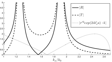
Using the same example as in Ref. 1, where nm, nm, , , and nm, Fig. 3 plots , , and versus . It is clear that is finite when is zero, but there exists a different at which vanishes, while at this has the desired value predicted by Eq. (15). The double-peak shape of and is due to the non-degenerate waveguide modes of the double-waveguide structure, which would create the undesirable multiple evanescent-wave reflections as described in Ref. 1.
The numerical example depicted by Fig. 2 in Ref. 1, calculated using a multiple-scattering analysis, is still correct and unaffected by the above issue.
In conclusion, when single-waveguide resonance is reached, the double-waveguide structure is capable of evanescent-wave amplification, but not without reflection. Reflectionless evanescent-wave amplification can still be achieved by two dielectric planar waveguides, provided that Eq. (13) in this Erratum, not Eq. (5) in Ref. 1, is satisfied.
References
- [1] M. Tsang and D. Psaltis, Opt. Lett. 31, 2741 (2006).