2005 ALCPG & ILC Workshops - Snowmass,
U.S.A.
Physics Options at the ILC.
GG6111GG6
Snowmass home page:
http://alcpg2005.colorado.edu:8080/alcpg2005/program/accelerator/GG6/agenda.
Participants: T. Omori, convener (KEK), B. Parker, convener (BNL),
P. Bambade (LAL), G. Gronberg (LLNL), C. Heusch (UCSC), S. Kanemura
(Osaka), Yu. Kolomensky (LBNL), K. Kubo (KEK), D. J. Miller (UCL),
K. Mönig (DESY), S. Mtingwa (N.Carolina U.), D. Scott (Daresbury),
A. Seryi (SLAC), A. Wolski (LBNL). Summary at Snowmass2005
Abstract
At Snowmass2005 the Global Group 6 (Physics Options) considered the requirements and configurational issues related to possible alternatives to the baseline collisions, including , , , GigaZ and fixed target experiments, and identified the potential performance parameters.
I PHOTON COLLIDER
I.1 Introduction
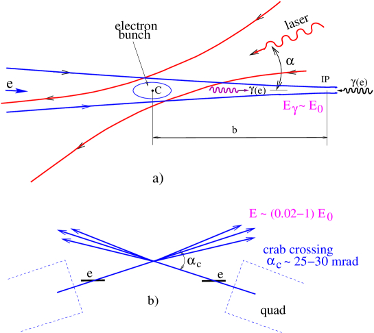
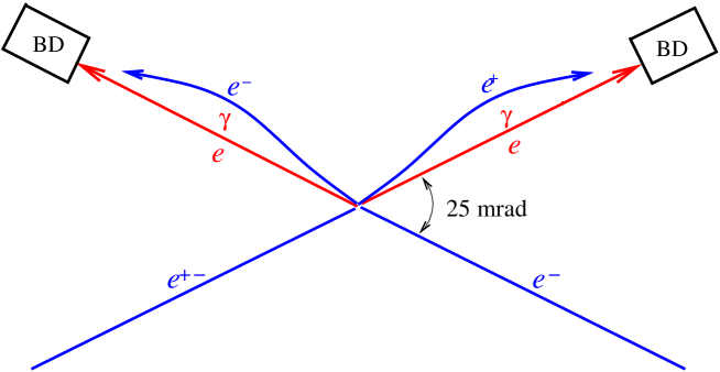
At the photon collider, and collisions are obtained by ”conversion” of electrons into high-energy photons using Compton scattering of laser light at the distance 1–2 mm from the interaction point (IP), Fig. 1. For the energy GeV, the optimum wavelength (determined by the threshold for pair creation at the conversion region) is about 1 m, which coincides with that of the most powerful lasers available today. The maximum energy of photons is about 80% of the electron beam energy, so the maximum invariant mass of the system is about 80% of the c.m.s. beam energy; for collisions it is 90%. Lower invariant masses are obtained by decreasing the electron beam energy. For example, to study the Higgs boson of 120 GeV mass, one needs =200 GeV. The most comprehensive description of the photon collider available at present that is the TESLA TDR TESLATDR ; almost all considerations done for TESLA are valid for the ILC as well.
At the nominal ILC parameters, the expected luminosity in the high-energy peak of the luminosity spectrum Telnov_snow05_1 . However, the luminosity at the ILC is not restricted by collision effects and can be increased by a factor of 2–3 by reducing emittances in damping rings (which is not easy but possible), reaching (0.3–0.5) . Typical cross sections of many interesting processes in collisions (charged pairs, Higgs, etc) are higher than those in collisions by about one order of magnitude, so the number of events in collisions will be larger than in even for the nominal beam parameters foreseen for collisions.
The physics program of the photon collider is very rich and complements in an essential way the physics in collisions, independently of the physics scenario. In , collisions, compared to ,
-
•
the energy is smaller only by 10–20%;
-
•
the number of interesting events is similar or even larger;
-
•
access to higher particle masses (H,A in , SUSY in );
-
•
higher precision for some phenomena;
-
•
different types of reactions;
-
•
highly polarized photons.
In summary, the physics reach of a , collider is not worse than that of a collider it is based on. The only advantage of collisions is the narrower luminosity spectrum, a feature that is of rather limited use. It is very important to note that the photon collider can be added to the linear collider nearly for free (the laser system, modification of the IP and one of detector add less than 3–4% of the ILC cost). The decrease of the running time by 25–30% is a neglegible price to pay for the opportunity to look for new phenomena in other types of collisions.
I.2 Special requirements for the ILC
The photon collider presents several special requirements that should be taken into account in the baseline ILC design:
-
•
For the removal of disrupted beams, the crab-crossing angle at one of the interaction regions should be about 25 mrad (the exact number depends on the quad design); the quad fringe field should be small in the region of the outgoing low-energy beam;
-
•
The luminosity is nearly proportional to the geometric luminosity, so the product of the horizontal and vertical emittances should be as small as possible (this translates into requirements on the damping rings and beam transport lines);
-
•
The final-focus system should provide beam spot sizes at the interaction point as small as possible (compared to the case, the horizontal -function should be smaller by one order of magnitude);
-
•
The very wide disrupted beams should be transported to the beam dumps with acceptable losses. The beam dump should be able to withstand absorption of very narrow photon beam after the Compton scattering;
-
•
The detector design should allow easy replacement of elements in the forward region (100 mrad);
-
•
Space for the laser and laser beam lines has to be reserved.
I.3 Crossing angle
.
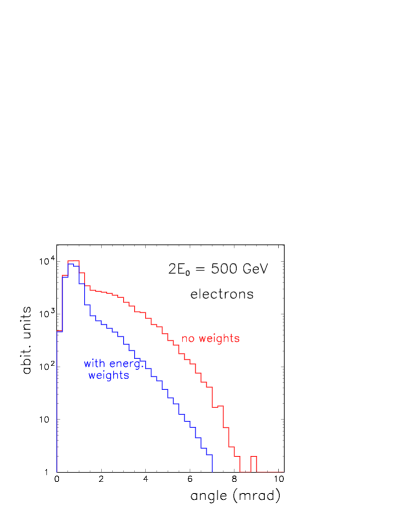
After passing the conversion and collision points, the electrons have energy from about 5 GeV up to and the horizontal disruption angle up to about 10 mrad, see Fig.2 (due to limited statistics in simulation, about macroparticles, the maximum angles should be multiplied by a factor of 1.2 TESLATDR ).
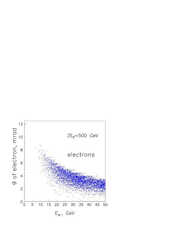
Above this angle, the total energy of particles is less than that in the secondary irremovable background.
For removal of these disrupted beams one needs the crab-crossing angle to be larger than the disruption angle plus the angular size of the final quad, see Fig. 1. Thare is an additional requirement: the field outside the quad (in the region of the disrupted beam) should be small in order to add a small deflection angle for low-energy particles.
Possible quad designs for the photon collider were considered at Snowmass2005 by B. Parker. In his initial design, the field outside the superconducting quad was shielded by an active superconducting screen (winding) around the disrupted beam Parker . This solution is possible but rather difficult, and compensation is not sufficient. At the workshop, B. Parker produced another, much more attractive quad design, which gives a minimum crossing angle, see Fig. 3. In short, the quad consists of two quads of different radi s, one inside another, with opposite field directions. In this design the gradient on the axis is reduced only by 15%, the field outside the quad is practically zero, so no additional shielding is required.
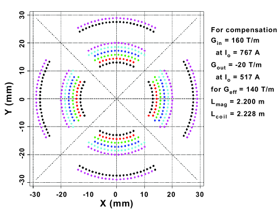
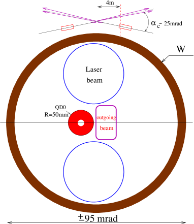
The radius of the quad, the cryostat taken into account, is cm. For the horizontal disruption angle of 11 mrad (with about 20% margin) the minimum crab-crossing angle is 23–27 mrad for the distance of the quad from the IP 4.5–3.5 m, respectively. Obtaining the final numbers requires some additional checks, but roughly it is 25 mrad. RElative positions of the quad, the outgoing electron beam and the laser beam at the distance 4 m from the IP is shown in Fig. 4
Several important remarks concerning the crossing angle:
-
•
In considering the required crab-crossing angle we assumed that the bunch length mm. This gives mrad. At present, the bunch length mm is also considered for collisions. The disruption angle for low energy particles is proportional to and depends very weakly on transverse beam sizes. This means that for mm the disruption angle is about 14–15 mrad and the required crab-crossing angle 30 mrad. So, shorting of the bunch length is not desirable for the photon collider.
-
•
In evaluating the disruption angles, we assume that the thickness of the laser “target” is equal to one scattering length for electrons with initial energy (65% of electrons scatters). Further increase of the conversion probability leads to lowering the electron energies due to multiple scattering and, correspondingly, to increasing disruption angles.
-
•
We assumed that the laser wavelength is m for all ILC energies. Due to pair creation in the conversion region, at the energy 700–800 GeV it is desirable that a longer laser wavelength be used. The disruption angles in this case will be smaller.
-
•
For low-energy operation, say GeV, one can consider the possibility of using a shorter laser wavelength (doubled of triplet frequencies) in order to increase the energy of backscattered photons and improve the shape of the spectrum. However, this would lead to increasing disruption angles. Fixing mrad, we close the possibility of shortening the laser wavelength. For physics this is acceptable, lower parameters even have some advantages for the Higgs study.
-
•
Due to the detector field beams collide at a non-zero vertical collision angle which is several times larger than , Fig.5. This angle can be removed by dipole correction winding in quads telnov_lcws05_1113 . Such a correction shifts the IP vertically by about 300 m, which is acceptable.
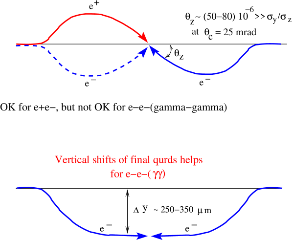
Figure 5: Trajectories of electron (positron) in the presence of the solenoid field and crab-crossing angle. At the lower figure, the collision angle is made zero using shifted quads. -
•
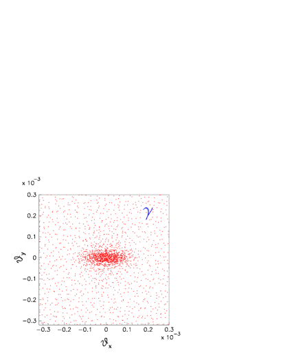
The solenoid field gives an additional deflection angle to the disrupted beam. The vertical deflection for lowest-energy particles (5 GeV) by the solenoid field is about 5 mrad, which adds to the 10–12 mrad acquired during the beam-beam collisions, so the total vertical angle is about 17 mrad. The solenoid field also leads to some horizontal displacement of the disrupted beam (due to vertical motion of particles) but it is smaller than the vertical shift of the beam. Figure 6 shows the influence of the detector field on the disrupted beam. These figures correspond to head-on collisions at the photon collider with beam energies and 500 GeV. For beams with an initial mutual shift at the IP, the central core is shifted due to the instability of collisions but the maximum angles are practically do not change and decrease for large beams shifts.
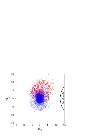
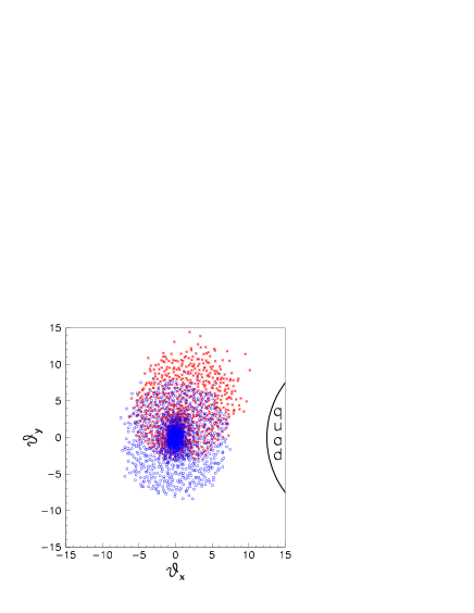
Figure 6: The shift of the disrupted beam due to the detector field. Blue (square)points: only beam-beam deflection, red (stars) points: the detector field of 4T is added. A crab-crossing angle of 25 mrad and GeV are assumed. Positions of particles are taken at the distance of 4 m from the IP, at the place where they pass the first quad. Left figure: GeV, right: GeV. The total number of macroparticles in the beam (several collisions) is about 150000. Taking into account the tails, which can cause backgrounds, the “effective” beam sizes are larger by about 20%. .
-
•
Synchrotron radiation (SR) in the detector field leads to an increase of the vertical beam size. This effect was considered in Refs. telnov_lcws05_1113 ; Telnov_snow05_1 . Detector fields used in simulations are shown in Fig. 7. Results of the simulation are presented in Table 1; the statistical accuracy is about 0.5%. We see that at the crossing angle of 25 mrad the decrease of the luminosity due to the SR is 5, 1.5 and 2 % for LDC, SiD and GLD detectors, respectively. It is possible that possibly that by proper shaping of the field in the LDC the effect can be reduced further.

collisions
| (mrad) | 0 | 20 | 25 | 30 | 35 | 40 |
|---|---|---|---|---|---|---|
| LDC(TESLA) | 1. | 0.98 | 0.95 | 0.88 | 0.83 | 0.76 |
| SID | 1. | 0.995 | 0.985 | 0.98 | 0.95 | 0.91 |
| GLD | 1. | 0.995 | 0.98 | 0.97 | 0.94 | 0.925 |
collisions
| (mrad) | 0 | 20 | 25 | 30 | 35 | 40 |
|---|---|---|---|---|---|---|
| LDC(TESLA) | 1 | 0.99 | 0.96 | 0.925 | 0.86 | 0.79 |
| SID | 1 | 0.99 | 0.975 | 0.955 | 0.91 | 0.86 |
| GLD | 1 | 0.995 | 0.985 | 0.98 | 0.97 | 0.93 |
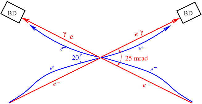
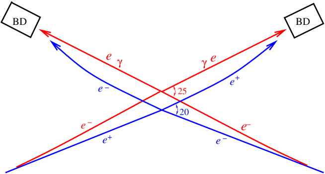
So, the crab-crossing angle needed for the photon collider is about 25 mrad, which is, in principle, compatible with . For experiments, a smaller angle is preferable, so the angles 2, 14, 20 mrad are considered. Additional considerations important for the IR design choice are the following: a) it is desirable to have the same beam dump for and modes (for the same IR), b) the beam line from the detector to the beam dump for should be curved in order to reduce background from the beam dump to the detector. Three possible configurations are shown in Fig. 8:
-
1.
In the first scheme, the crossing angle is 25 mrad both for and . Only the pathways to the beam dumps are different for and .
-
2.
In the second configuration, the crossing angle is mrad for and mrad (or even somewhat less) for . The detector and beam dump are in the same place for all modes of collisions, but the beamlines upstream of the detector (the final focus system) are at different places.
-
3.
In the third scheme, the crossing angle is mrad for and mrad (or even somewhat less) for . Transition from to operation needs the displacement of the detector and a shift of the final-focus system.
The first scheme is the easiest and needs no displacements, but the crossing angle may be somewhat larger than necessary for . The schemes 2 and 3 allow angles smaller than 25 mrad for operation. Though the third scheme needs the displacement of the detector of about (1–3) m (depends on the length of the straight chromatic correction section at the end of the final focus system; here it is assumed to be equal to about 500 m Raimondi ), it looks more attractive than the second scheme because it needs smaller total bending angles of beamlines upstream of the detector and therefore requires a smaller bending length (which is determined by the emittance dilution; for the fixed dilution of the normalize emitance ). The curved beamline to beam dump is also easier in the third scheme due to smaller total bending angle.
So, the third scheme can be recommended for the baseline configuration and needs optimization by the beam delivery working group (WG4). It seems OK for 25 mrad for and 20 mrad for . The decrease of the crossing angle down to 14 mrad is more problematic, transition from 14 to 25 mrad, certainly, requires more longitudinal and transverse space.
At the moment WG4 plans to bend the beams to the interaction points at the distance about 2000 m from the IP. This length includes also the collimation system. It makes a problem even for transition from 2025 mrad because too wide tunnel is needed. Though it is not clear for me why the 2.5 mrad bend can not be done after the collimation system at the distance about 500 m from the IP (as it was assumed above).
I.4 The luminosity
The luminosity for ILC energies is determined by the geometric luminosity of electron beams TEL_ph99 ; TEL_NIM_2001 ; TESLATDR . As has already been mentioned in the Introduction, for the nominal ILC beam parameters the expected luminosity in the high-energy peak of the luminosity spectrum . However, there is hope to increase it by a factor of 2–3. There is a general rule: .
So, one needs the smallest beam emittances and beta-functions at the IP, approaching the bunch length. Compared to the case, where the minimum transverse beam sizes are determined by beamstrahlung and beam instability, the photon collider needs a smaller product of horizontal and vertical emittances and smaller horizontal beta-function. However, there are some problems.
The existing final-focus scheme has chromo-geometric aberrations that limit the effective horizontal beta-function at about 5 mm (for the nominal horizontal emittance), Fig. 9 Seryi_snow_gg6 . For a horizontal emittance four times lower, the minimum is 2.2 mm, which increases the luminosity by a factor of 3. So, lower horizontal emittance is very desirable for two reasons.
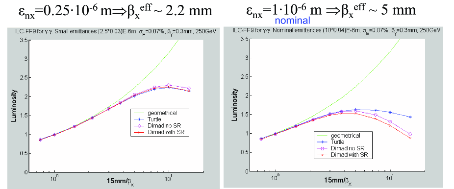
Present minimum emittances in damping rings originate from requirements for collisions, but not from physics limitations in the damping rings (DR). If we reduce the horizontal emittance by a factor of 2 and the vertical emittance by 30%, can be reduced from 5 to 3.7 mm which results in an increase of the luminosity by a factor of 2. A decrease of the horizontal emittance by a factor of 4 and by 30% the vertical one allows an increase of the luminosity by a factor of 3.5! In this case, the high-energy luminosity will reach almost 60% of luminosity, and the number of events will be greater by about a factor of 5. This certainly is a very good goal.
From A. Wolski’s talk at Snowmass Wolski_gg6 it follows that, in principle, such a decrease of emittances in DR is possible by adding wigglers in order to reduce the damping time and thus to suppress intra-beam scattering. It is necessary to study these possibilities in detail. Clearly, such a reduction of emittances will increase the DR cost, but by how much? Such a reduction of emittances would be useful for as well, but for it means a considerable increase of the luminosity (which is time and money).
I.5 Beam dump
The photon collider needs a special beam dump, very different from . There are two main differences:
-
•
Disrupted beams at the photon collider is an equal mixture of electrons and photons (and some admixture of positrons);
-
•
Disrupted beams at the photon collider are very wide (see Fig. 10), and need exit pipes with a large diameter.
-
•
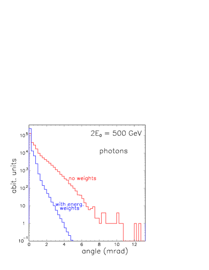
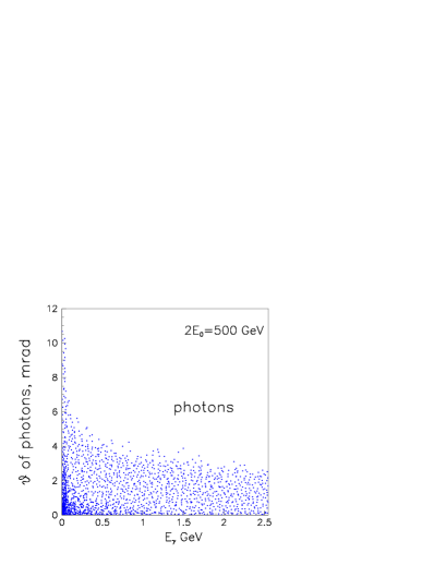
On the other hand, the photon beam after the Compton scattering is very narrow. At the distance of 250 m from the IP, the r.m.s. transverse size of the photon beam is mm2, see (see Fig. 11), with the power of about 10 MW. It cannot be dumped directly in a solid or liquid material.
There is an idea of such a beam dump and corresponding simulations Telnov-lcws04 , but the next step required a more careful study. The idea is the following. The water beam dump is situated at the distance about 250 m from IP, Fig. 12.
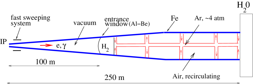
The electron beam can be swept by the fast magnets (as in the TESLA TDR) and its density at the beam dump will be acceptable. In order to spread the photon beam we suggest to put a gas target, for example Ar at atm, somewhere between the distance of 120 and 250 m: photons would produce showers, the beam diameter would increase and the density at the beam dump would become acceptable. In order to decrease the neutron flux in the detector one can add a volume with a gas hydrogen gas just before the Ar target, which would reduce the flux of backward-scattered neutrons at the IP at least by one order of magnitude. The corresponding numbers can be found in Ref. Telnov-lcws04 .
In order to reduce the diameter of the beamline between the beam dump and the IP, it is desirable to focus somewhat the disrupted electron (positron) beam just after the exit from the detector (this issue has not been considered yet). The angular distribution of beamstrahlung photons is similar to that of beamstrahlung electrons that produced these photons. However, the energy of beamstrahlung photons produced by rather low-energy large-angle electrons is only a small fraction of their energy, so the effective (energy-weighted) angular distribution of photons is narrower than that for electrons. According to Fig. 10 (right), for photons the clear angle mrad will be sufficient, which is 75 cm at the distance of 250 m.
The Ar target should have the diameter of no more than 10 cm (a shower of such diameter does not present a problem). The rest of the volume of the exit pipe with a diameter of about 1.5 m can be filled with air at 1 atm (or vacuum). Such measures are necessary in order to avoid unnecessary scattering of low-energy electrons traveling at large distances from the axis and thus to reduce the energy losses and activation of materials (water, air) in the unshielded area (it is difficult to shield a 100 m tube).
I.6 Laser system
The required laser parameters:
-
•
Wavelength m (good for GeV);
-
•
Time structure m, 3000 bunches/train;
-
•
Flash energy J (about one scattering length for GeV);
-
•
Pulse length ps.
The most attractive scheme for a photon collider with the TESLA/ILC pulse structure is storage and recirculation of a very powerful laser bunch in an external optical cavity TEL_ph99 ; TEL_NIM_2001 ; Will2001 ; TESLATDR ; Klemz2005 . This can reduce the required laser power by a factor of 100 (the quality factor of the cavity).
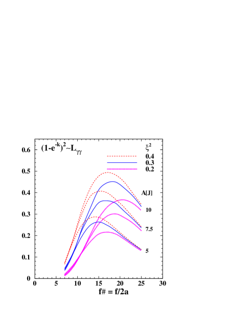
Dependence of the luminosity on the flash energy and (flat-top laser beam) for several values of the parameter (which characterizes multi-photon effects in Compton scattering, is acceptable TESLATDR ) is presented in Fig. 13 Telnov_snow05_1 . This simulation is based on the formula for the field distribution near the laser focus for flat-top laser beams. It was assumed that mrad and the angle between the horizontal plain and the edge of the laser beam is 17 mrad (the space required for disrupted beams and quads, see Fig. 4). At the optimum, , or the angular size of the laser system is about mrad. If the focusing mirror is situated outside the detector at the distance of 15 m from the IP, it should have a diameter of about 1 m. All other mirrors in the ring cavity can have smaller diameters, about 20 cm is sufficient from the damage point of view (diffraction losses require an additional check).
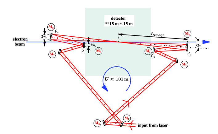
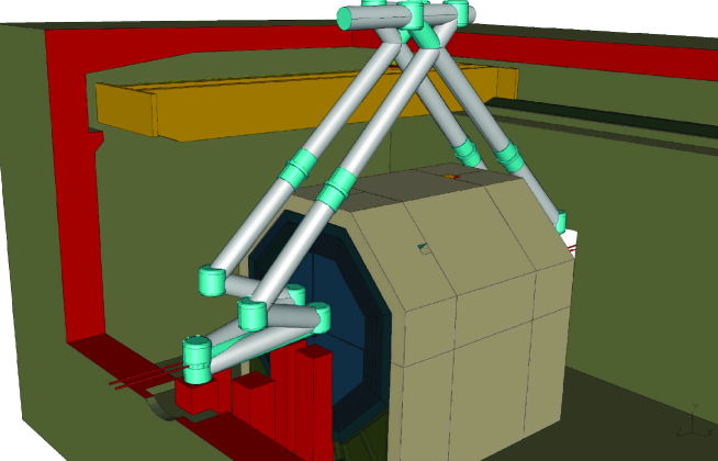
The DESY-Zeuthen group has considered an optical cavity at the wave level, its pumping by short laser pulses, diffraction losses, etc. Klemz2005 . The scheme of their cavity is shown in Fig. 14. In this study, truncated Gaussian beams were used. The results are in agreement with those given above for flat-top laser beams. Of course, consideration at the wave level is much more informative as it allows simulation of diffraction losses and propagation of different laser modes in the cavity. A possible layout of the cavity in the detector hall is shown in Fig. 15. In this design, the laser is situated on the surface; it may be better to hide the cavity under the detector.
This study of the cavity is only the first step. Now we need a more detailed considerations of all technical aspects of such a cavity and pumping laser with participation of people who are experienced in this field and are experts in laser technologies. As the result of the next step, we should understand what is well established and does not need an additional proofe and what needs additional experimental checks. Participation of recognized laser experts in these developments and their critical expertise will be sufficient for convincing the ILC community and politicians in the feasibility of the photon collider, but before construction of the real laser system we certainly need to organize the experimental laser group and construct a prototype in order to get experience and make the final design more reliable. There are some plans of such a facility at ATF2 at KEK ATF2 . Similar, but less powerful, laser cavities are also developed for beam diagnostic at the ILC and for the laser positron source.
Though the cavity reduces substantially the required laser energy, the laser should still be very powerful. All technologies necessary for such a laser exist, namely: the chirped pulse technique, adaptive optics, diode pumping, etc. According to LLNL estimation, the cost of one such laser is about $ 10 M Gronberg-snow05 . The photon collider needs two such lasers and one–two spares.
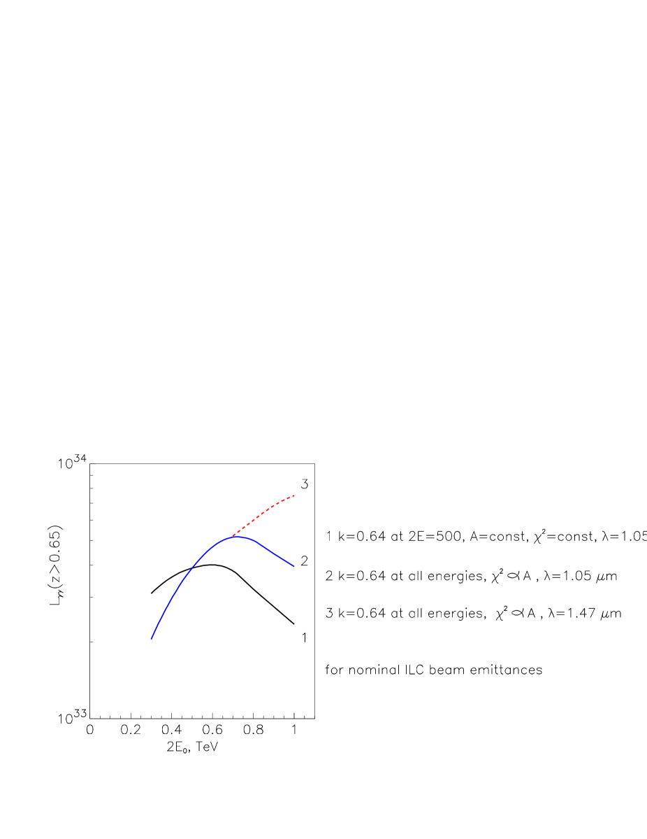
The same laser with the 1 m wavelength can be used up to the ILC energy GeV. At higher energies, the luminosity decreases due to pair creation in the conversion region in collision of the high-energy and laser photons GKST83 ; TEL95 and due to the decrease of the Compton cross section, see Fig. 16. For the energy TeV, the reduction of the luminosity due to this effect is about a factor of 2–3 compared to the optimum case. For the high energies it is desirable to have a wavelength of about 1.5–2 m. The technical feasibility of such a laser has not been studied yet.
I.7 Summary on the photon collider. The next steps.
A crab crossing angle of 25 mrad is the minimum crossing angle compatible with the photon collider. It is acceptable for operation as well, since the decrease of is small. However, the people prefer smaller angles in order to somewhat increase the detection efficiency for several processes (detection of small angles is needed for suppresion of some background processes). If the ILC is optimized only for , then the photon collider is not possible at all. On the other hand, the angle of 20 mrad is considered as one of possibilities for , which is very close to 25 mrad. In order to facilitate a transition to the photon collider the best would be the choice of the same angle for and ,, i.e. 25 mrad. As alternative one can use the scheme 3 in Fig. 8 which requires displacement of the detector and the final focus system.
In order to fix the crossing angle a optimize , a more detailed simulation of beam losses is required, as well as a more detailed design of the quad (which already seems good).
In order to increase it is desirable to decrease emittances in the DRs.
It is necessary to develop the final focus system for the photon collider with a small and understand whether it is compatible with or needs different hardware.
There exist ideas for the photon collider beam dump, detailed consideration is necessary.
There are some studies of the laser optical cavity for the photon collider, the next steps is consideration of all technological aspects, which requires participation of laser experts (needs money).
At the photon collider, the angle of about mrad is occupied by laser beams; this should be taken into account in the design of one of the detectors.
A decision about the status of the photon collider in ILC project should be made expediciuosly, because a) the photon collider determines design of many ILC elements; b) people will join to the development of the photon collider only if it is a part of the ILC and has political and financial support.
II ELECTRON-ELECTRON COLLIDER
Electron-electron collider presents a very unique possibility for study of many phenomena at the ILC under very clean conditions (without background from annihilation processes). Physics in collisions was discussed at several workshops (organized by C .Heusch) and proceedings are published emem . Such type of collisions requires minimum modification of the ILC, mainly in the final-focus system; nevertheless, this requires attention of accelerator people. Due to the beam repulsion, the attainable luminosity is by a factor of 5 lower than in collisions. At Snowmass, P.Bambade Bambade-snow05 discussed the possibility of in the scheme with a 2 mrad collision angle (where quads deflect outgoing beams). It was shown that the final focus system can be readjusted to in the case of more-round than optimal beams, with an additional loss in the luminosity by a factor of 2 and larger beamstrahlung. More studies are needed.
In summary: this option is important, and though seems simple technically (change of the magnet polarity), in reality its realization needs careful consideration of all accelerator parts, and solutions are not always simple.
III GIGA-Z
Physics requirements for GigaZ were considered at Snowmass by K. Mönig Monig-GZ . Only one remark here. GigaZ needs polarized beams with a small energy spread. The scheme with an undulator at GeV and further deceleration gives a large energy spread, so a bypass is needed. Effects of the wakefield in the main linac in GigaZ operation was considered at Snowmass by K. Kubo Kubo . Undulator positron source in the GigaZ option was discussed by D. Scott Scott .
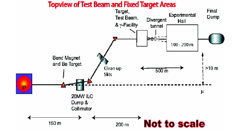
IV FIXED TARGET EXPERIMENTS
Fixed target experiments are traditional in particle physics and should be not ignored at the ILC Mtingwa ; Kolomensky ; Kanemura . For this purpose one can use the spent electron beam after the IP and deflect it from the beam dump to the experimental area. It consists of clean-up slits, a target area for production of the photon beam using crystal or laser targets, divergent tunnel, experimental hall and final dump. All together occupy more than one km in length, Fig. 17 Mtingwa . In order to reduce overlapping of events, it is attractive to consider the possibility of filling the ILC train by low-charge bunches between the primary ILC bunches and to deflect them by kickers for fixed target experiments.
If this option is accepted, it considerably influences the design of the ILC interaction region.
References
- (1) B. Badelek et. al., The Photon Collider at TESLA, Intern. Journ. Mod. Phys. A 30 (2004) 5097-5186, hep-ex/0108012.
- (2) V. I. Telnov, Photon collider at ILC, talk at the Second ILC Accelerator workshop, Snowmass, GG6 group, Colorado, August 14-27,2005.
- (3) B. Parker, QDO external field compensation possibilities for gamma-gamma, talk at the Second ILC Accelerator workshop, Snowmass, GG6 group, Colorado, August 14-27,2005.
- (4) V. I. Telnov, Crossing angle at the photon collider, the talk at Intern. Linear Collider Workshop (LCWS 2005), Stanford, California, 18-22 Mar 2005, physics/0507134.
- (5) V. I. Telnov, Status of gamma gamma, gamma electron colliders, Proc. of Intern. Conf. on the Structure and Interactions of the Photon (Photon 99), Freiburg, Germany, 23-27 May 1999, published in Nucl. Phys. Proc. Suppl. 82 (2000) 359.
- (6) V. I. Telnov, Photon collider at TESLA, Nucl. Instrum. Meth. A 472 (2001) 43, hep-ex/0010033.
- (7) A. Seryi, Discussion of gamma-gamma parameters, talk at the Second ILC Accelerator workshop, GG6 group, Snowmass, Colorado, August 14-27,2005.
- (8) A. Wolski, Low-Emittance Issues for ILC Damping Rings, talk at the Second ILC Accelerator workshop, GG6 group, Snowmass, Colorado, August 14-27,2005.
- (9) P. Raimondi and A. Seryi, Phys. Rev. Lett. 86, 3779 (2001).
- (10) L. I. Shekhtman and V. I. Telnov, A conception of the photon collider beam dump, physics/0411253. Proc. of Intern. Conf. on Linear Colliders (LCWS 04), Paris, France, 19-24 Apr 2004.
- (11) I. Will, T. Quast, H. Redlin and W. Sandner, A laser system for the TESLA photon collider based on an external ring resonator, Nucl. Instrum. Meth. A 472 (2001) 79.
- (12) G. Klemz, K. Monig and I. Will, Design study of an optical cavity for a future photon collider at ILC, DESY-05-098, physics/0507078.
- (13) B. I. Grishanov et al. [ATF2 Collaboration], ATF2 proposal, SLAC-R-771.
- (14) G. Gronberg, Options Photon Collider Laser Facilities, talk at the Second ILC Accelerator workshop, GG6 group, Snowmass, Colorado, August 14-27,2005.
- (15) Proceedings of the electron-electron linear collider workshops, ed. C.Heusch, Intern. J. of Mod. Physics A 13 (1995) 2217, 15 (2000) 2347, 18 (2003) 2733.
- (16) P. Bambade, Which beam parameters for ? Talk at the Second ILC Accelerator workshop, GG6 group, Snowmass, Colorado, August 14-27,2005.
- (17) K. Mönig, Physics requirements for GigaZ, Talk at the Second ILC Accelerator workshop, GG6 group, Snowmass, Colorado, August 14-27,2005.
- (18) K.Kubo, Effect of Wake in Main Linac in Giga-Z Operation, Talk at the Second ILC Accelerator workshop, GG6 group, Snowmass, Colorado, August 14-27,2005.
- (19) D. Scott, Undulator positron source and GigaZ option, Talk at the Second ILC Accelerator workshop, GG6 group, Snowmass, Colorado, August 14-27,2005.
- (20) S. Mtingwa, Fixed target experiments at ILC: overview, Second ILC Accelerator workshop, GG6 group, Snowmass, Colorado, August 14-27,2005.
- (21) Yu. Kolomensky, General Perspectives and Möller Scattering, Second ILC Accelerator workshop, GG6 group, Snowmass, Colorado, August 14-27,2005.
- (22) S. Kanemura, A Possibility of Measuring LFV couplings through the Deep Inelastic Process of eN X, Second ILC Accelerator workshop, GG6 group, Snowmass, Colorado, August 14-27,2005.
- (23) I. F. Ginzburg, G. L. Kotkin, V. G. Serbo, V. I. Telnov, Nucl. Instr. & Meth. 205 (1983) 47.
- (24) V. I. Telnov, Nucl. Instr. & Meth. 355 (1995) 3.