Introduction to microstructured optical fibers
M. Yan
myan@ieee.org
Network Technology Research Centre, Nanyang Technological University
50 Nanyang Drive, Singapore, 637553
Abstract
This article recounts definition, classification, history, and applications of microstructured optical fibers.
1 Definition and Varieties
Since the first microstructured optical fiber (MOF) demonstrated by Knight et al. [1], research on this class of optical waveguides has thrived. To date, lots of fibers with air-hole inclusions were reported. In fact, to meet different application purposes, the “holey” fibers experience constant alterations and they evolve divergently in many directions. Some of fibers deviate much in structure from that in the very first publication. To address these fibers, several names have been coined—they include photonic crystal fiber (PCF), holey fiber (HF), microstructured optical fiber (MOF), and photonic bandgap fiber (PBGF). “PCF”, “HF”, and “MOF” are defined from structure point of view, whereas “PBGF” are defined from optical-property point of view. Among the names, MOF is the most general one. In fact, MOF can be used to address all fibers which have their feature size at micrometer (or submicrometer) scale. The rest names can be considered as subsets of MOF, and they can’t address rigorously all MOFs reported in general. For example, “PCF” is not appropriate for fibers which lack of periodic cladding; “HF” is not appropriate for those fibers made of all solid materials; “PBGF” is certainly only applicable for those guiding light by cladding’s photonic bandgap (PBG).
Figure 1 and 2 show novel MOFs made or proposed during recent years. While PBG fibers (except the air-silica Bragg fiber) shown in Fig. 2 are observed to adhere to the term “photonic crystal (PC)” faithfully, index-guiding fibers sometimes can be nothing to do with photonic crystal (for example, the air-clad fiber). We will come across most of the fibers displayed in these two figures later in Section 3 of this article.
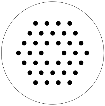
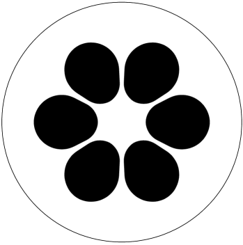
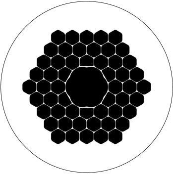
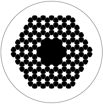
Index-guiding MOFs not presented in Fig. 1 include hole-assisted MOFs [13, 14], double-clad index-guiding MOF [3], and “graded-index” MOF [15]. PBG-guiding MOFs not presented in Fig. 2 include hollow-core Bragg fiber [16] and solid-core Bragg fiber [17]. Heterostructured PCFs [18] are not shown in either of the figures.
Having mentioned all these MOF varieties, we will however limit discussions on MOFs with periodic cladding. Hence in certain places an MOF can be also referred to as PCF without ambiguity.
A Index-guiding v.s. PBG-guiding
In fact, the index-guiding fiber can be considered as a PBG-guiding fiber in the sense that the propagation constant of a core mode can not be supported by the cladding. The bandgap region used in an index-guiding fiber is the largest one possessed by the cladding, i.e., the region below the cladding’s radiation line in plot ( is the -axis value, and , with free-space wavelength). In this region, the cladding can’t support any propagating mode, as the lightwave (wavelength at ) in a homogeneous material (refractive index at ) should have its smallest propagation constant at . And the smallest propagation constant happens when the light propagates as a plane wave. Any other mode of propagation will increase its propagation constant.
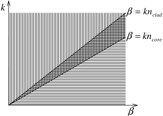
Refer to Fig. 3, as an infinitely-extending rod of high-index () is introduced in an infinitely-extending low-index material (), due to the fact that the high-index material has its radiation line positioned lower than that for the low-index material , there exists a region in the plot (enclosed by and ) in which light can propagating in the rod but not in the background material. This is how a conventional step-index fiber works.
Now as the homogeneous background material is replaced by a photonic crystal, the cladding’s radiation line becomes , where is effective index of the fundamental space-filling mode (FSM) of the crystal structure. The main difference between a composite and a homogeneous material is that, other than the region below its radiation line, there are, possibly, some small regions above the radiation line, in which light can’t propagate in the crystal [Fig. 3(b)]. Indeed, we can make use of these small regions to confine light in a material whose index is smaller than . This is how a photonic bandgap fiber works.
B PBG-guiding v.s. Guidance by Antiresonant-reflection
To differentiate these two terms, we have to recall the history of the antiresonant-reflecting optical waveguide (ARROW).
Multi-layered substrate was proposed by Ash to replace homogeneous substrate in slab waveguide to guide surface wave in 1970 [19] 111This paper is cited in [20], but is not traceable at this moment by me.. Such problem was then theoretically treated by A. J. Fox in 1974 [20]. Both papers call such waveguide as grating waveguide. However, Fox did not show wave guidance in a low-index material. Two years later, Yeh et al. theoretically demonstrated, by use of Floquet-Bloch theorem, guidance in low-index material (air) for a slab waveguide with layered cladding [21]. Such waveguide is named by Yeh et al. as Bragg waveguide. In this paper, very importantly, they used a third material in core region (air), and cladding is a periodic structure made of two solid materials. Half a year later, Cho from Bell Laboratories experimentally confirmed confined propagation in such waveguides [22]. In 1978, Yeh et al. put one step further from slab-type waveguides, and proposed to use multi-layered cylinders to propagate light in an air column [23]. Such fiber is named as Bragg fiber. Both slab-type Bragg waveguide and the Bragg fiber were not investigated further until eight years later in 1986 Duguay et al. fabricated on silicon wafer a Bragg waveguide [24]. Their waveguide is however formed by two material, i.e., core material is one of the cladding materials. But Duguay et al. rename the waveguide as “antiresonant-reflecting optical waveguide” (ARROW) and attribute the guidance to the antiresonance of the high-index layer (analogous to a Fabry-Perot resonator) placed adjacent to the low-index core. To some extent, this paper revives the research on such waveguides. A 2D ridge-type ARROW was also fabricated by Freye et al. in 1994 [25].
Research on ARROW should really be considered as pioneer work on photonic crystal waveguides (bandgap guidance). In fact, these work can easily lead to the concept of photonic crystal. However, as the authors did not generalize the layered dielectric media to other dimensions, their impact was limited.
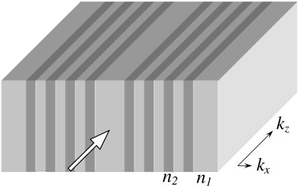
Let’s review what is the traditional ARROW model made popular by Duguay et al.. Refer to the simplest slab-type ARROW shown in Fig. 4, the model states that properties of the high-index layers around the core determines the guidance in the low-index core region. When the high-index cladding layers are in resonance with the core mode, light is relayed outwards laterally by the high-index layers. When the layers are not in resonance (in antiresonance) with the core mode, light is rejected and confinement in low-index core region is achieved. The resonant and antiresonant conditions can be quantitatively derived from the Bragg reflection conditions for the lateral wavevector component (Fig. 4). The lateral phase variation in a high-index layer is
| (1) |
where is width of high-index layers. If is equal to odd number of , the high-index layers are considered to be in antiresonant state with the core mode. Or we can say Bragg reflection is met along -direction. The core mode hence has the least radiation loss under this condition. If is equal to even number of , the high-index layers are considered to be in resonant state with the core mode. The core mode experiences rapid dissipation after being launched.
This traditional ARROW model does explain successfully light confinement in a material of lower index. It even does not acknowledge the cladding to be periodic (which suggests that we might have missed certain things as nowadays we explicitly use a periodic PC cladding to confine light in a lower index material). Also the model can accurately predict the exact highest-loss and lowest-loss wavelength points by considering the high-index layers in cladding to be in complete resonance and antiresonance, respectively. However, we would like to point out that ARROW is indeed just another name for regular waveguides whose guidance is achieved by the photonic bandgap effect. Antiresonance of cladding composite gives rise to a forbidden bandgap. And in fact, we should establish a equation
| cladding bandgap | completely antiresonant state of cladding | (2) | |||
In the ARROW model proposed by Duguay et al., the role of low-index layers in cladding region has been ignored. In fact, their antiresonance also contributes to the confinement of lightwave in core region222However, the antiresonance of the low-index layers has less contribution than that of the high-index layers to the confinement of lightwave. This can be easily explained by calculating a few lowest-order supermodes (or space-filling modes) of the cladding composite. The first group of modes have about lateral phase variation in the high-index layers. The next group of modes have about lateral phase variation in the high-index layers. For both mode groups, very little field is located in the low-index layers. If we plot the dispersion curves for these two groups of modes in a - diagram, the region in between of these two dispersion curve groups is the bandgap used for our guidance. As little field is located in low-index layers, this consequence is valid: some small variation in the low-index layer width little change in two mode groups’ dispersion curves little change in the bandgap In above argument, we have assumed the primary bandgap of the cladding is used for guidance. This makes sense, as ARROWs and PBGFs fabricated to date almost explicitly use bandgaps found among several lowest-order space-filling modes. . In other words, to better confine light in the core region, we need to tune the widths of both high- and low-index layers in cladding so that they meet their anti-resonance conditions together.
ARROW model is straightforward for slab-type waveguides shown in Fig. 4. Nice equations can be written down to determine wavelength points where the lowest and the highest leakage loss happen. However, it should be mentioned that such equations are difficult, if not impossible, to be analytically written down for a 2D PBG waveguide. For example, for the all-solid PBG fiber shown in Fig. 2(f), though the resonance conditions for the cladding high-index rods can be approximately written down using certain expression [26, 27], resonance condition for the low-index cladding region is not. Especially in such 2D waveguides a full transverse bandgap of the cladding is necessary for confining light. Hence we have to consider all wavevector components in the transverse direction for analyzing resonance and antiresonance conditions (remember we only considered -component of the wavevector for slab-type waveguide shown in Fig. 4).
At this point, we may conclude that the name “photonic crystal fiber” is sometimes misleading, as it gives us the impression that photonic bandgaps can only exist in periodic cladding structures. A consequence of the ARROW model is that the cladding of an PBG waveguide does not need to be periodic. Refer to Fig. 4, the most straightforward example would be: the high-index cladding layers can be of certain width to cause lateral phase variation, and they also can be thicker to introduce lateral phase variation. Besides, as far as the optimum confinement at a particular wavelength is concerned, the periodicity requirement of the cladding composite is automatically lifted in the case of Bragg fiber (and any other 2D PBG waveguide). This is owing to the fact that mode field in a Bragg fiber is represented by aperiodic Bessel functions333For a 2D PBG fiber like Bragg fiber, we would however be better off by using a periodic cladding in practice. There are several reasons. First, aperiodic cladding can only enhance guidance at a single wavelength point, not the whole cladding PBG window. And improvement in PBG guidance can always be achieved by including more cladding layers. Second, fabrication of periodic structure is easier than that of aperiodic structure. Third, periodic structure facilitates deployment of Bloch theorem in bandgap calculation. [23].
2 PCF Classification
Figure 5 shows the possible configurations of a PCF. This figure has generalized PCF to those made of a PC cladding and a PC core [18]. Though we only consider PCs made of two materials, it should be kept in mind that more materials can be involved. Structurally, only PCs exhibiting symmetry are presented owing to their ease of fabrication. Depending on fabrication method, other-latticed PCs should be able to exist.
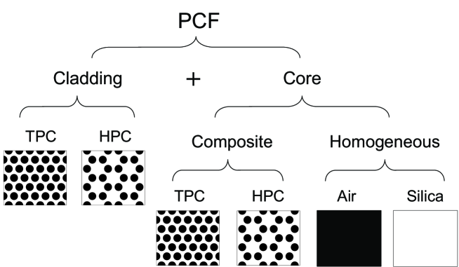
From Fig. 5, a particular two-material fiber can be named accurately by mentioning the cladding and core structures. For example, if the cladding is TPC and core is HPC, then the fiber can be referred to as a TPC-HPC fiber; for a fiber with TPC cladding and silica core, we can name it as solid-core TPC fiber; for a fiber with TPC cladding and air core, we can name it as air-core TPC fiber, etc.
Besides those shown in Fig. 5, we should mention that a MOF can have a homogeneous cladding and a PC core [28].
1 Triangular v.s. Honeycomb
These two terms are sometimes confusing. Early PCFs are made of circular air holes in silica background. Hence, we normally tell a PCF’s cladding type according to the placement of air holes. However, as PCF design gets complicated, such as air-guiding TPC fiber and HPC fiber shown in Fig. 2(a) and (b), the fiber cladding is more close to silica rods immersed in air background [8, 29]. If we define the lattice according to position of the silica pillars, traditional TPC (HPC) becomes HPC (TPC).
Addressing the lattice pattern of a PC can also be ambiguous without specifying corresponding lattice vectors. For a traditional HPC, if we use a second-level unit-cell, the crystal becomes a TPC [18].
In this thesis, we stick to traditional naming convention, i.e., a crystal structure is defined by the air hole positions, though the air holes may not be circular. Also, the primitive basis vectors are normally used for defining the crystal’s lattice pattern, unless otherwise stated.
3 Technology Review and Current Trends
A Index-guiding MOF
1 Technology Review
The possibility of fabricating a fiber whose cladding is made of photonic crystal was first proposed in [30] 444Here we would like to draw attention to the paper published in 1978 by Yeh et al. on Bragg fiber [23]. Strictly speaking, their work should be regarded as the first paper on fiber design employing a photonic crystal (1D) cladding. However, they did’t generalize the idea to 2D and 3D situations. Their work was put into practice by a group of people in MIT about 20 years later (for example, see [31] and [16]). This is quite similar to the case that 1D photonic crystal was first explained by Lord Rayleigh in 1887, but revived by E. Yablonovitch [32] and S. John [33] 100 years later. There are always some people ahead of time.. In this paper, Birks et al. theoretically showed that full 2D photonic bandgaps exist in an air-silica (holes-in-silica) photonic crystal (PC) when the off-plane wavevector component is large enough. And they suggest “a new type of optical fibre, the PBG fibre, is possible” by using “a periodic air/silica cladding surrounding a uniform core”. “The core can be solid silica or a hollow air region”. One year later, the same group published a paper on the first fabricated photonic crystal fiber (PCF) [1]. As the central defect is silica, the fiber does not guide light using PBG effect. Though Knight et al. have included the term “photonic crystal” in naming the waveguide, the fiber, in principle, is equivalent to a conventional step-index fiber (SIF). Lack of PBG guidance, however, does not prevent such fiber being exceptional. Knight et al. identifies an interesting property, i.e., it has is a very broad single-mode operation wavelength range (458nm1550nm for the fiber reported, with m and ). Their work attracted immediately lots of attention and related studies were carried out by different research groups around the world. More special waveguiding properties were reported. In year 1998, Mogilevtsev et al. theoretically studied group velocity dispersion (GVD) of PCFs [34], and found some novel dispersion properties, such as zero-dispersion point at short wavelength and large normal dispersion value at 1550nm, can be easily achieved by adjusting the fiber parameters ( and ). The dispersion tuning in such fibers was later overwhelmingly studied by researchers. To name a few, dispersion-flatten PCFs were studied in [35, 36, 37, 38, 39], dispersion-compensating PCFs were studied in [40, 41, 42, 43]. Remarkable birefringence property of PCFs were also reported on several occasions in the literature. They include [44, 45, 46, 4]. Nonlinear optics in PCFs is also demonstrated to be promising as the fibers can be fabricated with ultrahigh nonlinearity can be fabricated using large-sized cladding air holes and small silica core. Among all nonlinear effects, third-harmonic generation in PCF can be found in [47], four-wave mixing can be found in, for example, [48, 49], Raman effect can be found in [50, 51, 52], supercontinuum phenomenon can be found in, for example, [53, 54, 55] etc, etc.
It should be mentioned that beside using silica, other materials are also explored for, especially, index-guiding PCF design. The materials include high-lead silicate glass, tellurite glass, gallium lanthanum chalcosulfide glass, and also polymethyl-methacrylate (PMMA). The first three types of glasses have quite low softening temperature, hence they are also called soft glasses. Using these soft glasses to fabricate PCFs has been summarized in [56]. Two thermally-matched soft glasses have also been used to form an index-guiding PCF [6]. The first polymer PCF was reported in [57].
2 Trends
Though confinement loss of index-guiding MOF has been reduced to 0.48 dB/km [58], we don’t see immediate necessity to deploy such fiber into transmission system. There are several reasons for this: first of all, the loss is still higher than conventional step-index fiber; second, the cost is certainly higher as compared to standard commercial step-index fiber555MOF uses only pure silica, therefore its preform is cheaper in terms of material as compared to conventional SIFs where doping of chemical element is involved. But stacking of preform bundle is labor-intensive (there is currently no better way to prepare the preform) and the uncertainties involved during fabrication (dust contamination, fluctuation in pressure controlling etc) is higher than that for conventional fiber. Unless high-level automation is realized, it is correct to conclude that MOFs are more expensive.; third, compatibility (such as splicing) with existing system is still a problem. Index-guiding MOF can indeed be tailored to have some excellent property in certain aspect, but not all aspects. In next few years, application of such fibers would, most probably, still be limited to subsystems or optical devices. In particular, exploration of high nonlinearity and high birefringence properties in MOFs would be likely to attract fair amount of attention. Its deployment in fiber lasers will also be a very meaningful research topic.
B PBG-guiding MOF
1 Technology Review
The first PCF whose guidance is due to existence of its cladding PC’s photonic bandgap (PBG) was reported in year 1998 by Knight et al. [59]. However, the propagating light concentrates in silica portion within the core region, which is inevitable as the fiber’s cladding is of honeycomb lattice and the core is made of air-silica composite [18]. The first air-guiding PBG fiber was reported in 1999 by Cregan et al. [60]. The transmission spectrum is measured using a short fiber of a few centimeter length. It is claimed to be single-mode. However, the authors didn’t convincingly prove their point. Fiber technique is greatly improved in the following several years. By year 2003, loss is greatly reduced to 13dB/km at 1500nm by Corning [7]. And in year 2004, lowest fiber loss is even as small as 1.2 dB/km [61, 62].
Air-guiding PBG fiber was originally proposed for ultra-low loss optical communication. In addition, it was said that signal propagating in such fiber is “free of group velocity dispersion”. However, to date, we have achieved neither of these two goals. The loss is still high compared to conventional step-index fibers. The group velocity dispersion is quite large, especially near bandgap edges [63]. Recently it is found that there are uncertainties in such fiber’s polarization mode dispersion (PMD) property [64]. What’s more, a true low-loss single-mode air-guiding PBG fiber has never been fabricated. All these factors would prevent such fiber from being deployed for long-haul transmission link at this moment. However, due to the unique hollow-core feature, it has thrived in areas like high-power pulse delivery [65, 66], nonlinear optics in gases [67, 68], atom guiding [69], and sensing applications [70], etc.
Besides hollow-core PBG fibers, there exist several types of solid-core PBG fibers. Theoretical work on this can be traced to [71] and [27]. Experimentally, two soft glasses have been used to fabricate a PBG fiber by Luan et al. [12]. Doped silica has also been used to form scatterers in the cladding region of a solid-core PBG fiber [72]. It was observed that such low-index contrast PBG fiber has wider transmission window [72]. However, no particular application has so far been identified using these types of fibers, largely due to the fact that light is confined in a solid core, which is quite analogues to conventional step-index fiber.
Besides using 2D PC to form a PBG fiber’s cladding, cylindrical-1D PC was also exploited for confining light in a hollow core. Omniguide fiber, or Bragg fiber, was first fabricated by Fink et al [31]. The same group has demonstrated using Bragg fiber to deliver high-power laser [16]. Recently, they have produced such fiber with transmission window near IR (0.85 to 2.28m) wavelength [73]. Vienne et al. fabricated the so-called air-silica Bragg fiber whose cladding highly resembles a cylindrical-1D PC [11]. Very similar Bragg fiber has also been fabricated very recently by Agyros et al. using air and polymer [74]. However, the air-silica Bragg fiber suffers from a very fragmented transmission window [75]. Whereas Bragg fibers made by Fink’s group has three materials (core is made of air, cladding is made of soft glass and polymer bi-layers), people have also tried to fabricate Bragg fibers using two solid materials (core material is one of the cladding materials with lower index). These include [76, 17].
2 Trends
The traditional air-guiding PBG fiber uses a TPC cladding. Such 2D PC was recently generalized by Yan et al [29]. It is found that by slightly modifying the PC structure, it is possible to tune the bandgap favorably for different purposes, e.g., smaller leakage or even true single-mode air-guiding etc. A hollow-core fiber with such PC cladding was theoretically studied in [77]. The fiber has very wide surface-mode-free PBG guiding wavelength range and it promotes single-mode operation. Technologically speaking, fabrication of such fiber does not impose any additional difficulty as compared to conventional air-guiding PBG fiber. It will be very interesting to see an actual fiber in near future.
HPC cladding was not considered to achieve air guiding until its capability was theoretically validated by Yan et al. [78]. Such fiber’s leakage loss was later studied in [8]. The hollow-core of such fiber can be less than 6m in diameter, which suggests single-mode operation is possible. Also the surface-mode problem has been completely mitigated in such fibers. Air-guiding HPCF can be a competitive alternative to existing air-guiding PBG fibers if they can be fabricated successfully.
As we have mentioned, the first fabricated honeycomb PBG fiber has an air-silica composite core [59]. The idea of using two different pieces of PCs to form a fiber (core and cladding are both composite) was put forward by Yan et al. [18]. Depends on the design, PBG-guiding or index-guiding can be achieved in such fibers. Such fibers are expected to perform better in application of gas or liquid sensor. Also, they should have important applications that exploit the phenomenon of discrete soliton [79].
As compared to air-silica PBGFs, Bragg fiber suffers significantly higher radiation loss. New types of high index-contrast, low-absorption dielectric materials which are matched in thermal properties (softening temperatures, expansion coefficients, viscosity) and chemical properties (non-diffusive to each other) need to be identified to fabricate more robust hollow-core Bragg fiber. Preferably, the guidance should be around 1550nm wavelength point. For air-silica Bragg fiber fabricated by Vienne et al., more theoretically work is necessary to understand its leakage loss. It might be possible to prevent the fragmentation of the transmission window by an improved design. If that indeed happens, we can reduce the overall leakage loss by increasing the number of air-hole rings in the cladding.
Application-wise, high-power pulse or beam delivery will still be an important direction to go [80]. Nonlinear optics in such fibers with gas- or liquid-filled core will also be very interesting.
References
- [1] J. C. Knight, T. A. Birks, P. S. J. Russell, and D. M. Atkin, “All-silica single-mode optical fiber with photonic crystal cladding,” Opt. Lett. 21, 1547–1549 (1996).
- [2] B. J. Eggleton, C. Kerbage, P. S. Westbrook, R. S. Windeler, , and A. Hale, “Microstructured optical fiber devices,” Opt. Express 9(13), 698–713 (2001).
- [3] “Crystal Fibre A/S,” URL http://www.crystal-fiber.com.
- [4] H. Kubota, S. Kawanishi, IEEE, S. Koyanagi, M. Tanaka, and S. Yamaguchi, “Absolutely single polarization photonic crystal fiber,” IEEE Photon. Technol. Lett. 16(1), 182–184 (2004).
- [5] N. A. Issa, M. A. van Eijkelenborg, M. Fellew, F. Cox, G. Henry, , and M. C. J. Large, “Fabrication and study of microstructured optical fibers with elliptical holes,” Opt. Lett. 29(12), 1336–1338 (2004).
- [6] X. Feng, T. M. Monro, P. Petropoulos, V. Finazzi, and D. Hewak, “Solid microstructured optical fiber,” Opt. Express 11(18), 2225–2230 (2003).
- [7] C. M. Smith, N. Venkataraman, M. T. Gallagher, D. Müller, J. A. West, N. F. Borrelli, D. C. Allan, and K. W. Koch, “Low-loss hollow-core silica/air photonic bandgap fibre,” Nature 424, 657–659 (2003).
- [8] M. Yan, P. Shum, and J. Hu, “Design of air-guiding honeycomb photonic bandgap fiber,” Opt. Lett. 30, 465–467 (2005).
- [9] J. Broeng, T. Søndergaard, S. E. Barkou, P. M. Barbeito, and A. Bjarklev, “Waveguiding by the photonic bandgap effect in optical fibres,” J. Opt. A 1, 477–482 (1999).
- [10] M. Yan, X. Yu, P. Shum, C. Lu, and Y. Zhu, “Honeycomb photonic bandgap fiber with a modified core design,” IEEE Photon. Technol. Lett. 16, 2051–2053 (2004).
- [11] G. Vienne, Y. Xu, C. Jakobsen, H.-J. Deyerl, J. B. Jensen, T. Sorensen, T. P. Hansen, Y. Huang, M. Terrel, R. K. Lee, N. A. Mortensen, J. Broeng, H. Simonsen, A. Bjarklev, and A. Yariv, “Ultra-large bandwidth hollow-core guiding in all-silica Bragg fibers with nano-supports,” Opt. Express 12, 3500–3508 (2004).
- [12] F. Luan, A. K. George, T. D. Hedley, G. J. Pearce, D. M. Bird, J. C. Knight, and P. S. J. Russell, “All-solid photonic bandgap fiber,” Opt. Lett. 29, 2369–2371 (2004).
- [13] T. Hasegawa, E. Sasaoka, M. Onishi, M. Nishimura, Y. Tsuji, and M. Koshiba, “Hole-assisted lightguide fiber for large anomalous dispersion and low optical loss,” Opt. Express 9(13), 681–686 (2001).
- [14] M. Yan, P. Shum, and C. Lu, “Hole-assisted multiring fiber with low dispersion around 1550 nm,” IEEE Photon. Technol. Lett. 16(1), 123–125 (2004).
- [15] M. van Eijkelenborg, A. Argyros, A. Bachmann, G. Barton, M. Large, G. Henry, N. Issa, K. Klein, H. Poisel, W. Pok, L. Poladian, S. Manos, and J. Zagari, “Bandwidth and loss measurements of graded-index microstructured polymer optical fibre,” IEE Electron. Lett. 40(10), 592–593 (2004).
- [16] B. Temelkuran, S. D. Hart, G. Benoit, Johnnopoulos, and Y. Fink, “Wavelength-scalable hollow optical fibres with large photonic bandgaps for laser transmission,” Nature 420, 650–653 (2002).
- [17] T. K. Y. Matsuura and M. Miyagi, “Fabrication of silica-core photonic bandgap fiber with multilayer cladding,” in Optical Fiber Communication, p. WI1 (Los Angeles, USA, 2004).
- [18] M. Yan, P. Shum, and X. Yu, “Heterostructured Photonic Crystal Fiber,” IEEE Photon. Technol. Lett. 17(7), 1438–1440 (2005).
- [19] E. A. Ash, “Grating surface wave waveguides,” in Int. Microwave Symp. (Newport Beach. Calif., 1970).
- [20] A. J. Fox, “The grating guide—a component for integrated optics,” Proceedings of the IEEE pp. 644–645 (1974).
- [21] P. Yeh and A. Yariv, “Bragg reflection waveguides,” Opt. Comm. 19(3), 427–430 (1976).
- [22] A. Y. Cho, A. Yariv, and P. Yeh, “Observation of confined propagation in Bragg waveguides,” Appl. Phy. Lett. 30(9), 471–472 (1977).
- [23] P. Yeh, A. Yariv, and E. Marom, “Theory of Bragg fiber,” J. Opt. Soc. Am. 68, 1196–1201 (1978).
- [24] M. A. Duguay, Y. Kokubun, T. L. Koch, and L. Pfeiffer, “Antiresonant reflecting optical waveguides in Si-Si multilayer structures,” Appl. Phy. Lett. 49(1), 13–15 (1986).
- [25] R. Freye, T. Delonge, P. Bönsch, and H. Fouckhardt, “Experimental and numerical investigations of two-dimensional “Antiresonant Reflecting Optical Waveguides” (ARROWS) based on AIGaAs/GaAs,” in Conference on Lasers and Electro-Optics Europe (CLEO/Europe), pp. 291–291 (1994).
- [26] N. M. Litchinitser, S. C. D. P. E. Steinvurzel, B. J. Eggleton, T. P. White, R. C. McPhedran, and C. M. de Sterke, “Application of an ARROW model for designing tunable photonic devices,” Opt. Express 12(8), 1540–1550 (2004).
- [27] M. Yan, H. Liu, and P. Shum, “Loss property of photonic bandgap fiber made of high-index cylinders in low-index host material,” in International Conference on Communications, Circuits and Systems (ICCCAS) (Chengdu, China, 2004).
- [28] M. Yan and P. Shum, “Antiguiding in microstructured optical fibers,” Opt. Express 12, 104–116 (2004).
- [29] M. Yan and P. Shum, “Improved air-silica photonic crystal with a triangular airhole arrangement for hollow-core photonic bandgap fiber design,” Opt. Lett. 30(15), 1920–1922 (2005).
- [30] T. A. Birks, P. J. Roberts, P. S. J. Russell, D. M. Atkin, and T. J. Shepherd, “Full 2-D photonic bandgaps in silica/air structures,” IEE Electron. Lett. 31(22), 1941–1943 (1995).
- [31] Y. Fink, D. J. Ripin, S. Fan, C. Chen, J. D. Joannepoulos, and E. L. Thomas, “Guiding optical light in air using an all-dielectric structure,” J. Lightwave Technol. 17(11), 2039–2041 (1999).
- [32] E. Yablonovitch, “Inhibited Spontaneous Emission in Solid-State Physics and Electronics,” Phys. Rev. Lett. 58(20), 2059–2062 (1987).
- [33] S. John, “Strong localization of photons in certain disordered dielectric superlattices,” Phys. Rev. Lett. 58(23), 2486–2489 (1987).
- [34] D. Mogilevtsev, T. A. Birks, and P. S. J. Russell, “Group-velocity dispersion in photonic crystal fibers,” Opt. Lett. 23(21), 1662–1664 (1998).
- [35] A. Ferrando, E. Silvestre, J. J. Miret, J. A. Monsoriu, M. V. Andés, and P. S. J. Russell, “Designing a photonic crystal fibre with flattened chromatic dispersion,” IEE Electron. Lett. 35(4), 325–327 (1999).
- [36] A. Ferrando, E. Silvestre, J. J. Miret, , and P. Andrés, “Nearly zero ultraflattened dispersion in photonic crystal fibers,” Opt. Lett. 25(11), 790–792 (2000).
- [37] W. Reeves, J. Knight, P. Russell, and P. Roberts, “Demonstration of ultra-flattened dispersion in photonic crystal fibers,” Opt. Express 10(14), 609–613 (2002).
- [38] G. Renversez, B. Kuhlmey, and R. McPhedran, “Dispersion management with microstructured optical fibers: Ultraflattened chromatic dispersion with low losses,” Opt. Lett. 28(12), 989–991 (2003).
- [39] K. Saitoh, M. Koshiba, T. Hasegawa, and E. Sasaoka, “Chromatic dispersion control in photonic crystal fibers: Application to ultra-flattened dispersion,” Opt. Express 11(8), 843–852 (2003).
- [40] T. A. Birks, D. Mogilevtsev, J. C. Knight, and P. S. Russell, “Dispersion compensation using single-material fibers,” IEEE Photon. Technol. Lett. 11(6), 674–676 (1999).
- [41] L. P. Shen, W.-P. Huang, G. X. Chen, and S. S. Jian, “Design and optimization of photonic crystal fibers for broad-band dispersion compensation,” IEEE Photon. Technol. Lett. 15(4), 540–542 (2003).
- [42] B. Zsigri, J. Lægsgaard, and A. Bjarklev, “A novel photonic crystal fibre design for dispersion compensation,” J. Opt. A: Pure Appl. Opt. 6(7), 717–720 (2004).
- [43] F. Gérôrme, J.-L. Auguste, and J.-M. Blondy, “Design of dispersion-compensating fibers based on a dual-concentric-core photonic crystal fiber,” Opt. Lett. 29(23), 2725–2727 (2004).
- [44] A. Ortigosa-Blanch, J. C. Knight, W. J. Wadsworth, J. Arriaga, B. J. Mangan, T. A. Birks, and P. S. J. Russell, “Highly birefringent photonic crystal fibers,” Opt. Lett. 25(18), 1325–1327 (2000).
- [45] T. P. Hansen, J. Broeng, S. E. B. Libori, E. Knudsen, A. Bjarklev, J. R. Jensen, and H. Simonsen, “Highly birefringent index-guiding photonic crystal fibers,” IEEE Photon. Technol. Lett. 13(6), 588–560 (2001).
- [46] K. Suzuki, H. Kubota, S. Kawanishi, M. Tanaka, and M. Fujita, “Optical properties of a low-loss polarization-maintaining photonic crystal fiber,” Opt. Express 9(13), 676–680 (2001).
- [47] A. Efimov, A. J. Taylor, F. G. Omenetto, J. C. Knight, W. J. Wadsworth, and P. S. J. Russell, “Phase-matched third harmonic generation in microstructured fibers,” Opt. Express 11(20), 2567–2576 (2003).
- [48] J. H. Lee, W. Belardi, K. Furusawa, P. Petropoulos, Z. Yusoff, T. M. Monro, and D. J. Richardson, “Four-wave mixing based 10-Gb/s tunable wavelength conversion using a holey fiber with a high SBS threshold,” IEEE Photon. Technol. Lett. 15(3), 440–442 (2003).
- [49] K. K. Chow, C. Shu, C. Lin, and A. Bjarklev, “Polarization-insensitive widely tunable wavelength converter based on four-wave mixing in a dispersion-flattened nonlinear photonic crystal fiber,” IEEE Photon. Technol. Lett. 17(3), 624–626 (2005).
- [50] Z. Yusoff, J. H. Lee, W. Belardi, T. M. Monro, P. C. Teh, and D. J. Richardson, “Raman effects in a highly nonlinear holey fiber: Amplification and modulation,” Opt. Lett. 27(6), 424–426 (2002).
- [51] C. J. S. de Matos, K. P. Hansen, and J. R. Taylor, “Experimental characterisation of Raman gain efficiency of holey fibre,” IEE Electron. Lett. 39(5), 424–425 (2003).
- [52] M. Fuochi, F. Poli, S. Selleri, A. Cucinotta, , and L. Vincetti, “Study of Raman amplification properties in triangular photonic crystal fibers,” J. Lightwave Technol. 21(10), 2247–2254 (2003).
- [53] A. V. Husakou and J. Herrmann, “Supercontinuum generation in photonic crystal fibers made from highly nonlinear glasses,” Applied Physics B 77(2-3), 227–234 (2003).
- [54] T. Hori, J. Takayanagi, N. Nishizawa, and T. Goto, “Flatly broadened, wideband and low noise supercontinuum generation in highly nonlinear hybrid fiber,” Opt. Express 12(2), 317–324 (2004).
- [55] K. M. Hilligsoe, T. V. Andersen, H. N. Paulsen, C. K. Nielsen, K. Molmer, S. Keiding, R. Kristiansen, K. P. Hansen, and J. J. Larsen, “Supercontinuum generation in a photonic crystal fiber with two zero dispersion wavelengths,” Opt. Express 12(6), 1045–1954 (2004).
- [56] X. Feng, A. K. Mairaj, D. W. Hewak, , and T. M. Monro, “Nonsilica glasses for holey fibers,” J. Lightwave Technol. 23(6), 2046–2054 (2005).
- [57] M. van Eijkelenborg, M. Large, A. Argyros, J. Zagari, S. Manos, N. A. Issa, I. M. Bassett, S. C. Fleming, R. C. McPhedran, C. M. de Sterke, and N. A. P. Nicorovici, “Microstructured polymer optical fibre,” Opt. Express 9(7), 319–327 (2001).
- [58] M. Nielsen, C. Jacobsen1, N. Mortensen, J. Folkenberg, , and H. Simonsen, “Low-loss photonic crystal fibers for transmission systems and their dispersion properties,” Opt. Express 12(7), 1372–1376 (2004).
- [59] J. C. Knight, J. Broeng, T. A. Birks, and P. S. J. Russell, “Photonic band gap guidance in optical fibers,” Science 282, 1746–1748 (1998).
- [60] R. F. Cregan, B. J. Mangan, J. C. Knight, T. A. Birks, P. S. J. Russell, P. J. Roberts, and D. C. Allan, “Single-mode photonic band gap guidance in air,” Science 285, 1537–1539 (1999).
- [61] B. J. Mangan, L. Farr, A. Langford, P. J. Roberts, D. P. Williams, F. Couny, M. Manson, S. Coupland, R. Flea, H. Sabert, T. A. Birds, J. C. Knight, and P. S. J. Russell, “Low loss (1.7 dB/km) hollow core photonic bandgap fiber,” in Proc. Optical Fiber Communication Conference (Los Angeles, 2004).
- [62] P. J. Roberts, F. Couny, H. Sabert, B. J. Mangan, D. P. Williams, L. Farr, M. W. Mason, A. Tomlinson, T. A. Birks, J. C. Knight, and P. S. Russell, “Ultimate low loss of hollow-core photonic crystal fibres,” Opt. Express 13(1), 236–244 (2005).
- [63] K. Saitoh and M. Koshiba, “Leakage loss and group velocity dispersion in air-core photonic bandgap fibers,” Opt. Express 11, 3100–3109 (2003).
- [64] M. Wegmuller, M. Legré, N. Gisin, T. P. Hansen, C. Jakobsen, and J. Broeng, “Experimental investigation of the polarization properties of a hollow core photonic bandgap fiber for 1550 nm,” Opt. Express 13(5), 1457–1467 (2005).
- [65] D. G. Ouzounov, F. R. Ahmad, D. Müller, N. Venkataraman, M. T. Gallagher, M. G. Thomas, J. Silcox, K. W. Koch, and A. L. Gaeta, “Generation of megawatt optical solitons in hollow-core photonic band-gap fibers,” Science 301, 1702–1704 (2003).
- [66] J. D. Shephard, J. D. C. Jones, D. P. Hand, G. Bouwmans, J. C. Knight, P. S. J. Russell, and B. J. Mangan, “High energy nanosecond laser pulses delivered single-mode through hollow-core PBG fibers,” Opt. Express 12(4), 717–723 (2004).
- [67] F. Benabid, J. C. Knight, G. Antonopoulos, and P. S. J. Russell, “Stimulated Raman scattering in Hydrogen-filled hollow-core photonic crystal fiber,” Science 298, 399 (2002).
- [68] F. Benabid, F. Couny, J. C. Knight, T. A. Birks, and P. S. J. Russell, “Compact, stable and efficient all-fibre gas cells using hollow-core photonic crystal fibres,” Nature 434, 488 (2004).
- [69] P. S. J. Russell, “Photonic crystal fibers,” Science 299, 358–362 (2003).
- [70] J. B. Jensen, L. H. Pedersen, P. E. Hoiby, L. B. Nielsen, T. P. Hansen, J. R. Folkenberg, J. Riishede, D. Noordegraaf, K. Nielsen, A. Carlsen, and A. Bjarklev, “Photonic crystal fiber based evanescent-wave sensor for detection of biomolecules in aqueous solutions,” Opt. Lett. 29(17), 1974–1976 (2004).
- [71] T. P. White, R. C. McPhedran, C. M. Sterke, N. M. Litchinitser, and B. J. Eggleton, “Resonance and scattering in microstructured optical fibers,” Opt. Lett. 27(22), 1977–1979 (2002).
- [72] A. Argyros, T. A. Birks, S. G. Leon-Saval, C. M. B. Cordeiro, F. Luan, and P. S. Russell, “Photonic bandgap with an index step of one percent,” Opt. Express 13(1), 309–314 (2005).
- [73] K. Kuriki, O. Shapira, S. D. Hart, G. Benoit, Y. Kuriki, J. F. Viens, M. Bayindir, J. D. Joannopoulos, and Y. Fink, “Hollow multilayer photonic bandgap fibers for NIR applications,” Opt. Express 12(8), 1510–1517 (2004).
- [74] A. Argyros, prive communication (2005).
- [75] G. Vienne, M. Yan, A. Mortensen, H.-J. Dreyerl, T. Sørensen, and J. Broeng, “Air-silica Bragg fiber: Experiments and simulations,” in OptoElectronics and Communications Conference (OECC) (Seoul, Korea, 2005). (invited talk).
- [76] F. Brechet, P. Roy, J. Marcou, and D. Pagnoux, “Single-mode propagation into depressed-core-index photonic-bandgap fibre designed for zero-dispersion propagation at short wavelengths,” IEE Electron. Lett. 36(6), 514–515 (2000).
- [77] M. Yan and P. Shum, “Air-guiding photonic bandgap fiber with improved triangular air-silica photonic crystal cladding,” in Proc. European Conference on Optical Communication (ECOC) (Glasgow, Scotland, 2005). Accepted for presentation.
- [78] M. Yan and P. Shum, “Air guiding with honeycomb photonic bandgap fiber,” IEEE Photon. Technol. Lett. 17, 64–66 (2005).
- [79] D. N. Neshev, T. J. Alexander, E. A. Ostrovskaya, , and Y. S. Kivshar, “Observation of discrete vortex solitons in optically induced photonic lattices,” Phys. Rev. Lett. 92, 123,903 (2004).
- [80] J. Limpert, T. Schreiber, F. Röser, A. Liem, A. Tünnermann, and F. Salin, “Microstructure fibers for high power generation and handling,” in Optical Fiber Communication, workshop (Anaheim, USA, 2005).