eRHIC DETECTOR DESIGN STUDIES - IMPLICATIONS AND CONSTRAINTS ON THE ep(A) INTERACTION-REGION DESIGN
Abstract
An electron-proton/ion collider facility (eRHIC) is under consideration at Brookhaven National Laboratory (BNL). Such a new facility will require the design and construction of a new optimized detector profiting from the world’s first ep collider facility HERA at DESY. The detailed design is closely coupled to the design of the interaction region and thus to the machine development work in general. Implications and constraints on the ep(A) interaction-region design will be discussed.
1 Introduction
The high energy, high intensity polarized electron/positron beam (GeV/GeV) facility (eRHIC) to collide with the existing RHIC heavy ion (GeV per nucleon) and polarized proton beam (GeV) would significantly enhance the exploration of fundamental aspects of Quantum Chromodynamics (QCD), the underlying quantum field theory of strong interactions. A detailed report on the accelerator and interaction region design of this new collider facility has been completed based on studies performed jointly by BNL and MIT-Bates in collaboration with BINP and DESY [1].
2 Outline of the eRHIC detector design
The following discussion will be restricted to the nominal eRHIC collider mode operation of a GeV electron/positron beam colliding with a GeV proton beam. Simple four vector kinematics in e-p collisions which involves an electron and a proton in the initial state and a scattered electron along with a hadronic final state in the final state can be used to study analytically the energy and angular acceptance of the scattered electron and hadronic final state as a function of the main kinematic quantities in deep-inelastic scattering (DIS), and [3]. This provides a first understanding of the final state topology. is the negative four momentum transfer squared between the incoming and scattered electron. The Bjorken scaling variable is interpreted in the Quark-Parton model as the fraction of the proton momentum carried by the struck quark. The hadronic final state consists of the current jet which emerges from the struck quark characterized by its polar angle and energy.
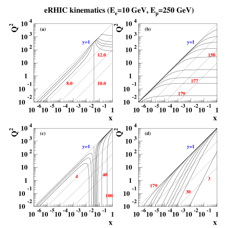
Figure 1 shows isolines of constant electron energy (a) and scattering angle (b) as well as lines of constant values (1, 0.1, 0.01, 0.001). The kinematic variable is given in terms of and () and refers to the inelasticity in the rest frame of the proton. The kinematic limit is given by . The scattering angle is measured with respect to the incoming proton beam which defines the positive axis. Electron tagging acceptance down to at least will be necessary to provide acceptance in down to GeV2. The energy of the scattered electron is less than GeV for a large fraction of the kinematic region and is in particular small in the region of low and medium to low values in . This sets stringent requirements on trigger and reconstruction efficienies. Figure 1 shows isolines of constant current jet energy (c) and scattering angle (d). The energy of the current jet is rather small in the low and medium to low region and overlaps to some extend with the scattered electron. This will require e/h separation in particular in the rear direction, i.e. the direction of larger electron scattering angles with respect to the incoming proton beam. The current jet energy increases towards the forward direction in the region of high and values. The capability to measure larger jet energies will be in partiuclar important in the forward direction, i.e. the incoming proton beam direction.
The following minimal requirements on a future eRHIC detector can be made:
Measure precisely the energy and angle of the scattered electron (Kinematics of DIS reaction)
Measure hadronic final state (Kinematics of DIS reaction, jet studies, flavor tagging, fragmentation studies, particle ID)
Missing transvere energy measurement (Events involving neutrinos in the final state, electro-weak physics)
In addition to those demands on a central detector, the following forward and rear detector systems are crucial:
Zero-degree photon detector to control radiative corrections and measure Bremsstrahlung photons for luminosity measurements
Tag electrons under small angles (Study of the non-perturbative/perturbative QCD transition region and luminosity measurements from Bremsstrahlung ep events)
Tagging of forward particles (Diffraction and nuclear fragments)
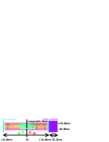
Optimizing all the above requirements is a challenging task. Two detector concepts have been considered so far. One, which focuses on the forward acceptance and thus on low-/high- physics which emerges out of HERA-III detector studies [5]. This detector concept is based on a compact system of tracking and central electromagnetic calorimetry inside a magnetic dipole field and calorimetric end-walls outside. Forward produced charged particles are bent into the detector volume which extends the rapidity coverage compared to existing detectors. A side view of the detector arrangment is shown in Figure 2. The required machine element-free region amounts to roughly m. This clearly limits the achieveable luminosity in a ring-ring configuration.
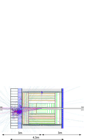
The second design effort focuses on a wide acceptance detector system similar to the current HERA collider experiments H1 and ZEUS to allow for the maximum possible range. The physics program demands high luminosity and thus focusing machine elements in a ring-ring configuration which are as close as possible to the interaction region while preserving good central detector acceptance. This will be discussed in more detail in the next section. A simulation and reconstruction package called ELECTRA has been developed to design a new eRHIC detector at BNL [4]. Figure 3 shows a side view of a GEANT detector implementation of the above requirements on a central detector. The hermetic inner and outer tracking system including the electromagnetic section of the barrel calorimeter is surrounded by an axial magnetic field. The forward calorimeter is subdivided into hadronic and electromagnetic sections based on a conventional lead-scintillator type. The rear and barrel electromagnetic consists of segmented towers, e.g. a tungsten-silicon type. This would allow a fairly compact configuration. Other options based on a crystal rear and barrel electromagnetic calorimeter are under study. The inner most double functioning dipole and quadrupole magnets are located at a distance of m from the interaction region. An initial interaction region design assumed those inner most machine elements at m. This would significantly impact the detector acceptance and is therefore not considered. More details on the interaction region design can be found in [1].
The bunch crossing frequency amounts to roughly MHz. This sets stringent requirements on the high-rate capabililty of the tracking system. This makes a silicon-type detector for the inner tracking system (forward and rear silicon disks together with several silicon barrel layers) together with several GEM-type outer tracking layers a potential choice. The forward and rear detector systems have not been considered so far. The design and location of those detector systems has to be worked out in close collaboration to accelerator physicists since machine magnets will be potentially employed as sepectrometer magnetes and thus determine the actual detector acceptance and ultimately the final location. It is understood that demands on optimizing the rear/forward detector acceptance might have consequences on the machine layout and is therefore an iterative process.
3 Considerations on the detector/machine interface
The following section provides an overview of some aspects of the detector/machine interface. The specification of those items has only recently been started:
3.1 Synchrotron radiation
The direct synchrotron radiation has to pass through the entire interaction region before hitting a rear absorber system. This requires that the geometry of the beam pipe is designed appropriately with changing shape along the longitudinal beam direction which includes besides a simulation of the mechanical stress also the simulation of a cooling system of the inner beam pipe. The beam pipe design has to include in addidition the requirement to maximize the detector acceptance in the rear and forward direction. Furthermore the amount of dead material has to be minimized in particular to limit multiple scattering (track reconstruction) and energy loss for particles under shallow angles (energy reconstruction). The distribution of backscattered synchrotron radiation into the acutal detector volume has to be carefully evaluated. An installation of a collimator system has to be worked out. Those items have been started in close contact to previous experience at HERA [6].
3.2 Location of inner machine elements
The demand of a high luminosity ep/eA collider facility requires the installaton of focusing machine elements as close as possible to the central detector. An interaction region design with machine elements as close m to the interaction region which has been presented in [1] would significantly limit the achievable detector acceptance. A new scheme has been presented in [2] which provides a machine-element free region of m at the expense of approximatley half the luminosity for the interaction region design presented in [1]. A linac-ring option would not be limited by beam-beam effects compared to a ring-ring configuration. Even larger luminosities could be achieved with a machine-element free region of approximatley m. This scheme has been presented in [7].
3.3 Rear tagging system
The need for acceptance of scattered electrons beyond the central detector acceptance is driven by the need for luminosity measurements through ep/eA Bremstrahlung and photo-production physics. Besides that a calorimeter setup to tag radiated photons from inital-state radiation and Bremsstrahlung will be necessary. The scattered electrons will pass through the machine elements and leave the beam pipe through special exist windows. The simulation of various small-angle calorimeter setups has been started. This will require a close collaboration with the eRHIC machine design efforts to aim for an optimal detector setup.
3.4 Forward tagging system
The forward tagging system beyond the central detector will play a crucial role in diffractive ep/eA physics. The design of a forward tagger system based on forward calorimetry and Roman pot stations is foreseen. Charged particles will be deflected by forward machine elements. This effort will require as well a close collaboration with the eRHIC machine design efforts to ensure the best possible forward detector acceptance.
References
- [1] http://www.agsrhichome.bnl.gov/eRHIC/.
- [2] C. Montag, B. Parker, S. Tepikian and D. Wang, these proceedings.
- [3] B. Surrow, EPJdirect C2 (1999) 1.
- [4] J. Pasukonis and B. Surrow, http://starmac.lns.mit.edu/∼erhic/electra/.
- [5] I. Abt, A. Caldwell, X. Liu and J. Sutiak, hep-ex/0407053.
- [6] J. Beebe-Wang, A. Desphpande, C. Montag, D. Rondeau, B. Surrow, these proceedings.
- [7] V. Litvinenko, these proceedings.