Correlation of Beam Electron and LED Signal Losses under Irradiation and Long-term Recovery of Lead Tungstate Crystals
Abstract
Radiation damage in lead tungstate crystals reduces their transparency. The calibration that relates the amount of light detected in such crystals to incident energy of photons or electrons is of paramount importance to maintaining the energy resolution the detection system. We report on tests of lead tungstate crystals, read out by photomultiplier tubes, exposed to irradiation by monoenergetic electron or pion beams. The beam electrons themselves were used to measure the scintillation light output, and a blue light emitting diode (LED) was used to track variations of crystals transparency. We report on the correlation of the LED measurement with radiation damage by the beams and also show that it can accurately monitor the crystals recovery from such damage.
keywords:
Scintillating crystal , lead tungstate , energy calibrationPACS:
61.80.-x , 29.40.Vj, , , , , , , , , , , , , , , , , , , , ††thanks: corresponding author, email: ryazantsev@mx.ihep.su , , , , , , , ,
1 Introduction
Electromagnetic calorimeters built of the lead tungstate (PbWO4, PWO) scintillating crystals will be used in several high energy physics experiments, such as ALICE and CMS at the CERN LHC [1, 2, 3]. This work was done for studies of the electromagnetic calorimeter for BTeV at the FNAL Tevatron Collider [4]. Unfortunately, BTeV was terminated by the U.S. Dept. of Energy.
Over the last several years, the PWO crystals have been extensively studied at the Institute for High Energy Physics (IHEP) in Protvino, Russia [5, 6, 7, 8, 9, 10]. In particular, the studies confirmed that the PWO light output degrades under irradiation by high-energy electron or pion beam of high intensity. The light loss has a tendency to exhibit saturation when the dose rate is kept at a constant level. On the other hand, the light output changes whenever the radiation rate changes. Thus, they have to be monitored continuously during operation to maintain excellent energy and space resolutions of the calorimeter.
Monte-Carlo study indicates that there would be enough electrons and positrons from photon conversion near the interaction region and semileptonic decays to calibrate the detector in-situ. The rates of collecting electrons/positrons for the calibration vary in different areas of the calorimeter, ranging from less than 1 hour to about several hours of data taking to achieve the calibration accuracy of . Any changes in the crystal light output over this time scale must be monitored using the transparency measurements. On the other hand, the transparency monitoring does not have to be stable over much longer time scale like a month since the electron calibration takes care of that part.
We presume that the PWO light output degradation is caused by the changes in the transparency since no evidence of the scintillating mechanism damage has been found so far [11]. Thus, a highly stable reference light pulser sending light through the crystal can be used to measure the transparency changes and predict the scintillation light output changes from the PWO crystals.
When the coefficient of light absorption changes by , the light transmission changes by a factor of , where is the path length that light must travel from the source to the light detector. It is expected that for several hours of data taking, and it is relevant to use a linear approximation. Therefore the fractional loss is given by . Considering that the path lengths for scintillation and monitoring light are different, the fractional losses for the two processes will be different, but are expected to be proportional.
The dose rate profiles induced by electron and pion beams are significantly different longitudinaly [8]. This could potentially lead to different proportionality constants for electron or pion irradiation. Our studies addressed those issues for different crystals and under different conditions. A dedicated test beam run took place at the IHEP-Protvino test beam facility [6] in November-December 2002.
Irradiation of PWO crystals has been done using high-intensity 34 GeV pion beam and 23 GeV electron beam. Following the run, the crystals were left for a long-term natural recovery for over a 3-months period. Their light transmittance changes were measured with the LED monitoring system [9]. Results are presented in this paper.
2 Test beam apparatus and irradiation procedure
The IHEP-Protvino test beam facility is described in details in [7]. The major components are momentum tagging system and a prototype of the PWO crystal calorimeter. The prototype is a 55 matrix of crystals from two vendors, Bogoroditsk and Shanghai, and is installed in a thermo-stabilized light-tight box on a moving platform. All the crystals are rectangular in shape, with a 2727 mm2 cross-section and a 220 mm length. They were instrumented with 6-stage R5380Q Hamamatsu photomultiplier tubes (PMT).
Before irradiation, scintillation light output of the crystals was measured with the use of a low intensity electron beam. All results presented in this paper are normalized to the results of this very first calibration.
All crystals received from 500 rad to 1.5 krad of integral dose over the entire studies. During the electron irradiation runs, position of the electron peak itself was used to monitor the light output continuously. During the irradiation by pions, data taking runs alternated with calibration runs by low intensity electron beam, to monitor changes in the crystals light output. For the pulse height analysis, only electrons that hit the central part (22 mm2) of the crystal’s front face were selected using the data from drift chambers.
Light transmittance change in the crystals was measured continuously with the use of a blue (470 nm) LED. Optical fibers guided light from the LED to the front side (opposite from the end where the PMT was attached) of the crystals. The typical path length of LED light in the crystal approximately equals the length of the crystal. The light comes out of the optical fiber with a characteristic full angle spread of 25∘; this angle is reduced to 11∘ as the light enters the crystal from air. Thus, the path length of the light in a crystal should be increased by , i.e. order of 2%. As for the scintillation light from incident particles, taking into account that this light is emitted isotropically and the crystal is wrapped with Tyvek (diffuse reflecting material), its average path length to the photocathode is longer due to the multiple reflections. In addition, the LED system monitors the transparency of the crystal at a specific wavelength (in our case, 470 nm was chosen partially due to the availability of blue LEDs) and thus does not sample the entire spectrum of scintillation light. The radiation damage effect is less severe at 470 nm than at 430 nm, which is the center of the PWO scintillation emission peak. From these considerations, we expect that the ratio, , of the light loss factors for the LED signal and the particle signal should be less than 1.
3 Experimental results
3.1 Data from calibration runs
The mean pulse heights of the scintillation signal and of the LED signal were obtained using the data from the calibration runs and normalized to the results of the very first calibration. Fig. 1 shows an example of the correlation between the relative changes of the LED signal vs. relative changes of the scintillation signal. Points 1–4 represent measurements taken during the pion irradiation period; they fit very well to a linear function. Points 5–6 were taken when the crystal started to recover. By this we mean that the high intensity pion beam moved away from this crystal and onto other crystals, thus the dose rate on the spot decreased significantly and the light output started to restore, as was measured in the subsequent calibration runs. It has to be noted that points 5–6 agree very well with the same linear fit applied to the data taken during the irradiation period. The fit function is shown below:
| (1) |
where and are relative electron and LED signals, respectively. For this particular crystal, the proportionality coefficient was obtained to be with an accuracy of .

The same calculations were applied for all the crystals that have been irradiated either by electrons or pions. Distributions of the coefficients obtained from a linear fit of the LED vs. electron dependencies for each crystal are presented in Fig. 2 for (a) pion and (b) electron irradiation. The mean values of the two distributions are the same within errors.

3.2 Continuous electron calibration
All electrons incident within 33 array of the crystals and satisfying the condition, that the energy deposit over 9 crystals in this array was within of the beam energy, were selected for this analysis. The electron irradiation data were subdivided into smaller data sets, each set corresponded to 15 min of data taking. The mean signals for the 9 crystals in the array were calculated for each of the subsets. A standard inverse matrix iteration procedure of crystal calibration required not more than 6 iterations.
Fig. 3(a) shows the electron signal and the blue LED signal vs. time for one of the crystals during the electron irradiation period when the average dose rate was 20 rad/h; both signals have been normalized to the light output measured at the beginning of the irradiation period. Fig. 3(b) shows the correlation between relative electron signal and relative blue LED signal. The linear fit coefficient is computed with much better accuracy of than in the case of discrete calibration runs in the pion irradiation data.

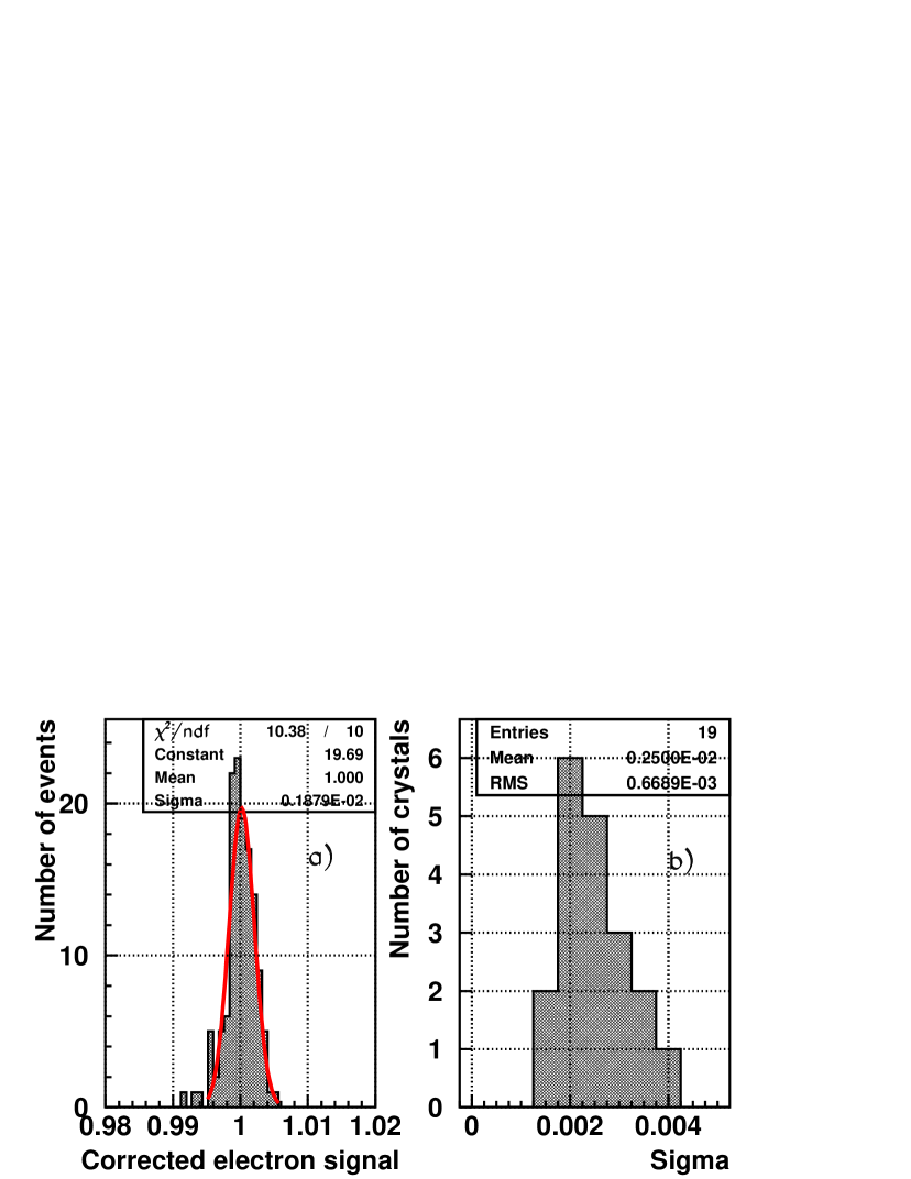
Fig. 4 demonstrates how accurate the energy correction can be in a single crystal with the use of a stable light calibration source if the coefficient in formula 1 is known. The results presented here were obtained over 35 hours of data taking. While the response changed over each 15-minutes period, the effect was corrected according to the change in the LED signal and with the knowledge of the linear fit coefficient that is shown in Fig. 3(a). The corrected energy distribution fitted by Gaussian has equal to 0.2%. Fig. 4(b) shows the distribution of Gaussian computed for 19 crystals with mean at 0.25% and r.m.s. about 0.07%.
4 Long time crystals recovery
We observed that the transparency of the crystals recovered upwards to its level before irradiation. Light output from the crystals was constantly monitored with the blue LED during for more than 3 months. Fig. 5 shows typical recovery process for one of the crystals. This crystal was irradiated with the dose rates which varied from 15 to 30 rad/h and accumulated 2.2 krad absorbed dose.
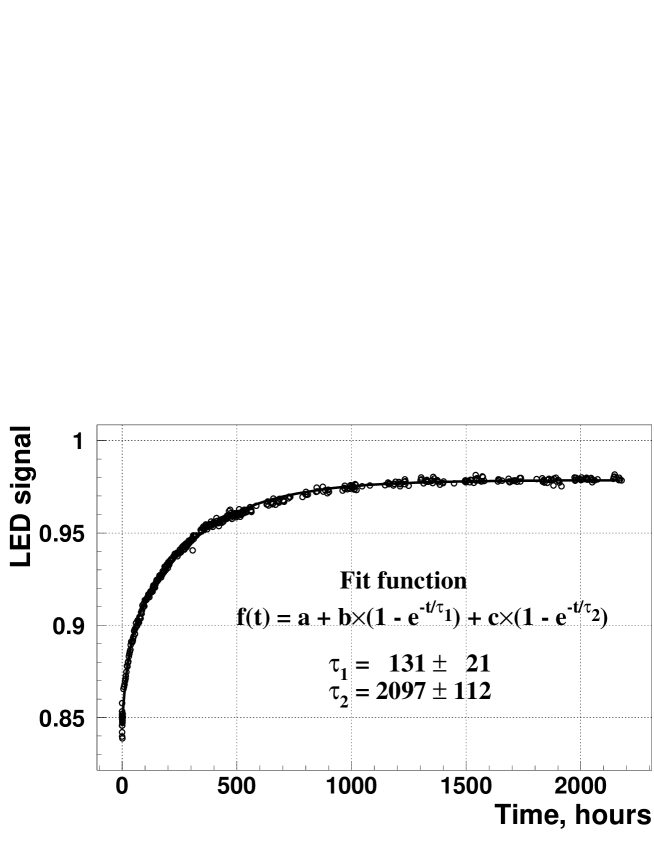
The experimental results were fitted with function:
| (2) |
Besides continuous monitoring of the changes in the crystals light transmittance with the LED, at the end of the recovery period of more than 2200 hours, a calibration run with a low intensity electron beam was taken. The results of the calibration run were compared to those from the crystals calibration at the end of the irradiation run. Fig. 6 shows that on average the light output from the crystals degraded to 86% of its initial level at the end of the irradiation run but naturally recovered up to 98%.

5 Conclusions
The goal of this study was to confirm that the electromagnetic calorimeter made of lead tungstate crystals read out by photomultiplier tubes can be continuously calibrated to the required accuracy with the use of LED-based monitoring system within a period of 1 day or shorter.
We studied crystals behaviour under electron or hadron irradiation and whether the changes in their responses to electrons would scale well with their response to the blue LED.
We found that the relative changes of the LED and electron signals can be approximated by a linear function in both the electron and pion irradiation studies. The obtained linear fit coefficients are consistent with each other. This strongly suggests that in the real experimental environment, where the crystals will be irradiated by a mixture of hadrons, gammas and electrons, linear fit will be sufficient for the calorimeter’s calibration.
When the electron data were corrected for the transmission loss, which is due to irradiation, using the LED data, the corrected energy measurements are constant to within . This satisfies one of the most important technical requirements of modern experiments.
Over the 3-months long recovery period that followed the irradiation run we found that the light output of the crystals restored from an average of 86% to 98%. It was also found that, for a given crystal, correlations between electron signal and blue LED signal are linear and are the same if measured during irradiation or during the recovery period.
6 Acknowledgements
This work was supported by the U.S. National Science Foundation and the Department of Energy as well as the Russian Foundation for Basic Research grant 02-02-39008.
References
- [1] A.A. Annenkov, et al., Nucl. Instr. and Meth. A490(2002) 30.
- [2] ALICE Collaboration, Technical Proposal, CERN/LHCC/95-71, Geneva, 1995.
- [3] CMS Collaboration, The Electromagnetic Calorimeter Project Technical Design Report, CERN/LHCC 97-33, CMS TDR 4 (1997).
-
[4]
A. Kulyavtsev, et al., Proposal for an Experiment
to Measure Mixing, CP Violation and Rare Decays in Charm and
Beauty Particle Decays at the Fermilab Collider - BTeV, May 2000;
G.Y. Drobychev, et al., Update to Proposal for an Experiment to Measure Mixing, CP Violation and Rare Decays in Charm and Beauty Particle Decays at the Fermilab Collider - BTeV, March 2002. - [5] T. Brennan, et al., Nucl. Instr. and Meth. A494 (2002) 313.
- [6] V.A. Batarin, et al., Nucl. Instr. and Meth. A510 (2003) 211 (e-Print ArXiv hep-ex/0208012).
- [7] V.A. Batarin, et al., Nucl. Instr. and Meth. A510 (2003) 248 (e-Print ArXiv hep-ex/0209055).
- [8] V.A. Batarin, et al., Nucl. Instr. and Meth. A512 (2003) 484 (e-Print ArXiv hep-ex/0210011).
- [9] V.A. Batarin, et al., Nucl. Instr. and Meth. A534 (2004) 486 (e-Print ArXiv physics/0311119).
- [10] V.A. Batarin, et al., Nucl. Instr. and Meth. A530 (2004) 286 (e-Print ArXiv physics/0312063).
- [11] V.A. Batarin, et al., Nucl. Instr. and Meth. A540 (2005) 131 (e-Print ArXiv physics/0410133).