Strongly coupled large-angle stimulated Raman scattering of short laser pulse in plasma-filled capillary
Abstract
Strongly coupled large-angle stimulated Raman scattering (LA SRS) of a short intense laser pulse develops in a plane plasma-filled capillary differently than in a plasma with open boundaries. Coupling the laser pulse to a capillary seeds the LA SRS in the forward direction (scattering angle smaller than ) and can thus produce a high instability level in the vicinity of the entrance plane. In addition, oblique mirror reflections off capillary walls partly suppress the lateral convection of scattered radiation and increase the growth rate of the SRS under arbitrary (not too small) angle. Hence, the saturated convective gain falls with an angle much slower than in an unbounded plasma and even for the near-forward SRS can be close to that of the direct backscatter. At a large distance, the LA SRS evolution in the interior of the capillary is dominated by quasi-one-dimensional leaky modes, whose damping is related to the leakage of scattered radiation through the walls.
pacs:
52.35 Mw, 52.38 Bv, 52.40 FdI Introduction
The technique of chirped-pulse amplification Mourou made sub-picosecond laser pulses of high power ( W) available for generation of coherent x-rays Burnett , high harmonics of radiation Lompre , and laser wakefield acceleration (LWFA) of electrons Tajima ; Mora ; Esarey_IEEE in rarefied plasmas [where , is a laser frequency, is an electron plasma frequency, is a background electron density, and are the electron mass at rest and charge]. Full potential of these applications can be realized with the laser-plasma interaction length increased beyond the Rayleigh diffraction length, , by means of external optical guiding Esarey_IEEE (here and later, is a laser wavelength, and is a laser beam waist radius). In particular, a dielectric capillary, where the oblique mirror reflections suppress the laser beam diffraction, can be used as a guiding tool Marcatili ; Andreev ; Capillary_vacuum . Plasma can be created in a capillary by an optical field ionization of the filling gas Capillary_plasma ; CrosPScr ; Andreev_capillary , or by a laser ablation of the walls Kitagawa . Then, the large-angle stimulated Raman scattering (LA SRS) starts to challenge the transportation of a laser beam over a long distance McKinstrie3 ; CourtoisDiss .
In the standard SRS process Andreev0 , the pump electromagnetic wave (EMW) is scattered off spontaneous fluctuations of electron density, which, in turn, can be amplified by the ponderomotive beat wave of pump and scattered light. Appropriate phase matching of the waves results in a positive feedback loop with the onset of a spatio-temporal instability Forslund . When the plasma extent is much larger than a laser pulse length, and no reflections off plasma boundaries occur, both scattering electron plasma waves (EPW) and scattered EMW quit the region of amplification, and the convective gain saturates within a time interval of the order of pulse duration Mora0 ; McKinstrie1 ; Kalmykov_multi ; Kalmykov . Given the pulse length, the maximum possible gain remains the same for all scattering angles, and whether it is achieved or not for a given angle is determined by the laser pulse aspect ratio only Mora0 ; McKinstrie1 ; Kalmykov_multi ; Kalmykov . Convection of scattered radiation out of the laser waist may result in a strong pulse depletion Rousseaux . Even when the full depletion does not occur, the LA SRS can produce considerable pulse erosion ErrDep , suppression of the relativistic self-focusing Tzeng , heating and pre-acceleration of plasma electrons Kruer , and seeding the forward SRS Sakharov ; Hafizi . Thereby, knowing the details of the LA SRS evolution in various physical conditions is a matter of high importance for applications.
Confining plasma between reflecting surfaces deeply modifies the SRS process. In the one-dimensional (1D) geometry, the Raman backscatter changes its nature from convective to absolute Bobroff : reflections trap the unstable radiation modes inside plasma and give rise to the continuous amplification. When the laser beam is confined between the mirror-reflecting partly transparent walls, and propagates collinearly to them, reflections reduce the sideward convection of scattered light. If the reflective modes dominate in plasma, the LA SRS gain tends to that of the direct backscatter and thus reveals a dramatic increase in comparison with the open-boundary system McKinstrie3 . The LA SRS in this geometry has been considered so far in the regime of weak coupling McKinstrie3 , when the scattering EPW is similar to the plasma natural mode Forslund , and temporal growth rate is well below the electron plasma frequency. This regime requires fairly low amplitude of a laser pulse, i.e., [ is a normalized amplitude of the laser electric field]. However, for the efficient LWFA Tajima ; Mora ; Esarey_IEEE , the plasma density have to be reduced in order to increase the gamma-factor of the laser wakefield, , and, hence, the electron energy gain. With , the LA SRS becomes strongly coupled: its temporal growth rate exceeds , and the scattering EPW differs from the natural mode of plasma oscillations Mora0 ; Kalmykov ; Sakharov ; Darrow ; MounaixSC . In a plasma-filled capillary, the strongly coupled LA SRS acquires new specific features: in a wide range of parameters relevant to the self-modulated LWFA Mora , our PIC simulations (using the code WAKE Mora1 ) discovered a vast enhancement of the near-forward SRS in the immediate vicinity of the capillary entrance aperture. The unstable plasma modes were primarily transverse and therefore useless for the longitudinal electron acceleration. For the same range of parameters, this effect has never been significant in an open-boundary plasma. Independent fluid modelling AndreevPrComm verified these observations.
Making a step to understanding this phenomenon we propose a two-dimensional (2D) linear theory of strongly coupled SRS of a short laser pulse under a given angle in a slab of rarefied plasma laterally confined between the mirror-reflecting partly transparent flat walls (flat capillary). Boundary conditions for the scattered radiation describe the oblique mirror reflections and the electromagnetic (EM) seed at the entrance plane. We associate the latter with the signal formed of the high-order capillary eigenmodes produced by the laser beam coupling to the capillary (the coupling process is described elsewhere Andreev ; CrosPScr and is outlined in Appendix A). SRS in forward () and backward () direction proceed differently. Forward Raman amplification of the EM seed can be dominant within a finite distance from the entrance plane and be responsible for the instability enhancement observed in the modelling. On the other hand, the backward SRS is affected by the reflections only. As the LA SRS of a finite-length laser pulse preserves the convective nature (backward and, partly, sideward convection of radiation is allowed), the gain saturation occurs within a finite distance from the entrance plane. Reflections give the unstable modes additional rise time in any transverse cross-section of a plasma, and, even for relatively small scattering angles (such as taken for numerical examples of this paper), the saturated convective gain can approach that of the backward SRS (BSRS). The field structure is then approximated by a quasi-1D lossy mode whose damping is produced by the leakage of radiation through the walls.
The paper is organized as follows. Section II presents a theoretical model of the strongly coupled LA SRS in a 2D slab geometry. The laser pulse entrance into a plasma and oblique mirror reflections of scattered light are expressed in terms of appropriate boundary-value conditions for the coupled-mode equations. General solution of the boundary-value problem is presented (derivation is given in Appendix B). Section III discusses the spatio-temporal evolution of instability. The case of fully transparent lateral boundaries is considered in subsection III.1. Enhancement of the LA SRS in the generic reflective case is considered, and the maximum gain factors are evaluated in terms of appropriate asymptotic solutions in subsection III.2. Section IV summarizes the results.
II Basic equations and solution of boundary-value problem
In a 2D plasma slab confined between mirror-reflecting capillary walls, the high-frequency (hf) electric field is a superposition
| (1) | |||||
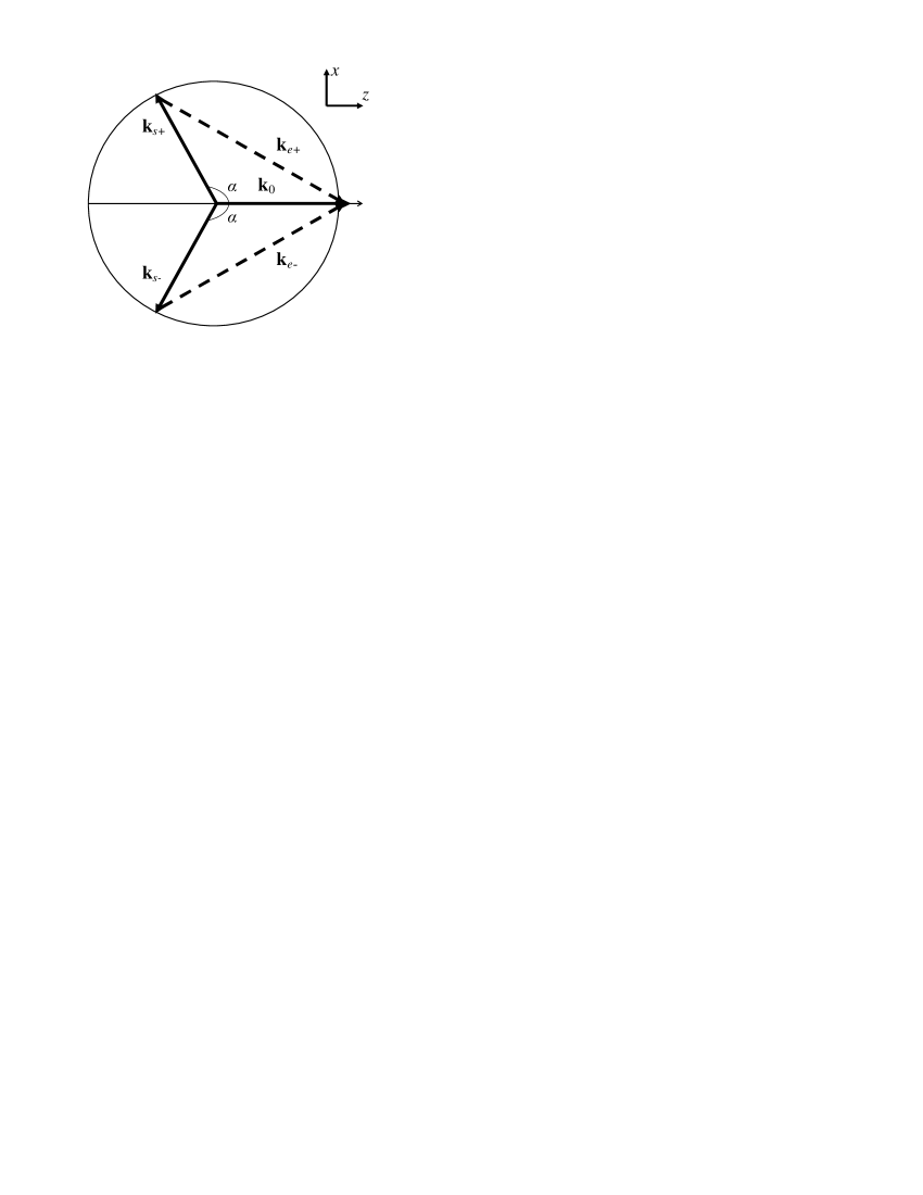
of that of the laser, , and of up- and down-going scattered EMWs, (); in Eq. (1) and below, is a radius-vector in a plane geometry. We assume that the waves (1) have the linear polarization with the electric vectors parallel to the walls, and that the scattering occurs under an angle in the plane orthogonal to the polarization vector. In the rarefied plasma, both and obey the same dispersion relation ; hence, , , , and the amplitudes vary slowly in time and space on the scales , , and . Ions form a homogeneous positive background; this assumption holds for a laser pulse shorter than an ion plasma period, . The beat wave of incident and scattered radiation excites perturbations of electron density,
| (2) |
whose wave vectors obey the matching conditions ; hence, , , . Wave vector diagram of the LA SRS is shown in Fig. 1. The scattering EPW has a longitudinal component of phase velocity small compared to the speed of light, i.e., . This restriction eliminates the forward Raman scattering Sakharov ; Turano and resonant modulational instability (RMI) RMI . In the rarefied plasma, the amplitudes vary slowly in space on the scales , .
The amplitudes of up- and down-going scattered EMW and scattering EPW obey the coupled-mode equations derived from the equations of non-relativistic hydrodynamics of cold electron fluid in the hf field (1) and Maxwell’s equations for the scattered radiation,
| (3a) | |||||
| (3b) | |||||
where , , , and . The wave coupling parameter is (strong coupling is the case for ). Equations (3) are expressed through the variables , , and , that is, the temporal evolution of waves is traced in an cross-section at a longitudinal position .
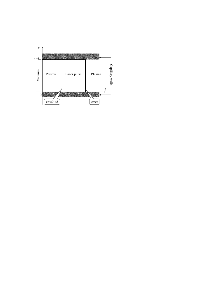
Figure 2 shows the interaction area. At , , the laser pulse enters a semi-infinite plasma-filled gap between flat mirror-reflecting walls (, ) and propagates towards positive . The pulse leading front, , encounters the stationary level of electron density perturbations with a constant amplitude ,
| (4a) | |||||
| (4b) | |||||
fluctuations of radiation in fresh plasma being neglected,
| (5) |
At the capillary entrance plane, the transverse profile of radiation can have a significant content of the high-order capillary eigenmodes (coupling the incident laser beam to the capillary is discussed elsewhere Andreev ; CrosPScr and is outlined in Appendix A). The resonant condition for the wave vectors selects the modes that can be amplified by the forward SRS () thus leading to the formation of an EM seed signal. To facilitate the forthcoming analytic job, we give this signal in a simple parabolic form with an amplitude vanishing at the walls in order to provide the continuity of the solution in the interior of the capillary,
| (6) |
Inside the capillary, oblique mirror reflections couple up- and down-going EMW: each reflection converts an up-going wave into a down-going one and vice versa,
| (7a) | |||||
| (7b) | |||||
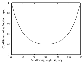
The conditions (7) set up a quasi-1D exponential behavior of waves at large . The reflectivity coefficient is a known function of scattering angle, , where and are the refraction indexes of walls and plasma. Figure 3 shows for a glass capillary with and .
The temporal increment of strongly coupled LA SRS exceeds the electron plasma frequency. Hence, we neglect in comparison with in the left-hand side (LHS) of Eq. (3b). With the allowance for not very tight capillary, the pump field envelope represents a portion of laser radiation coupled to the capillary which experiences mostly paraxial propagation, . Assuming that the pump field evolution at a given point takes much longer than the SRS growth (), and in order to enable the analytic progress, we approximate with a fixed flat profile at any position in a capillary of the width , , using the effective pulse duration and amplitude . Here and below, is the Heaviside step-function. Solution of the boundary-value problem,
| (8a) | |||||
| (8b) | |||||
is then obtained via the 2D Laplace transform; here, , , , is the regularized generalized hypergeometric function IncGamma ,
| (9a) | |||||
| (9b) | |||||
| (9c) | |||||
where , and the fundamental solution (Ref. Kalmykov, ) is defined by Eq. (24). The up- and down-going amplitudes are symmetric, , , so we consider below the evolution up-going waves only. Our solution possesses the same generic structure as the weakly coupled reflective solution discussed in detail in Ref. McKinstrie3, . However, contrary to the case of semi-infinite laser pulse of Ref. McKinstrie3, , the growth time of unstable waves is now limited by the pulse duration , and, as shown in the subsection III.2, the gain at a given point remains finite and is given by either Eq. (15) or (16).
III Spatio-temporal evolution of unstable waves
III.1 Evolution of instability in open-boundary system
When the lateral boundaries are fully transparent, , the EM seed at the entrance plane vanishes (), and the instability grows from the electron density noise in a fresh plasma ahead of the pulse. The functions (9) then read
Plasma is divided by the characteristics , , , into ranges of dependence, where the solution is prescribed by the boundary conditions for radiation posed at the pulse leading edge (range I),
| (10) |
at the wall (range II),
| (11) |
or at the entrance plane (range III),
| (12) |
The principal feature that makes the LA SRS of a short pulse Kalmykov different from the case of semi-infinite laser beam McKinstrie1 is the gain saturation within a finite distance from the entrance plane. At some point, , the scattered radiation arriving from the plasma boundary drops behind the laser pulse, and in all the points neither part of the pulse belongs to the range III. Then, the evolution of waves and the gain do not alter with . The gain saturates differently for the forward () and backward () scattering.
When , and the distance from the entrance plane is not too large, i.e., , all the three areas (10)-(12) are available in the pulse body (that is, within a rectangle , ). Given the point , waves fall initially within a range I, where they grow in time exponentially with an angle-independent increment
| (13) |
Note, that is the known “spatial” increment of the strongly coupled BSRS in the co-moving frame Esarey_IEEE ; Mora0 ; Kalmykov_multi ; Kalmykov ; Sakharov ; MounaixSC . The evolution of waves is strictly 1D in space on this stage. Later, information from the boundaries and reaches the point , and the spatial dependence becomes either 2D for , (range II) or remains 1D for , (range III). The waves are not exponentially growing at this time. In the range III, the entrance effect dominates: vanishing the scattered EMW at the boundary determines the behavior of 1D amplitudes. Deeply enough in plasma, , the entrance effect vanishes as the pulse terminates sooner than the scattered EMW from the entrance plane can reach the observer at a given . The pulse body is then divided between the ranges I and II, and the evolution of LA SRS is the same through the rest of the plasma.
For , the boundary-value condition posed for radiation at can only produce the scattered EMW convecting outwards (the EMW characteristic recasts in the lab frame variables as , and corresponds to the wave propagating towards negative ). Thus, the entrance effect does not change the solution at a positive , and the boundary-value condition (6) becomes excessive (this is also valid in the reflective case). The spatio-temporal evolution of the LA SRS remains the same at any .
Given the pulse duration, the maximum of the saturated gain, , does not depend on the scattering angle, and whether it is achieved or not is determined solely by the pulse aspect ratio Kalmykov . If the pulse is wide, or the scattering angle is sufficiently large, , the maximum gain is achieved at the pulse rear edge for . Hence, the angular spectrum of scattered light is prescribed by the pulse aspect ratio rather than the angular dependence of the increment. For , scattering within a broad range of angles proceeds with the maximum gain. Otherwise, for , the highest gain corresponds to the near-backward scattering only, (Ref. Kalmykov, ). To estimate the pulse energy depletion due to the LA SRS, it is sufficient to neglect the radiation scattered under angles smaller than (Ref. Kalmykov_d, ).
III.2 LA SRS evolution in the reflective case
In a capillary, the oblique mirror reflections of scattered light off the walls [the boundary condition (7)] contribute to the LA SRS evolution over the whole laser path in plasma, but become actually dominating later, when the entrance effect vanishes (). The reflections establish a long-distance asymptotic state of the LA SRS — amplification of a quasi-1D radiation and plasma modes with a temporal increment close to that of the direct backscatter (13). Besides, the forward SRS is seeded by the EM signal at the capillary entrance plane [the boundary condition (6)]. If the signal amplitude exceeds the amplitude of the electron density noise , the unstable waves will achieve a large amplitude (by virtue of the high seed level) at the transient stage of laser propagation, . In this case, contrary to the SRS in the unbounded plasmas described in the preceding subsection, the near-forward SRS exhibits much higher level of amplification than the backward SRS (), and its contribution to the dynamics of electron density perturbations can be dominating. Nonlinearities of plasma response that can then appear are worth investigating and will be addressed in future publications.
The asymptotic at (Ref. IncGamma, ) helps to evaluate the level of the EM seed amplification within the interval ,
| (14) |
where . Then, . At the pulse trailing edge, , the argument of the asymptotic reaches the maximum at . The EPW amplitude at this point is
| (15) |
and . Equation (15) shows that the maximum gain on the transient stage is determined by the 1D temporal increment (13) independent on (the angular dependence is retained in the pre-exponential factors only). For the minimally allowed scattering angle, (hence, ), the point of the maximal gain is . Parameters of the following numerical example (Fig. 4) give mm, which is shorter than a typical capillary length used in experiments ( cm) Andreev ; Capillary_vacuum ; Capillary_plasma ; CrosPScr ; Andreev_capillary ; Kitagawa ; CourtoisDiss .
For , the entrance effect becomes less pronounced and finally vanishes at the point , where the EM signal arriving from drops behind the laser pulse, and the instability growth saturates. Evolution of both forward and backward scattering is then determined by the lateral reflections only and, given the scattering angle, remains the same in any cross-section for . We show in Appendix C that at , and , a cumbersome exact solution (8a) tends asymptotically to a quasi-1D damped mode with a temporal growth rate close to (13) that gives the asymptote for the density perturbation amplitude,
| (16) |
Here, , . Equation (16) is valid under the “low leakage” condition, , which indicates that the scattered light is mostly trapped inside a plasma slab: the energy leakage through the wall at one reflection (that produces an effective decrement ) is less than the energy gain on the way between the walls. The lateral growth of the asymptote (16) is much slower than the growth with . Asymptotic solution (16) displays the basic result of the reflective theory of the LA SRS: at large distances from the entrance plane and large coefficients of amplification, the amplitudes of unstable waves tend to quasi-1D leaky modes exponentially growing in time with the increment tending to that of the BSRS (13).
Comparison of Eqs. (15) and (16) shows that the maximum amplitude of the scattering EPW on the transient stage, , differs from the final asymptotic level of density perturbations roughly by a factor of . When this factor is larger than unity, and , the plasma response can become nonlinear in the vicinity of . This could be avoided by keeping the ratio of the seed amplitudes below . The amplitude of the electron density noise is difficult to control in experiment; however, as shown in Appendix A, the content of the high-order eigenmodes in the laser radiation coupled to the capillary (and, hence, the amplitude of the EM seed signal), can be effectively reduced by increasing the capillary radius versus the radius of the incident laser beam.
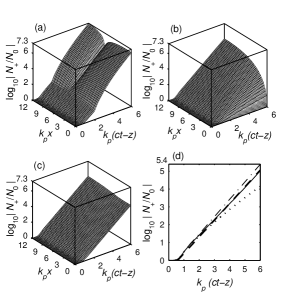
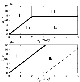
Figure 4 shows the spatio-temporal evolution of an up-going EPW [Eq. (8b)] for the SRS under the angle . The laser and plasma parameters are , m, , , which give cm-3, the pulse duration fs, and the maximum increment . The level of EM seed is chosen (according to Appendix A, it corresponds to a capillary by a factor of two wider than in the case of perfect matching; by the definition, in axi-symmetric geometry, the perfect matching condition provides coupling 98% of energy of an incident Gaussian laser pulse to the fundamental eigenmode EH11 of a capillary Andreev ). The level of the plasma noise evaluated in Appendix A is . The plots (a) and (c) correspond to the plasma confined in a glass capillary with the reflection coefficient (see Fig. 3), and (b) — to the unbound plasma ( and ); plot (d) shows the long-term asymptotic behavior of the reflective solution. The plasma cross-sections are set at (a) , (c), (d) . Given the calculation parameters, the non-reflective solution saturates at and is exactly the same in any plasma cross-section beyond that point. Figure 4(b) shows this solution. The ranges of influence of boundary conditions are shown in Fig. 5. In the range I [see Eq. (10)], the electron density noise from is amplified, and the waves do not experience reflections. In the range IIa the instability is seeded by the free-plasma noise, and yet is enhanced by the reflections; the Raman amplified signal arriving from the entrance plane is added to these waves in the range IIb. The EM seed from the entrance plane is amplified by the forward SRS in the range III.
In a capillary, the forward SRS is considerably enhanced at (roughly by a factor of in amplitude) versus the case of unbound plasma [compare Figs. 4(a) and (b)]. Despite the EM seed amplified in the range IIb is non-exponentially growing, the high ratio of seed amplitudes, , makes the entrance effect rather pronounced [plot 4(a)]. For , and , Eq. (15) gives , which agrees with Fig. 4(a). Hence, parameters of the numerical example lay at the border of validity of the linear approach, and increase in will result in the nonlinearity of the plasma response on the transient stage {e.g., perfect matching gives , hence, according to Eq. (15), ; this burst of the forward SRS has been the regular feature in our numerical experiments and in the fluid simulations AndreevPrComm }. On the other hand, reduction to the level (which in the axi-symmetric case would correspond to a capillary tube by a factor 2.5 wider than in the case of perfect matching, see Appendix A), will make the forward Raman amplification of the EM seed almost negligible and thus tolerable on the transient stage.
Plot 4(c) shows a quasi-1D saturated solution [compare with Fig. 4(b)] thus shaped by the contribution from two reflections [according to Fig. 5(b)], which, in full agreement with the long-scale asymptote (16), demonstrates the growth rate close to that of BSRS. Difference between Figs. 4(a) and (c) shows that, under the parameters of our example, the forward scattering () is characterized at by much higher gain than the SRS in the backward direction (). This situation is completely reverse of the SRS in an unbounded plasma, where the gain can only fall as an angle drops Mora0 . So, the higher the EM seed level produced by the laser beam coupling (that is, the tighter the capillary in a numerical or real-scale experiment), the more important becomes the forward SRS. In such case, a high amplification level of waves may be observed within quite a long distance in plasma, [see also the discussion following Eq. (15)]. This effect is adverse for such applications as the self-modulated LWFA in capillaries CourtoisDiss . The way of reducing the excessive forward SRS enhancement can be found in using a wider capillary (the laser focal spot fixed) than the perfect matching requires.
Figure 4(d) traces the temporal evolution of the up-going EPW at (near the capillary wall). The asymptote (16) perfectly approximates (and, for applications, can be used instead of) the exact reflective solution (8b). The dash-dotted and dotted lines in Fig. 4(d) correspond to the BSRS solution and the exact non-reflective solution, respectively, providing the upper and lower limits of the convective gain variation. In this example, only in the vicinity of the border the coefficients of amplification in the reflective and non-reflective cases are considerably different [compare Figs. 4(b) and (c)]. Contribution from the reflections increases the wave amplitude at by roughly an order of magnitude (compare solid and dotted lines at ). For the parameters chosen, the scattering EPW remains linear in the convective saturated regime (): the plasma noise level, , substituted into Eq. (16), gives throughout the whole time interval .
IV Conclusion
We have proposed a 2D non-stationary linear theory of strongly coupled LA SRS of a short laser pulse in a flat plasma slab confined between mirror-reflecting walls (flat capillary). In a capillary, the lateral convection of scattered light is partly suppressed by the oblique reflections, and the instability experiences an enhancement. Additional enhancement of the SRS in forward direction () is produced by the amplification of the electromagnetic seed signal that is formed of the high-order capillary eigenmodes at the entrance plane (formation of the signal is a consequence of the laser beam coupling to the capillary). The convective nature of LA SRS does not change. The asymptotic behavior of the waves demonstrates the transition from the set of 2D modes to the dominant quasi-1D damped mode. Even for near-forward scattering the convective gain of the dominant quasi-1D mode may be close to the BSRS gain.
Acknowledgements.
This work was started with the aid of a postdoctoral fellowship from the Centre de Physique Théorique, Ecole Polytechnique, and its completion was supported by the Fortbildungsstipendium from Max-Planck-Institut für Quantenoptik. We acknowledge useful discussions with N. E. Andreev, B. Cros, L. M. Gorbunov, G. Matthieussent, and J. Meyer-ter-Vehn.Appendix A Seed sources for LA SRS
The LA SRS under arbitrary angle in a strongly rarefied plasmas () is seeded by spontaneous electron density fluctuations ahead of the pulse. A root-mean-square (rms) amplitude of these fluctuations is represented in the equations by the quantity , which gives the amount of seed corresponding to the element of solid angle in the direction of the wave vector of scattering EPW, and can be expressed as , where is a spectral density of electron fluctuations integrated over frequencies Akhiezer . The integral is taken over the area of maximal spectral density of scattering EPW [, the amplification bandwidth is estimated at with taking account of the gain narrowing (Ref. Kalmykov_d, )]. Using the ratio of the phase volumes (Ref. Sakharov2000, ), we express the seed amplitude through the element of solid angle in the direction of detector, . Our theoretical formalism based on the assumption of quasi-plane interacting waves requires small variation of the scattered wave amplitude across the direction in the transversely limited area, , which gives an estimate of the angular spread . The element of solid angle then estimated as gives
| (17) |
where the spectral density of low-frequency electron fluctuations is evaluated using formula (11.2.6.6) of Ref. Akhiezer, . Parameters of Fig. 4 and give .
For the strongly coupled SRS in the forward direction (), coupling the laser beam to a capillary creates additional source of instability. The radial profile of an incident radiation with the wings cut off by the edges of the entrance aperture is approximated with an expansion through an infinite number of radial eigenmodes (having the same frequency ) Marcatili ; Andreev . The high-order eigenmodes (characterized by the frequency and high transverse wavenumbers, , where the integer is the mode order) form the seed signal that is further amplified in plasma by the SRS [in the model form, the transverse profile of this signal is given by Eq. (6)]. It should be emphasized that these modes provide no seed for the weakly coupled SRS (including near-forward SRS and RMI RMI that correspond to small scattering angles, ), as this process requires the frequency matching between the seed and the pump.
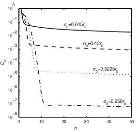
Exact functional form of the capillary eigenmodes depends on the geometry chosen. Despite the LA SRS in a flat capillary is considered in the paper, we suppose that an estimate of the EM seed level will be more useful for applications if inferred from the axi-symmetric theory of the laser beam propagation in a dielectric tube Marcatili ; Andreev . The theory represents an electric field profile at the entrance aperture of the radius as an infinite sum (Ref. CrosPScr, ), where is the overlap integral of the hybrid capillary eigenmode EH1n with the incident laser profile (Fig. 6). Here, is the th zero of the zero-order Bessel function of the first kind, ; for , and , . Fig. 6 shows that about 98% of laser energy is coupled to the fundamental mode for (the perfect matching condition); however, the overlap integral decays very slowly as grows {the analytic fit, , is almost exact for }. When the ratio drops, the larger number of lower-order eigenmodes is effectively excited (up to 5 for ), but contribution from the higher-order modes into the radiation profile at drops sharply (e.g., analytic fit , , holds for ). Therefore, choosing wider capillary is the way of reducing the effect of laser coupling on the forward strongly coupled SRS.
The numerical example of subsection III.2 shows how the SRS under the angle develops in the capillary with an EM seed amplitude characteristic of the axi-symmetric capillary tube by a factor of two wider than in the case of perfect matching. For the parameters of Fig. 4, with the value assigned to , equalizing the effective radial wave number to the resonant wave number gives the resonant mode order corresponding to under the condition (analytic fit was used; see also Fig. 6). One can expect that several modes with can contribute to the effective amplitude of the seed signal. The difference in the mode numbers causes the angular spread around the given scattering angle; this spread should not exceed the admissible value established above, . For and , one has , so that only one capillary mode with can contribute to the scattering under the given angle. Therefore, the seed amplitude used for the numerical demonstration of Fig. 4(a) is evaluated as .
Appendix B Derivation of the exact reflective solution
Omitted in the LHS of Eq. (3b), the Laplace transform (LT) of Eqs. (3) with respect to (LT variable ) and with respect to (LT variable ) gives the set of ODE for the Laplace images ,
| (18) |
where , , , , . The boundary conditions are and . Equations (18) admit the solution
| (19) | |||||
where . Lateral symmetry gives . The Laplace transform inversion of Eq. (19) with respect to reads
| (20) | |||||
where, in accordance with Ref. McKinstrie3, , the expansion is used, and , . Equation (20) includes Laplace images of the three types: , , and . Their inversions read:
| (21) |
expressed through the regularized generalized hypergeometric function IncGamma of variable ;
| (22) |
where , so that , , ; and
| (23) |
which is expressed through the fundamental solutions Kalmykov
| (24) |
where is the incomplete gamma-function of the order of a complex variable (Ref. IncGamma, ). Combining expressions (22), (23), and (21) in Eq. (20) gives the envelope (8a) of the up-going EMW. The amplitude (8b) of the scattering EPW is derived in the similar fashion.
Appendix C Asymptotic reflective solution
The asymptotic can be found by applying the inversion formula, , to the expression (19). The asymptotic behavior at is determined by the singularities of the integrand at , , and with integer and . Expanding in the vicinity of the specific points shows that all the singularities at and give the contribution . Therefore, , and, for a pulse of finite duration, , no contribution comes to the asymptotic from these specific points as soon as the distance from the entrance plane exceeds [or , for ]. (Actually, the Laplace image singularities at and determine the entrance effect, i.e., the waves produced by the seed at the entrance aperture amplified in the pump field in plasma; these waves will inevitably drop behind the laser pulse and their effect therefore vanishes at .) The contribution from ,
thus determines the long-scale evolution of the instability in plasma, which is dominated by the lateral reflections of scattered EMW. Neither (where ) nor are the singularities of the image , so contributions to the asymptotic originate from the singular points only, which are the solutions of the equation [here, ], or , is integer. The fundamental specific point with the maximum real part is the root of the cubic equation which, for arbitrary , admits quite a cumbersome explicit expression. We address to the physically interesting limit of “low leakage”, i.e., , or , which means that the scattered EMW gains more energy between two reflections than loses due to leakage through the wall at one reflection. In this case the lateral convection is mostly suppressed. Solution obtained via the perturbation approach reads . Contribution to the asymptotic from that point is of the order of , which grows in time with an increment . However, the absolute value of grows with , so an evaluation has to be done of the contribution from the points with large . We again use the perturbation approach with the small parameter , that is, , and find the solutions , . Obviously, for , so that contribution from these points to the asymptotic is negligible compared to that from the points with , which is of the order of . Expanding the image in the vicinity of , we arrive at the expression asymptotically valid for ,
which represents the unstable EMW as a quasi-1D exponentially growing mode.
References
- (1) M. D. Perry and G. Mourou, Science 64, 917 (1994), and references therein.
- (2) N. H. Burnett and G. D. Enright, IEEE J. Quantum Electron. QE-26, 1797 (1990).
- (3) X. F. Li, A. L’Huillier, M. Ferray, L. A. Lompré, and G. Mainfray, Phys. Rev. A 39, 5751 (1989).
- (4) T. Tajima and J. M. Dawson, Phys. Rev. Lett. 43, 267 (1979).
- (5) N. E. Andreev, L. M. Gorbunov, V. I. Kirsanov, A. A. Pogosova, and R. R. Ramazashvili, JETP Lett. 55, 571 (1992); P. Sprangle, E. Esarey, J. Krall, and C. Joyce, Phys. Rev. Lett. 69, 2200 (1992); T. Antonsen, Jr. and P. Mora, ibid. 69, 2204 (1992).
- (6) E. Esarey, P. Sprangle, J. Krall, and A. Ting, IEEE Trans. Plasma Sci. PS-24, 252 (1996).
- (7) E. A. J. Marcatili and R. A. Schmeltzer, Bell Syst. Tech. J. 43, 1783 (1964).
- (8) B. Cros, C. Courtois, G. Matthieussent, A. Di Bernardo, D. Batani, N. Andreev, and S. Kuznetsov, Phys. Rev. E 65, 026405 (2002).
- (9) S. Jackel, R. Burris, J. Grun, A. Ting, C. Manka, K. Evans, and J. Kosakowskii, Opt. Lett. 20, 1086 (1995); M. Borghesi, A. J. Mackinnon, R. Gaillard, O. Willi, and A. A. Offenberger, Phys. Rev. Lett. 80, 5349 (1998); F. Dorchies, J.-R. Marquès, B. Cros et al., ibid. 82, 4655 (1999).
- (10) B. Cros, C. Courtios, G. Malka et al., IEEE Trans. Plasma Sci. PS-28, 1071 (2000); C. Courtois, A. Couairon, B. Cros, J.-R. Marquès, and G. Matthieussent, Phys. Plasmas 8, 3445 (2001); N. E. Andreev, B. Cros, L. M. Gorbunov, G. Matthieussent, P. Mora, and R. R. Ramazashvili, ibid. 9, 3999 (2002).
- (11) B. Cros, C. Courtois, J. Godiot et al., Phys. Scr. T107, 125 (2004).
- (12) N. E. Andreev, Y. Nishida, and N. Yugami, Phys. Rev. E 65, 056407 (2002).
- (13) Y. Kitagawa, Y. Sentoku, S. Akamatsu et al., Phys. Rev. Lett. 92, 205002 (2004).
- (14) C. J. McKinstrie, A. V. Kanaev, and E. J. Turano, Phys. Rev. E 56, 1032 (1997); E. J. Turano and C. J. McKinstrie, Phys. Plasmas 7, 5096 (2000).
- (15) C. Courtois, Ph. D. thesis, Université Paris XI, Orsay, 2001 (in French).
- (16) N. E. Andreev, Sov. Phys. JETP 32, 1141 (1971).
- (17) L. M. Gorbunov, Sov. Phys. JETP 40, 689 (1975); D. W. Forslund, J. M. Kindel, and E. L. Lindman, Phys. Fluids 18, 1002 (1975).
- (18) T. M. Antonsen, Jr. and P. Mora, Phys. Fluids B 5, 1440 (1993).
- (19) C. J. McKinstrie, R. Betti, R. E. Giacone, T. Kolber, and E. J. Turano, Phys. Rev. E 51, 3752 (1995); C. J. McKinstrie and E. J. Turano, Phys. Plasmas 4, 3347 (1997).
- (20) N. E. Andreev and S. Yu. Kalmykov, IEEE Trans. Plasma Sci. PS-28, 1201 (2000).
- (21) S. Yu. Kalmykov, Plasma Phys. Rep. 26, 938 (2000).
- (22) Ph. Mounaix, D. Pesme, W. Rozmus, and M. Casanova, Phys. Fluids B 5, 3304 (1993); C. Rousseaux, G. Malka, J. L. Miquel, F. Amiranoff, S. D. Baton, and Ph. Mounaix, Phys. Rev. Lett. 74, 4655 (1995).
- (23) S. V. Bulanov, F. Pegoraro, and A. M. Pukhov, Phys. Rev. Lett. 74, 710 (1995); C. D. Decker, W. B. Mori, K.-C. Tzeng, and T. Katsouleas, Phys. Plasmas 3, 2047 (1996).
- (24) K.-C. Tzeng and W. B. Mori, Phys. Rev. Lett. 81, 104 (1998).
- (25) S. C. Wilks, W. L. Kruer, E. A. Williams, P. Amendt, and D. C. Eder, Phys. Plasmas 2, 274 (1995); C. I. Moore, A. Ting, K. Krushelnick et al., Phys. Rev. Lett. 79, 3909 (1997); E. Esarey, B. Hafizi, R. Hubbard, and P. Sprangle, ibid. 80, 5552 (1998); M. Fomitskyi, C. Chiu, M. Downer, and F. Grigsby, Phys. Plasmas 12, 023103 (2005).
- (26) A. S. Sakharov and V. I. Kirsanov, Phys. Rev. E 49, 3274 (1994).
- (27) D. F. Gordon, B. Hafizi, P. Sprangle, R. F. Hubbard, J. R. Peñano, and W. B. Mori, Phys. Rev. E 64, 046404 (2001).
- (28) D. L. Bobroff and H. A. Haus, J. Appl. Phys. 38, 390 (1967).
- (29) C. B. Darrow, C. Coverdale, M. D. Perry, W. B. Mori, C. Clayton, K. Marsh, and C. Joshi, Phys. Rev. Lett. 69, 442 (1992); A. Ting, K. Krushelnick, H. R. Burris, A. Fisher, C. Manka, and C. I. Moore, Opt. Lett. 21, 1096 (1996); K. Krushelnick, C. I. Moore, A. Ting, and H. R. Burris, Phys. Rev. E 58, 4030 (1998).
- (30) Ph. Mounaix and D. Pesme, Phys. Plasmas 1, 2579 (1994).
- (31) P. Mora and T. M. Antonsen, Jr., Phys. Plasmas 4, 217 (1997).
- (32) N. E. Andreev (private communication, 2002).
- (33) W. B. Mori, C. D. Decker, D. E. Hinkel, and T. Katsouleas, Phys. Rev. Lett. 72, 1482 (1994); C. J. McKinstrie and E. J. Turano, Phys. Plasmas 3, 4683 (1996).
- (34) N. E. Andreev, V. I. Kirsanov, L. M. Gorbunov, and A. S. Sakharov, IEEE Trans. Plasma Sci. PS-24, 363 (1996); N. E. Andreev, L. M. Gorbunov, V. I. Kirsanov, A. A. Pogosova, and A. S. Sakharov, Plasma Phys. Rep. 22, 379 (1996).
- (35) Eric W. Weisstein, Incomplete Gamma Function, http://functions.wolfram.com/06.06.02.0001.01; Regularized Generalized Hypergeometric Function, http://functions.wolfram.com/07.32.06.0035.01. From MathWorld — A Wolfram Web Resource (Wolfram Research, Inc., 100 Trade Center Drive, Champaign, IL 61820-7237, USA);
- (36) S. Yu. Kalmykov, Ph. D. thesis, Associated Institute for High Temperatures, Russian Academy of Sciences, Moscow, 2001 (in Russian).
- (37) A. I. Akhiezer, I. A. Akhiezer, R. V. Polovin, A. G. Sitenko, and K. N. Stepanov, Plasma Electrodynamics, Nonlinear Theory and Fluctuations, Vol. 2 (Pergamon Press, Oxford - New York - Toronto - Sydney - Paris - Braunschweig, 1975), p. 132.
- (38) A. S. Sakharov, Plasma Phys. Rep. 26, 657 (2000).