Orbital Angular Momentum Exchange in an Optical Parametric Oscillator
Abstract
We present a study of orbital angular momentum transfer from pump to down-converted beams in a type-II Optical Parametric Oscillator. Cavity and anisotropy effects are investigated and demostrated to play a central role in the transverse mode dynamics. While the idler beam can oscillate in a Laguerre-Gauss mode, the crystal birefringence induces an astigmatic effect in the signal beam that prevents the resonance of such mode.
pacs:
42.50.Dv; 42.65.Yj; 42.30.-d; 42.50.LcI Introduction
Early experiments have shown that circularly polarized light carries angular mometum A . In a quantum description of light, this angular momentum is associated with the spin of the photon. More recently a significant attention has been given to the study of the orbital angular momentum of light, associated with phase singularities in the wavefront. In a paraxial description of wave propagation, it is found that Laguerre-Gaussian beams carry orbital angular momentum. Such beams can be experimentally produced either through astigmatic mode conversion with cylindrical lenses cillens ; cillens2 or through holographic techniques holog1 ; holog2 ; moire . While the holographic techniques are simpler, the astigmatic mode converters can operate with high power.
It has been demonstrated that parametric down conversion with free propagating beams conserves the Orbital Angular Momentum (OAM) of the pump beam. In the quantum optical domain this was observed through intensity correlation measurements, where twin-photon coincidences were obtained whenever the conservation condition was fulfilled amair . In the classical counterpart, a stimulating beam was introduced and parametric amplification was shown to be conditioned to OAM conservation stimulated . Similar effects have already been observed in second harmonic generation shg1 ; shg2 .
So far, little attention has been given to OAM conservation in intracavity nonlinear coupling. Many studies have been done with transverse multimode OPOs, showing interesting possibilities in pattern formation and quantum images for cavities with degenerate transverse modes, like planar GattiLugiato ; LugiatoGatti and spherical cavities SphericalOPO ; LugiatoMarzoli . Moreover, experiments have shown pattern formation in confocal ConfocalSqz and concentric Mathias cavities, and oscillation in modes with higher order than the fundamental are common in many different experiments Suret ; SaraDucci .
Apart from some theoretical studies on generation of phase singularities with nonlinear optical effects vortex1 ; vortex2 , only a few experimental results have been published in this subject, and to our knowledge, there is no result showing the necessary conditions for intracavity OAM transfer from the pump to the down-converted beams. In the present work, we study the OAM transfer in a non-degenetrate, type-II Optical Parametric Oscillator (OPO). We show the conditions that must be satisfied for the OAM transfer, allowing one of the down-converted beams to oscillate with the same phase singularity of the pump beam. As we shall see, the astigmatism caused by the crystal birrefringence plays a central role in the selection of the beam oscillating in the Laguerre-Gauss mode.
II Experimental Setup
The experimental setup is shown in Fig.1. The OPO is made by two spherical mirrors M1 and M2, with equal curvatures . Inside the cavity, we have a KTP crystal (by Cristal Laser) 10 mm long, cut for noncritical phase matching in 532 nm to 1064 nm down conversion at room temperature. In this case, the crystallographic axes of the cristal are oriented as follows. The axis of the crystal is vertically oriented while the propagation direction lies on the horizontal plane (). The axis forms an angle with respect to the propagation direction.
The mirrors have high reflectance for the infrared (R = 99.8 % @ 1064 nm), and a small transmition at the pump wavelength (R = 92 % @ 532 nm). Crystal losses in the infrared comes mainly from surface reflection, reduced by anti-reflective coating (R = 0.1 %), since crystal absorption at this wavelength is small (0.05 %). For the pump, we have reflection losses (R = 0.5 %) and crystal absorption, increased by gray-tracking effects graytracking .

The cavity length is controlled by a piezo actuator on the mirror, and the cavity is kept nearly confocal, in order to help the alignment and reduce the consequences of the walk-off.
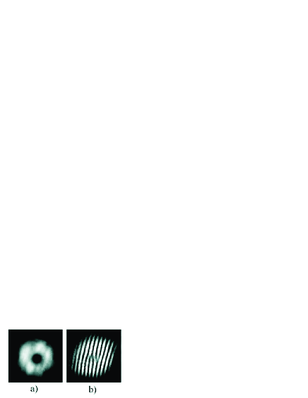
The OPO is pumped by the second harmonic of a Nd:YAG laser (Lightwave 142). This laser generates a TEM00 gaussian beam, that is converted to a nearly Hermite-Gauss TEM01 beam Petrov . With a telescope formed by two cylindrical lenses, we implemented a mode converter that produces a Laguerre-Gauss beam cillens , with a good cylindrical simetry for the intensity and a phase singularity in the center. This phase singularity was evidenced by the self interference pattern obtained in a Michelson interferometer. In Fig.2 we show the transverse profile and interference pattern of the beam used to pump the OPO. The resulting pump power is 60 mW. The beam is horizontally polarized, and mode matched to the cavity with the help of coated lenses.
Although the mirrors were high reflecting at 1064 nm, the output power coming out from the cavity through M2 can be detected by a PIN photodiode. The green light coming from the cavity is filtered by a dichroic mirror (DM), and detected by an amplified Si photodetector (DG). The infrared light is detected by a PIN InGaAs photodiode DIR (ETX-300, from Epitaxx), that samples part of the output beam that is reflected by a beam splitter (BS).
In the output, signal and idler beams are separated by a polarizing cube (PBS). Adopting the usual convention in type-II OPOs, the idler beam polarization is horizontal, and the signal beam has a vertical polarization, alligned to the crystal axis. Each down converted beam is sent into a Michelson interferometer made by a nonpolarizing 50/50 beam splitter (BS) and two flat mirrors, in order to produce interference fringes that can reveal the existence of a phase singularity. The two outputs are recombined in another polarizign cube (PBS) and sent onto a CCD camera, that is used to register either the interference pattern or the intensity profile of the beam.
The output power of the pump and infrared beams is measured as the cavity length is scanned. The corresponding resonance peaks are shown in Fig.3. A wide peak is obtained for the pump, over which narrow dips appear due to the pump depletion in different oscillation regimes. The resonance peaks for the infrared are also shown in Fig.3. They coincide with the depletion dips in the pump resonance. Expanding the curve, we can observe that the depletion dips have a parabolic shape, in good agreement with the depletion expected for a triply resonant OPO Debuisschert . From the finesse of the resonance peak for the pump, we measure 29 % of internal losses in the cavity. For signal and idler modes, the fitting of the parabolic depletion gives a value of 1 % for the infrared losses. The threshold power for parametric oscillation is around 20 mW.

The OPO could be held in the oscillating peaks, and it would rest with a continuous output for as long as 10 minutes. In this situation, we registered the output image of signal and idler beams, as well as their self interference patterns. These images are shown in Fig.4. They are lebeled in correspondence to the oscillation peaks shown in Fig.3.
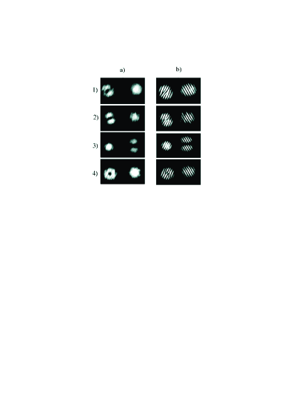
In images 1 and 4, the output intensity in the idler is the one of a Laguerre-Gauss beam. The corresponding interference patterns show the topological defects in the center of the Laguerre-Gauss beam characteristic of phase singularities. In this situation, the idler beam carries the orbital angular momentum of the down converted pump photons. In image 2, the shape of the idler beam is intermediary between a first order Laguerre-Gauss and a diagonal first order Hermite-Gauss modes. A vortex can still be observed through the interference fringes. In both cases, the signal beam remains in the fundamental gaussian mode. Following the Poincaré-sphere representation proposed in Ref.poincare , we can look at the idler mode shown in image 2 as an orbital equivalent of an elliptical polarization.
An interesting effect appears in image 3. In this situation, the signal beam oscillates in the transverse mode with higher order, but with no angular momentum. The output is a pure Hermite-Gauss TEM01 mode, vertically oriented, while the idler remains in the fundamental gaussian mode. Therefore, the orbital angular momentum is not conserved in the parametric down conversion process, and the crystal is expected to suffer a twisting torque. This effect is analogous to the mechanical torque applied to a quater waveplate used for light polarization conversion A , or to a pair of cylindrical lenses used for transverse mode conversion cillens .
The reason for this assimetry in the OAM conservation of the pump can be explained when the propagation of paraxial beams in anisotropic media is investigated and the effect of cavity mode selection is considered.
III Paraxial waves in a birrefringent crystal
In a type-II down conversion, we use the crystal birrefringence to achieve the desired phase matching condition Dmitriev ; Yariv . It was shown by many authors that the paraxial equation, from which we can derive the propagation modes of a beam in free space or isotropic medium, will change when we work with an anisotropic medium Mejias ; Ciattoni . Here we will extend the study of Fleck and Feit FleckFeit of paraxial propagation in uniaxial crystals to the biaxial case, adapting their description to the case of a crystal inside a cavity. Our aim is to reduce the wave equations to the paraxial wave equations that define the Hermite-Gauss modes coupled to the resonances of a linear cavity.
Let us define the crystalographic axis as . The KTP crystal used in our experiment is a quasi-uniaxial one with , where is the refraction index for polarized light. Since the displacement vector satisfies , we can write the wave equation for the electric field , derived from Maxwell’s equations, as
| (1) |
where is the wave number in vacuum corresponding to frequency , and is a constant to be conveniently chosen. This constant will significantly simplify the paraxial propagation analysis in the birrefringent medium. The constitutive relation depends on the dieletric tensor , that is diagonal when we use the crystalographic coordinates
| (2) |
The wave equations for the electric field components can be derived from Eq.(1) by using the constitutive relation and choosing to obtain
Notice that for an uniaxial crystal () we recover the equations obtained in ref.FleckFeit . Let us now consider propagation along an axis lying on the plane with an angle with respect to the crystalographic axis , as shown in Fig.5.

This definition of has the advantage to match the angle and axis definitions usually given by crystal manufacturers. For our KTP crystal, cut for type II phase matching of and nm, we have . A rotated reference frame can be used to describe the propagation inside the crystal. The coordinate transformation between the two frames is
| (4) | |||||
III.1 Plane wave analysis
Two orthogonally polarized plane wave solutions propagating along can be found for Eqs.(III). One with and ( polarized) and another polarized in the plane (). For the polarized solution, only the last of Eqs.(III) remain and its solution is
| (5) |
The plane wave solution polarized on the plane can be found by making in the first two of Eqs.(III). This solution is of the kind
| (6) |
where . From substitution of Eq.(6) in the first one of Eqs.(III), we find
| (7) |
which is the projection of the well known index ellipsoid on the plane. By making and , we get
| (8) |
where is the index of refraction for propagation along . On the other hand, if we substitute Eq.(6) in the constitutive relation and in we find that
| (9) |
Since , this means that and are not orthogonal. Therefore, the Poynting vector , that is orthogonal to , is not parallel to . Let us call the angle between and . A straightforward geometric analysis allows one to obtain a simple relation between and :
| (10) |
This angle is represented in Fig.5. It is related to the well known walk-off effect, which appears as a consequence of the crystal anisotropy. However, as we shall see shortly, the polarized field will also have an anisotropic effect when the propagation of a transversely finite beam is considered. This effect appears as an astigmatic deformation of the beam during the propagation along the crystal.
III.2 Paraxial propagation
On ther other hand, to obtain a direct solution of eq.(1) for a paraxial beam propagation is not so straightforward and some carefull aproximations have to be made to uncouple the diferential equations for each polarization. For the component, the wave equation has the form
| (11) | |||||
To reduce this equation to the paraxial wave equation for polarization, we can begin by eliminating the terms with cross derivatives. One way to do this is to approximate the biaxial crystal by an uniaxial one for the polarization. This is valid since . If we chose , we have for , giving a very small contribution. In the limit these terms will vanish, and we have the uniaxial crystal studied in ref.FleckFeit .
A paraxial solution of Eq.(11) can be obtained if we adopt the rotated reference frame. The resulting equation is close to the paraxial wave equation, except for the assimetry in the coefficients of the transverse second-order derivatives:
| (12) |
The assimetry between the transverse coordinates and appears as a rescaling of the coordinate. This means that the optical beam follows an astigmatic propagation inside the crystal with diferent diffraction scales for each transverse coordinate. Let us separate the dependence of on and making , in order to obtain two paraxial wave equations for the beam diffraction in each transverse direction:
| (13) |
When calculating the propagation of the beam through an OPO cavity, this diffraction assimetry can be seen as a different effective length of the crystal for each transverse dependence of the mode function. For a crystal with length , the effective length for the propagation will be , as usual in the treatment of beam propagation through an uniform crystal Schwob ; Yariv . For , the effective length it will be , resulting in an assimetry in the effective cavity length for each transverse evolution. The calculation of the cavity geometry, and the resulting beam parameters expressed by the Rayleigh length , will therefore differ for the two transverse coordinates.
Let us now turn to the paraxial solution for the field polarized on the plane. Since a plane wave solution with can be found, it is natural to concieve a paraxial solution for which is negligeable. Therefore, if we choose in Eq.(1) and use the rotated coordinates, we obtain the following propagation equation for
| (14) |
We now try a paraxial solution of the form in Eq.(14), using Eq.(8) and making the paraxial approximation to obtain:
| (15) |
where is the walk-off angle given by Eq.(10). In order to obtain a paraxial wave equation, a second coordinate transformation is necessary. This transformation corresponds to a transverse offset of the polarized beam. Using Eq.(8) and defining , we can rewrite Eq.(15) as
| (16) |
that is, the usual paraxial equation with wave vector and a rescaled transverse coordinate . However, since , this transverse rescalling is much smaller than the one present in the polarized field. Therefore, while the polarization has a significant astigmatism but no walk-off, the polarization presents walk-off and a small astigmatism. From now on we shall designate the polarized field as the extraordinary wave and the polarized field as the ordinary wave.
As we made for the component, we can try a factorized solution of the paraxial wave equation (16) of the form , so that
| (17) |
Thus, the paraxial propagation inside the crystal is well described by Eqs.(13) and (17) for the ordinary and extraordinary waves respectively. A paraxial equation for the component of the extraordinary wave can be obtained on the same lines leading to Eq.(17).
IV Astigmatic cavity
All scalling parameters appearing in Eqs.(13) and (17) can be absorbed by a suitable definition of an effective wave number for each transverse direction and for each polarization. This brings Eqs.(13) and (17) to the general form
| (18) |
The normalized solution of Eq.(18) is siegman
| (19) |
where is the Rayleigh length, and is the Hermite polinomial of order . The term is the well known Gouy phase shift. This term avoids multiple resonances of high order Hermite-Gaussian (HG) modes in a high finesse cavity for the signal and idler modes of the OPO. The beam propagation is characterized by the beam waist and the wavefront curvature . The change in the effective wave number is equivalent (in terms of beam diffraction) to the propagation in a shorter length of free space. Since the effective wave number depends both on polarization and transverse direction, we can consider a different propagation length in each case.
Let us now consider the refractive index of the KTP crystal at 1064 nm () and 532 nm (), according to the manufacturer, Cristal Laser S.A. We have, for the extraordinary wave, a refractive index and . From the distance between the mirrors in our near-confocal cavity, and the crystal length , we can calculate the effective length of the cavity for each transverse mode, and for each polarization, in the infrared case. Using the relation
| (20) |
we obtain, from the values of given by Eqs.13,17
| (21) |
where the superscript () refer to the ordinary (extraordinary) wave. The effect of the walk off for the extraordinary wave has been taken into account, but the correction was , and could be neglected. The values of the Rayleigh length inside the cavity () for each transverse direction of the beam, and for each polarization, differ by less than 1%, and cannot be noticed in the free-propagating beam
| (22) |
On the other hand, the total Gouy phase shift accumulated in a round trip inside the cavity will be
| (23) |
The phase added in a round trip depends on the order of the Hermite-Gauss mode resonating inside the cavity. The total Gouy phase for this mode is
| (24) |
From the calculated values of the Gouy phase shift, we see that there will be a small phase diference between the TEM01 and the TEM10 modes. This difference will result in a splitting of the resonance position. At 1064 nm, this separation is of for the ordinary wave, and for the extraordinary one.
In order to study this splitting, we pumped the OPO with a Laguerre-Gaussian (LG) mode obtained with an astigmatic mode converter cillens . The LG mode is the superposition of two HG modes orthogonally oriented, that is, a TEM01 and a TEM10 mode. Once the OPO cavity is scanned, a single resonance peak is expected if the cavity is degenerate for the two TEM modes. Otherwise, two resonance peaks are expected, one corresponding to each TEM mode. In Fig.6, we show the resonance peak of a high finesse cavity for a 532 nm LG pump. The polarization of the pump laser was rotated in order to provide both, the ordinary and extraordinary waves. For the vertical polarization (ordinary wave), a double resonance is observed as expected. This splitting shows a round trip phase difference of , in reasonable good agreement with the predicted for 532 nm. On the other hand, for horizontal polarization (extraordinary wave), the LG resonance presents a single peak. In this case, the splitting is expected to be around , well below the resolution of the cavity used for this measurement.
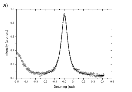
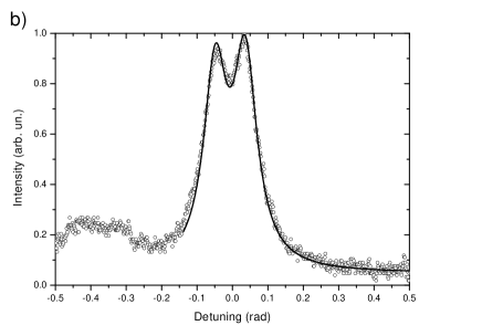
From this analysis we conclude that the OPO can support the oscillation of an LG mode for the extraordinary wave, since its HG components have a degenerate (or quasi-degenerate) resonance frequency. On the other hand, an LG mode in the ordinary wave cannot operate because its HG components will not have the same resonance frequency. This explains the results shown in Fig.4, that is, the orbital angular momentum (OAM) is transferred from the pump laser (extraordinary wave) to the idler mode (extraordinary wave) but not to the signal mode (ordinary wave). Notice that, under our experimental conditions, only one of the down converted modes oscillates in a high order transverse mode, while the other one oscillates in the fundamental transverse mode. So, the OAM exchange between pump, signal and idler modes is governed by the cavity dynamics under the crystal anisotropy, involving polarization and transverse profile aspects.
V Theoretical model
Transverse multimode operation of OPOs has already been theoretically discussed in Ref.Schwob . The pump beam can excite many different cavity modes for signal and idler, but in general it is the one with the lowest threshold that survives. Therefore, modes with best recovering integral should oscillate. To extend this description to our experiment, we must take into account the walk-off and the astigmatism due to the crystal anisotropy. As we have seen, the astigmatism will introduce a phase shift between the two Hermite-Gauss components of the Laguerre-Gauss beam. We can choose to treat the problem either in the Laguerre-Gauss basis or in the Hermite-Gauss one. For the Laguerre-Gauss basis, the astigmatism couples the right-handed beam to the left-handed one. In the Hermite-Gauss basis, this coupling implies in a phase difference between the two first order modes. Here we chose to work in the Hermite-Gauss basis, but the change of basis is straightforward.
In order to study the dynamics of the relevant transverse modes, we shall consider the normalized mode functions , where for pump, signal and idler respectively, and for the Hermite-Gauss TEM00, TEM10 and TEM01 respectively. The overlap integrals,
| (25) |
play an important role in the dynamics since they determine the transverse mode coupling. The mode functions are given by Eqs.(13), (17) and (19), where astigmatism and walk-off effects are taken into account. The walk-off is slightly different for pump (4.1 mrad) and idler (3.2 mrad), and the significant astigmatism occurs in the direction of the signal mode. The integrals are calculated in the whole crystal volume.
With the overlap integrals, we can obtain the dynamic equations for the transverse mode amplitudes. From all possible combinations of oscillating modes, the cavity parity will restrict the number of transverse modes for a given longitudional mode. If there were no anisotropic effects, with a first order Laguerre-Gaussian pump mode, which is odd, signal and idler must have oposite parities in order to give a nonvanishing overlap integral. Therefore, for isotropic propagation, if signal oscillates in a first order mode, idler must oscillate in the fundamental one, and vice-versa. In principle, this parity selection brakes down for an anisotropic medium specially due to walk-off. However, when the overlap integrals are calculated, we can see that the integrals for odd combinations of modes, like or for example, are indeed much smaller than those obtained with an even combination like . This allows us to neglect many of the mode couplings and restrict the number of dynamic equations. Two kinds of operation regimes are observed: either the signal beam oscillates in the fundamental TEM00 mode, while the idler lies in the TEM01 and 10 subspace (peaks 1, 2 and 4 in Fig.3), or the idler beam oscillates in the TEM00 mode (peak 3 in Fig.3). Let us describe these regimes separately.
V.1 Signal beam operating in the TEM00 mode
In this case, the set of dynamic equations for pump, signal and idler transverse mode amplitudes is:
| (26) |
where the subindices , and refer to pump, signal and idler respectively, and , and refer to fundamental (TEM00), vertical (TEM01) and horizontal (TEM10) transverse modes. Pump losses are described by while a common decay rate represents the losses for signal and idler. The respective cavity detunings for pump, signal and idler are , and . The astigmatic symmetry breaking is accounted for through the frequency splitting parameters for pump and for idler. They are calculated with the help of Eq.(24). The pump beam amplitude transmitted through the input mirror is represented by the source term . Since it is prepared in a Laguerre-Gauss mode, the source terms appearing in the dynamic equations for the amplitudes and are out of phase. Finally, is the nonlinear coupling constant.
The dynamic equations, as well as their steady state solutions, are considerably simplified if we express time in units of the cavity round trip time and define the following normalized variables
| (27) | |||||
As before, for pump, signal and idler respectively, and each of the subindices , and may assume the values , or . Cavity losses are around 29% at 532nm and 1% at 1064nm which gives and . In the absence of astigmatism and walk-off the relevant normalized overlap integrals are approximately. When the walk-off effect is considered, the overlap integrals are averaged over the crystal volume. Moreover, the astigmatism is included through the appropriate correction of the mode functions. Taking into account the experimental values for the walk-off and astigmatism parameters we find , and . So, a significant change is obtained only for .
It is instructive to consider the steady state solution of Eqs.(26) in the simplified condition and which correspond to neglecting walk-off and astigmatism. In this case the orbital angular momentum is perfectly transferred to the idler beam which will also oscillate in a Laguerre-Gauss mode with the same topological charge of the pump beam. Therefore, the steady state solutions are
| (28) |
where we defined the normalized intensities . The Laguerre-Gauss amplitudes are given in terms of the Hermite-Gauss amplitudes as
| (29) |
The threshold value of for parametric oscillation is obtained by setting so that
| (30) |
As we shall see, a different threshold condition is obtained for the other operation regime, in which the idler beam operates in the TEM00 mode.
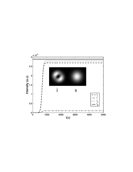
The analytical solution for the steady state including all parameters is cumbersome but Eqs.(28) give us a good estimate for the orders of magnitude. In fact, as we discussed in section IV, the expected value for the pump and idler splitting parameters are ideed very small, and (the splitting parameter is half the astigmatic phase shift calculated from Eq.(24)). However, this small splitting may be responsible for partial transfer of the orbital angular momentum from the pump to the idler mode. In order to illustrate this, we numerically integrated the dynamic equations (26) with a fourth order Runge-Kutta method until the steady state was reached. In Fig.7 this time evolution is shown together with the value given by Eq.(28). In the inset, we show the expected image for signal (S) and idler (I) obtained with the numerical steady state results. A good qualitative agreement is obtained with the experimental results corresponding to peaks 1, 2 and 4 of Fig.3.
V.2 Idler beam operating in the TEM00 mode
In this case the dynamic equations are:
| (31) | |||||
The transverse mode splitting now appears in the dynamic equation for the signal beam and is represented by the parameter . However, the splitting parameter is expected to be of the order of . Since cavity losses in the infrared are of the order of 1%, the corresponding normalized decay rate is , so that . Under such conditions it is impossible for the OPO to support the simultaneous operation of the and modes necessary to compose a Laguerre-Gauss mode. Therefore, the orbital angular momentum cannot be transferred to the down-converted beams. The cavity tuning will select the signal Hermite-Gauss mode whose resonance frequency is closer to the idler resonance. For example, for the cavity frequency falls far away from the signal resonance while the mode gets on resonance. In this case and the steady state solution of Eqs.(31) can be analytically obtained. Notice that the normalized overlap integral will not play any role in this case. We therefore set and use the same normalizations adopted in Eqs.(27) to find
| (32) |
The component of the pump beam does not couple do the down-converted modes so that its steady state solution corresponds just to an empty cavity. On the other hand, the component of the signal beam, as well as the fundamental idler mode, presents a steady state intensity lower than the one found in Eqs.(28) for the same pump level . This corresponds to the situation found in peak 3 of Fig.3, which is clearly lower than the other infrared peaks. Again, the oscillation threshold is readily obtained by taking :
| (33) |
It is twice the threshold value for the case where the orbital angular momentum is transferred for the idler beam, what is also coherent with the lower height of peak 3 in Fig.3.
The numerical evolution of Eqs.(31) using a fourth order Runge-Kutta method was performed without the simplfying assumptions. These results are presented in Fig.8, where the inset shows the expected images for signal and idler. The walk off and astigmatic effects were fully considered and a good agreement with the experimental result was obtained. The theoretical model developed here will be useful for future investigation of the transverse mode dynamics in the quantum domain. Interesting perspectives can be envisaged if the OPO operation is subject to an injected signal. Recent studies on degenerate degen and nondegenerate nondegen parametric processes with injected signal has considered interesting issues like the preparation of quantum correlated states (Einstein-Podolsky-Rosen states) as well as the study of critical behaviours of the OPO operation critical .

VI Conclusion
We have shown that the transfer of orbital angular momentum in intracavity parametric down-conversion is strongly subjected to cavity and anisotropy effects. This can be achieved if pump, signal and idler are in a set of modes where the Hermite-Gauss components of the Laguerre-Gauss mode are degenerate inside the cavity. While that can be easily achieved for the idler beam, the signal beam cannot fullfill this condition unless cavity losses are large. The signal beam can still oscillate in a higher order transverse mode, but in this case, the threshold power increases, and the orbital angular momentum is not transferred to the outcoming beams.
Our results open interesting perspectives related to the quantum regime of the OPO operation. The experimental setup can be used to generate twin beams (intensity difference squeezing) and the production of the optical vortices under squeezed operation can lead to interesting quantum patterns in the down-converted beams. Moreover, the quantum dynamics of the type II operation may lead to entanglement between the polarization and the spatial degrees of freedom juliana . We are theoretically investigating this possibility and an experiment will be setup in the near future.
Acknowledgements.
A.Z.Khoury thanks Prof. D.Petrov for bringing the optical vortices to his attention during the Jorge André Swieca Summer School on Quantum and Nonlinear Optics at Recife-Brazil (2000). The authors thank C.H. Monken and A.G.C. Moura for fruitful discussions. The authors aknowledge partial funding from Coordenação de Aperfeiçoamento de Pessoal de Nível Superior (CAPES/PROCAD and CAPES/COFECUB projects), Fundação de Amparo à Pesquisa do Estado de São Paulo (FAPESP-BR) and Fundação de Amparo à Pesquisa do Estado do Rio de Janeiro (FAPERJ-BR). This work is mainly supported by the Conselho Nacional de Desenvolvimento Científico e Tecnológico (CNPq) through the Instituto do Milênio de Informação Quântica.References
- (1) Corresponding author. E-mail address: khoury@if.uff.br
- (2) R. A. Beth, Phys. Rev. 50, 115 (1936).
- (3) M. W. Beijersbergen, L. Allen, H. E. L. O. var der Veen, and J. P. Woerdman, Opt. Comm. 96, 123-132 (1992).
- (4) E. Abramochkin and V. Volostnikov, Optics Communications 83, 123-135 (1991).
- (5) N.R. Heckenberg, R. McDuff, C.P. Smith, and A.G. White, Optics Letters 17, 221-223 (1992).
- (6) G.F. Brand, American Journal of Physics 67, 55-60 (1999).
- (7) J. A. O. Huguenin, B. Coutinho dos Santos, P. A. M. dos Santos, and A. Z. Khoury, J. Opt. Soc. Am. A 20, 1883-1889 (2003).
- (8) A. Mair, A. Vaziri, G. Weihs, and A. Zeilinger, Nature (London) 412, 313-316 (2001).
- (9) D.P Caetano, M.P. Almeida, P.H. Souto Ribeiro, J.A.O. Huguenin, B. Coutinho dos Santos and A.Z. Khoury, Physical Review A 66, art. no 041801 (Rapid Comm.) (2002).
- (10) K. Dholakia, N.B. Sympson, M.J. Padgett, and L. Allen, Physical Review A 54, R3742-R3745 (1996).
- (11) J. Courtial, K. Dholakia, L. Allen, and M.J. Padgett, Physical Review A 56, 4193-4196 (1997).
- (12) A. Gatti, and L. A. Lugiato, Phys. Rev. A 52, 1675 (1995).
- (13) L. A. Lugiato, and A. Gatti, Phys. Rev. Lett. 70, 3868 (1993).
- (14) M. Marte, H. Ritsch, K. I. Petsas, A. Gatti, L. A. Lugiato, C. Fabre, and D. Leduc, Optics Express 3, 71-80 (1998).
- (15) L. A. Lugiato, and I. Marzoli, Phys. Rev. A 52, 4886 (1995).
- (16) L. A. Lugiato, and Ph. Grangier, J. Opt. Soc. Am. B 14, 225-231 (1997).
- (17) M. Vaupel, A. Maître, and C. Fabre, Phys. Rev. Lett. 83, 5278-5281 (1999).
- (18) S. Ducci, N. Treps, A. Maître, and C. Fabre, Phys. Rev. A 64, art. no 023803 (2001).
- (19) P. Suret, D. Derozier, M. Lefranc,J. Zemmouri, and S. Bielawski J. Opt. Soc. Am. B 19, 395-404 (2002).
- (20) A. V. Mamaev, M. Saffman, and A. A. Zozulya, Phys. Rev. Lett. 77, 4544-4547 (1996).
- (21) Gabriel Molina-Terriza, Lluis Torner, and Dmitri V. Petrov, Opt. Lett. 24, 899-901 (1999).
- (22) B. Boulanger, I. Rousseau, J. P. F ve, M. Maglione, B. M naert, and G. Marnier, IEEE Journal of Quantum Electronics 35, 281-286 (1999).
- (23) Dmitri V. Petrov, Fernando Canal, and Lluis Torner, Opt. Comm. 143, 265-267 (1997).
- (24) T. Debuisschert, A. Sizmann, E. Giacobino, and C. Fabre, J. Opt. Soc. Am. B 10, 1668-1680 (1993).
- (25) M. J. Padgett, and J. Courtial, Opt. Lett. 24, 430-432 (1999).
- (26) V. G. Dmitriev, G. G. Gurzadyan, and D. N. Nikogosyan, Handbook of Nonlinear Optical Crystals, vol. 64 of Springer Series in Optical Sciences. Berlin Heidelberg: Springer-Verlag, first ed., (1991).
- (27) A. Yariv, Quantum Electronics. John Wiley & Sons, third ed. (1988).
- (28) R. Martínez-Herrero, J. M. Movilla, and P. M. Mejías, J. Opt. Soc. Am. A 18, 2009-2014 (2001).
- (29) Alessandro Ciattoni, Gasbriella Cincotti, Damiano Provenziani, and Claudio Palma Phys. Rev. E 66, art. no 036614 (2002).
- (30) J. A. Fleck, and M. D. Feit J. Opt. Soc. Am. 73, 920-926 (1983).
- (31) A. Yariv and P. Yeh, Optical Waves in Crystals. John Wiley & Sons, 1984.
- (32) H. Kogelnik, T. Li; Appl. Opt. 5, 1550 (1966).
- (33) W. A. T. Nogueira, S. P. Walborn, S. Pádua, and C. H. Monken; Phys. Rev. Lett. 86, 4009 (2001).
- (34) C. Schwob, P. F. Cohadon, C. Fabre, M. A. M. Marte, H. Ritsch, A. Gatti, and L. Lugiato; Appl. Phys B 66, 685-699 (1998).
- (35) Technical data from the manufacturer (Cristal Laser S. A.).
- (36) Antony E. Siegman, Lasers, University Science Books (1986).
- (37) M. K. Olsen, K. Dechoum, and L. I. Plimak; Opt. Comm. 223, 123-135 (2003).
- (38) M. K. Olsen, L. I. Plimak, and A. Z. Khoury; Opt. Comm. 215, 101-111 (2003).
- (39) P. Drummond, K. Dechoum, and S. Chaturvedi; Phys. Rev. A 65, art. no 033806 (2002).
- (40) D.P Caetano, P.H. Souto Ribeiro, J.T.C. Pardal, and A.Z. Khoury; Physical Review A 68, art. no 023805 (2003).