Optimizing omnidirectional reflection by multilayer mirrors
Abstract
Periodic layered media can reflect strongly for all incident angles and polarizations in a given frequency range. Quarter-wave stacks at normal incidence are commonplace in the design of such omnidirectional reflectors. We discuss alternative design criteria to optimize these systems.
Keywords: Multilayers, Mirrors, Reflection, Filters
1 Introduction
At optical frequencies, metallic mirrors reflect strongly for any angle of incidence and any polarization. However, they display dissipative losses, which constitutes a drawback in practical applications. Photonic crystals [1] were originally proposed by Yablonovitch [2] to solve this problem: they are periodically microstructured materials that reflect in stop (forbidden) bands within which light propagation is not possible in an infinite structure. Since they are made from transparent materials, photonic crystals can be almost free of losses at any prescribed frequency.
In the one-dimensional case, a photonic crystal is nothing other than a periodic multilayer. Although much attention has been payed to dielectric Bragg mirrors consisting of alternating low- and high-index layers, certain aspects of the reflection by periodic layered media are universal: for periods the reflectance goes to unity as at the band edges, while tends to unity exponentially at the band gaps [3, 4].
This means that, in practice, not very many periods are needed to have a stop band. One is then led to consider stacks of periods (which are often called finite periodic structures) and apply to them conditions that are valid only when the system is strictly infinite. Recently [5, 6], we have put forward this problem and provided an alternative framework for dealing with these finite periodic structures: the trace of the basic period allows us to classify them into three classes with quite different properties.
Concerning the performance of these structures, it is indisputable that Bragg quarter-wave stacks (designed for normal incidence) are the most thoroughly studied in connection with omnidirectional reflection [7, 8, 9, 10, 11, 12]. In spite of this, the current interest in extreme ultraviolet [13] and soft x-ray [14] optics is driving a great deal of work on new methods for optimizing the design of multilayer mirrors. In addition to the simple but cumbersome optimization by eye, only recently more sophisticated techniques have been started to be used [15]: relevant examples include the downhill simplex algorithm [16], the systematic search in the parameters space [17], the simulating annealing [18], the needle variation technique [19], the Levenberg-Marquardt algorithm [20], or genetic algorithms [21]. The aim of this paper is to provide an alternative optimization criterion that has the virtue of using a simple analytical figure of merit with a very clear physical meaning.
2 Notations and general relations
We start by examining the properties of the basic period of our structure, which is assumed to be lossless. The field amplitudes at each side (called ambient and substrate) of the unit cell are related by the complex transfer matrix that can be expressed as [22, 23]
| (1) |
where and are, respectively, the overall reflection and transmission coefficients for a wave incident from the ambient. Note that for identical ambient and substrate media we have , which is equivalent to .
We take as known the theory of reflection from multilayers [4] and its main result for our purposes, namely that strong reflection will occur when (these conditions, one for the polarization and one for the polarization, locate the band stops for each basic polarization).
When we consider a finite periodic system that consists of basic periods, it is possible to show that in the stop bands the reflectance takes the general form [4, 5, 24]
| (2) |
where We are considering only positive values of since negative values can be treated much in the same way.
In practice, it is usual that the basic period of the structure consists of two thin homogeneous dielectric slabs with low, , and high, , indices of refraction and corresponding thicknesses and . These Bragg structures are also appropriately denoted as [LH]N, where is the total number of periods. In such a case, the condition , required to have a stop band, can be written as [12]
| (3) |
where is the phase shift of a wave of wavelength in vacuum in traversing the layer th and is the corresponding optical path, of value
| (4) |
being the angle of incidence. For simplicity, we have assumed that the system is imbedded in air.
The function is
| (5) |
where is the Fresnel reflection coefficient for the interface -. This function is frequency independent but takes different forms for and polarizations. However, one can check that, irrespective of the angle of incidence, the following relation for both basic polarizations holds:
| (6) |
Due to the restriction (6), whenever Eq. (3) is fulfilled for polarization, it is always true also for polarization. In consequence, the -polarization stop bands are more stringent than the corresponding -polarization ones.
Because of historical reasons [25], typical use of dielectric mirrors has been evaluated at normal incidence, with layers at a quarter-wavelength thick (at the design frequency):
| (7) |
The optical paths are equal and maximum reflection occurs at the frequency
| (8) |
which is the center of the stop band.
3 Optimization strategy
In order to explain the optimization criterion we wish to propose, in Fig. 1 we have plotted the reflectance of a Bragg [LH]N structure as a function of the angle of incidence for several values of the number of periods and for polarization. The layer thicknesses are chosen as in Eq. (7).
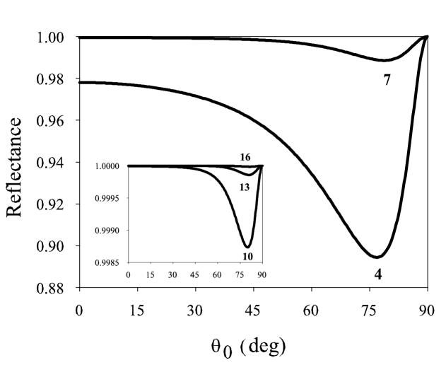
It is clear from this figure the well-known fact that the reflectance tends to unity as increases. It is then hardly surprising that the usual designs found in the literature use the quarter-wave thicknesses at normal incidence without raising any doubt about such assumption. In practice not very many periods (say ) are used in the visible, and one may be tempted to ask whether other thicknesses could improve the performance of the structure. Such a problem could be attacked by a straightforward computation of the reflectance as a function of layer thicknesses. With the a priori information that the optimum condition is close to a quarter wave stack, it will not take too much computational effort to find a reasonable solution [26, 27, 28, 29]. However, our goal here is to provide a more systematic way of dealing with this question.
A reasonable option for optimizing the system is that, when varies from 0 to , the area under the curve (which is the transmittance of the system) would be as small as possible. Therefore, once the materials and the wavelength are fixed, we propose
| (9) |
as figure of merit for the periodic structure. Alternatively, given the characteristic dip appearing in the reflectance for polarization, one could also impose that this dip would be as smaller as possible. We have numerically checked that both criteria give essentially the same results.
For polarization there is no dip. The different behaviour at oblique incidences of and reflectances has been analyzed previously [3]. Since for a given stack the reflectance is greater for polarization than for polarization for every incidence angle (they are equal only at normal and grazing incidences), we argue that once the area is optimized for polarization, it is also improved for polarization, which seems quite plausible.
We have employed an easy-to-use quasi-Newton algorithm in order to find the minimum of the function (9), subject only to the physical conditions and , because the periodic character of the solutions. The numerical results of this optimization are shown in Table 1. Note that the use of adimensional thicknesses and simplifies the presentation of the results, although by no means the results are universal: they apply only to this particular system because we are not considering dispersion in refractive indices (in all the paper we take the wavelength in vacuum m). In any case, the proposed optimization strategy is independent of the particular example under study.
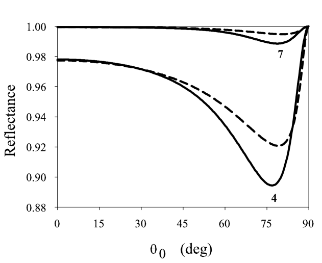
For a better understanding of the performance of our optimized structure, in Fig. 2 we have plotted the reflectance (with and ) and polarization for both the quarter-wave thicknesses as in Eq.(7) and the optimum thicknesses in Table 1. The improvement is remarkable: in terms of areas, we have 20 % and 100 %, respectively.
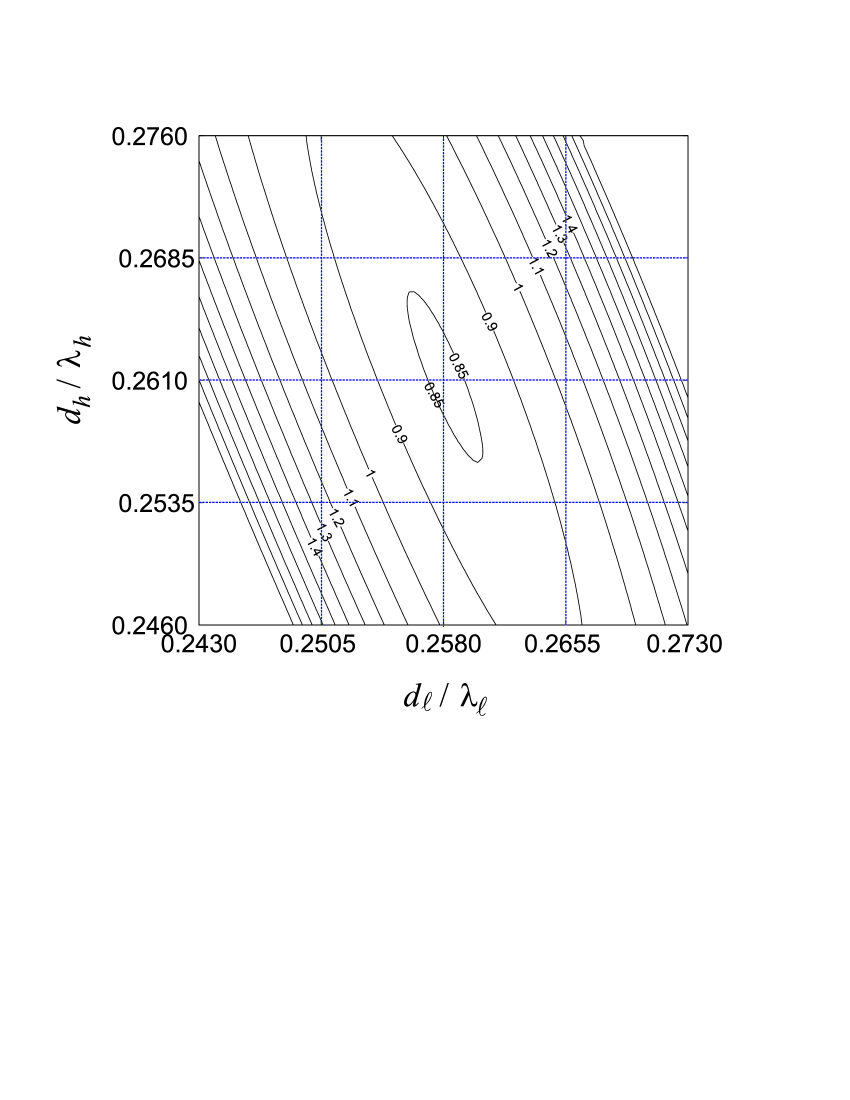
To test the tolerance of the optimum thicknesses against small deviations, in Fig. 3 we have a contour plot of as a function of the adimensional thicknesses and for the same structure as in Fig. 2 with periods. The elliptical contours delimit the range of thicknesses giving a definite value of the area. Moreover, if we take the projection of the major axis of the ellipse on the coordinate axes as a qualitative measure of the maximum tolerance for a given area, we conclude from Fig. 3 that one must be more careful in controlling the thickness than .
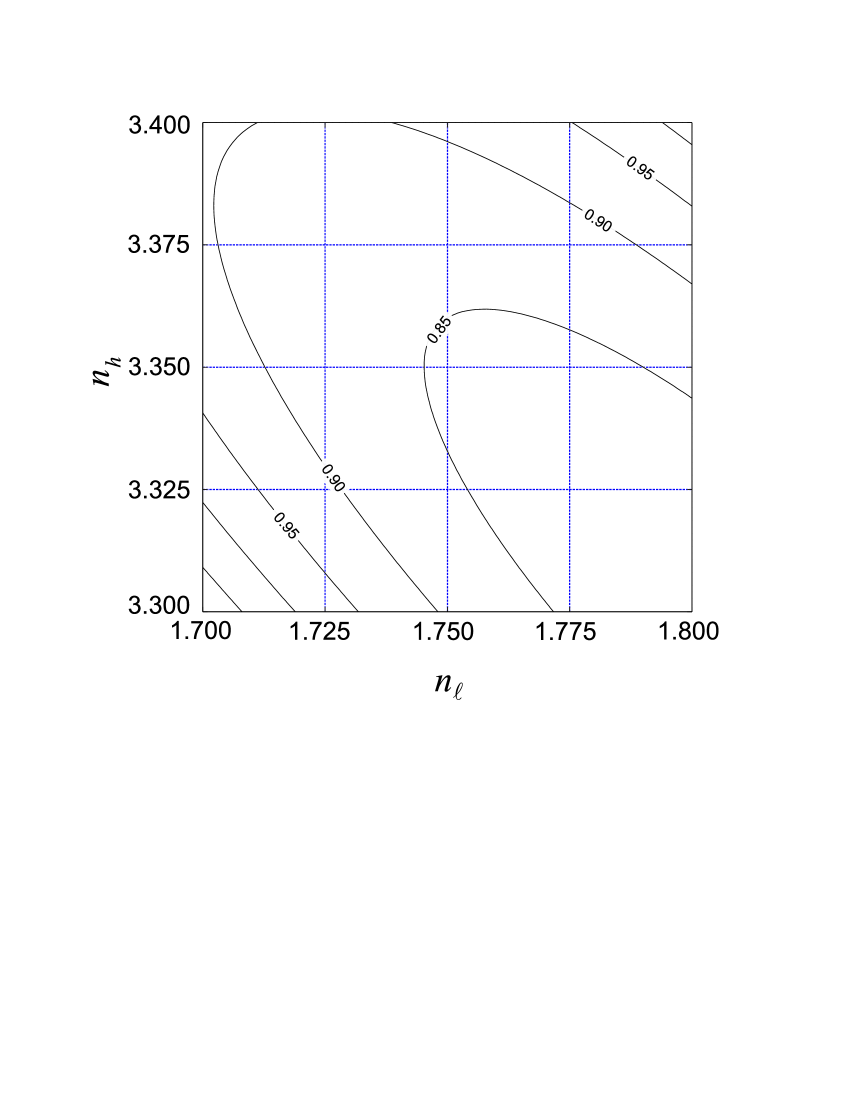
In the same spirit, one could ask about how critical is the behaviour of the area under deviations in the values of refractive indices. In Fig. 4 we have plotted a contour plot of the area as a function of and for the optimum thicknesses and given in Table 1 for . We find again the same kind of elliptical contours as in the previous figure, but now the variation is much smoother, indicating that, roughly speaking, the role of refractive indices is not so crucial as the role of thicknesses.
Obviously, as grows the improvement in the area is larger. In fact, table 1 suggests a considerable improvement that, to some extent, may be illusory: it only concerns a decrease in the integrated transmission, while for the reflection, the improvement is not so impressive. However, the important point is that the improvement is just in the dip of the reflectance. We conclude finally that the method is especially appropriate for moderate values of (), which constitute a typical experimental situation.
The results presented so far hold only for the given ratio of refractive indices. To show that the method can be employed for arbitrary parameters of the multilayers, in Fig. 5 we have plotted the optimum adimensional thickness as a function of the refractive indices for , while in Fig. 6 we have represented the optimum values of . We have assigned a zero thickness whenever the condition , required to have a stop band, is not fulfilled for some values of the incidence angle . The abrupt step is the same in both figures and gives the boundary of omnidirectional reflection for the stack.
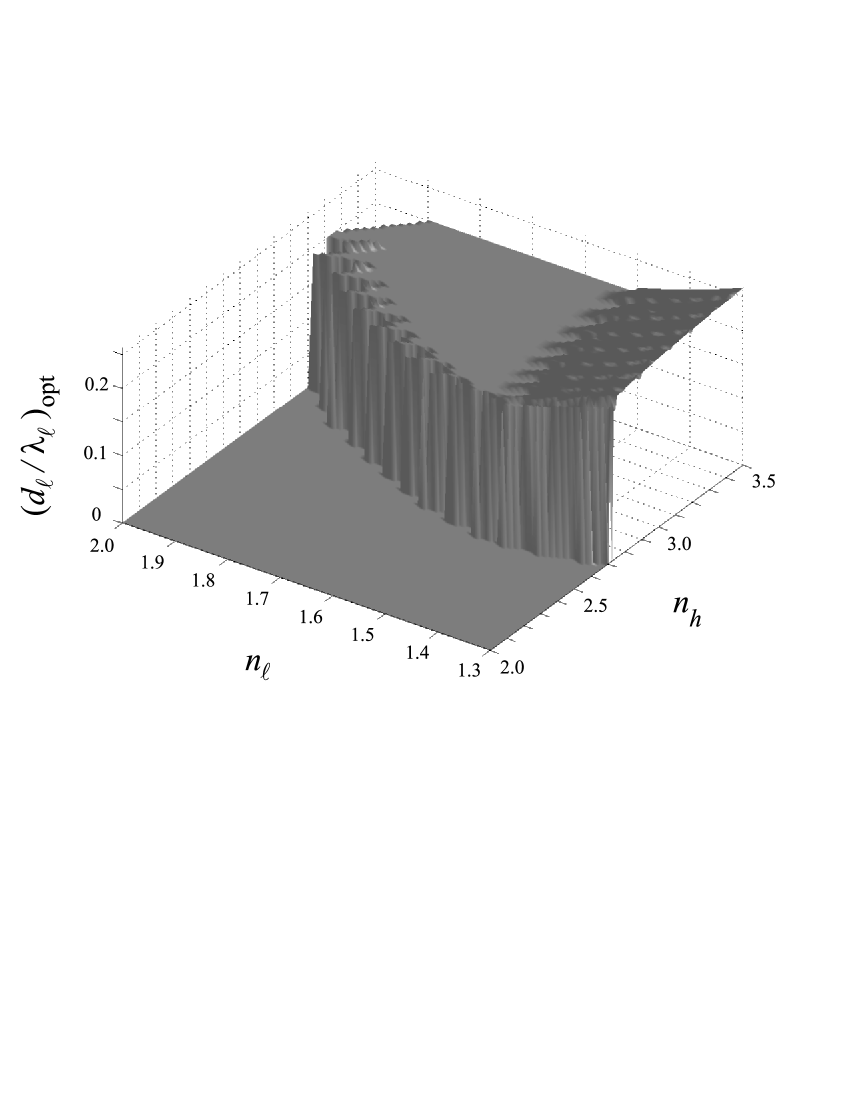
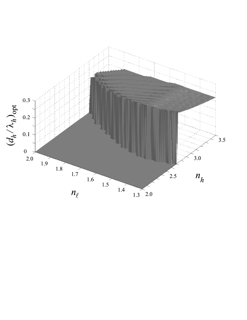
As a general feature, we note that for every pair of allowed refractive indices. In Fig. 5, the optimum thickness varies pronouncedly with until and then it is almost constant, while decreases slowly with in the region of interest. In Fig. 6 we observe that the optimum thickness decreases for a fixed value of (resp. ) when (resp. ) increases, and has a flat variation. The same qualitative behaviour is also observed for other values of .
In summary, we have proposed a simple figure of merit that allows for an improvement in the performance of omnidirectional reflectors, especially when the number of periods is not too large. The method can be easily extended to other materials and wavelengths and predicts optimum thicknesses that can depart from the usual quarter-wave design.
-
Improv. 4 0.2567160 0.2583615 0.6277996 0.7539873 20 % 5 0.2578014 0.2596847 0.2107099 0.2961738 41 % 6 0.2582820 0.2604825 0.7195052 0.1199775 67 % 7 0.2582544 0.2610819 0.2508925 0.5007563 100 % 8 0.2578614 0.2616020 0.8916341 0.2144915 141 % 9 0.2572066 0.2620937 0.3219379 0.9386422 192 % 10 0.2563618 0.2625808 0.1177155 0.4179370 255 % 11 0.2553779 0.2630740 0.4347006 0.1886905 334 % 12 0.2542927 0.2635773 0.1617585 0.8614448 433 % 13 0.2531341 0.2640914 0.6055056 0.3968423 555 % 14 0.2519235 0.2646149 0.2277057 0.1841661 709 %
References
- [1] A complete and up-to-date bibliography on the subject can be found at the web site http://home.earthlink.net/~jpdowling/pbgbib.html.
- [2] Yablonovitch E 1987 Inhibited spontaneous emission in solid-state physics and electronics Phys. Rev. Lett. 58 2059-62
- [3] Lekner J 1987 Theory of Reflection (Dordrecht: Kluwer)
- [4] Yeh P 1988 Optical Waves in Layered Media (New York: Wiley)
- [5] Monzón J J, Yonte T and Sánchez-Soto L L 2003 Characterizing the reflectance of periodic layered media Opt. Commun. 218 43-7
- [6] Barriuso A G, Monzón J J and Sánchez-Soto L L 2003 General unit-disk representation for periodic multilayers Opt. Lett. 28 1501-03
- [7] Fink Y, Winn J N, Fan S, Chen C, Michel J, Joannopoulos J D and Thomas E L 1998 A dielectric mmnidirectional reflector Science 282 1679-82
- [8] Dowling J P 1998 Mirror on the wall: you’re omnidirectional after all? Science 282 1841-2
- [9] Yablonovitch E 1998 Engineered omnidirectional external-reflectivity spectra from one-dimensional layered interference filters Opt. Lett. 23 1648-9
- [10] Chigrin D N, Lavrinenko A V, Yarotsky D A and Gaponenko S V 1999 Observation of total omnidirectional reflection from a one-dimensional dielectric lattice Appl. Phys. A 68 25-8
- [11] Southwell W H 1999 Omnidirectional mirror design with quarter-wave dielectric stacks Appl. Opt. 38 5464-7
- [12] Lekner J 2000 Omnidirectional reflection by multilayer dielectric mirrors J. Opt. A: Pure Appl. Opt. 2 349-53
- [13] Dobisz E A (ed) 2000 Emerging Lithographic Technologies Proc. SPIE 3997
- [14] Freund A K, Ishikawa T, Khounsary A M, Mancini D C, Michette A G, Oestreich S (eds) 2001 Advances in X-Ray Optics Proc. SPIE 4145
- [15] Sánchez del Río M and Pareschi G 2001 Global optimization and reflectivity data fitting for x-ray multilayer mirrors by means of genetic algorithms Proc. SPIE 4145 88-96
- [16] Joensen K D, Voutov P, Szentgyorgyi A, Roll J, Gorenstein P, Hoghoj P and Christensen F E 1995 Design of grazing-incidence multilayer supermirrors for hard-x-ray reflectors Appl. Opt. 34 7935-44
- [17] Mao P H, Harrison F A, Windt D L and Christensen F E, 1995 Optimization of graded multilayer designs for astronomical X-ray telescopes Appl. Opt. 38, 4766-75
- [18] Powell K, Tait J M and Michette A G 2001 Simulated annealing in the design of broadband multilayers containing more than two materials Proc. SPIE 4145, 254-65
- [19] Protopopov V V, Tikhonravov A V, Voronov A V, Trubetskov M K and DeBell G K 1999 Optimal design of graded x-ray multilayer mirrors in the angular and spectral domains Proc. SPIE 3766, 320-6
- [20] Windt D W 1998 IMD-software for modeling the optical properties of multilayer films Comput. in Phys. 12 360-70
- [21] Martin S, Rivory J and Schoenauer M, 1995 Synthesis of optical multilayer systems using genetic algorithms Appl. Opt. 34, 2247-54
- [22] Monzón J J and Sánchez-Soto L L 1999 Lossless multilayers and Lorentz transformations: more than an analogy Opt. Commun. 162 1-6
- [23] Monzón J J and Sánchez-Soto L L 1999 Fully relativisticlike formulation of multilayer optics J. Opt. Soc. Am. A 16, 2013-18
- [24] Cojocaru E 2001 Forbidden gaps in finite periodic and quasi-periodic Cantor-like dielectric multilayers at normal incidence Appl. Opt. 40 6319-26
- [25] Born M and Wolf E 1999 Principles of Optics 7 ed. Sec. 1.6.5. (Cambridge: Cambridge University Press)
- [26] Cox S J and Dobson D C 2000 Band structure optimization of two-dimensional photonic crystals in H-polarization J. Comput. Phys. 158 214-24
- [27] De Dood M J A, Snoeks E, Moroz A and Polman A 2002 Design and optimization of 2D photonic crystal waveguides based on silicon Opt. Quant. Elec. 34, 145-59
- [28] Lee H Y, Makino H, Yao T and Tanaka A, 2002 Si-based omnidirectional reflector and transmission filter optimized at a wavelength of 1.55 m. Appl. Phys. Lett. 81 4502-04
- [29] Vorgul I Y and Marciniak M D, Design and optimisation of multimode 1D photonic band gap waveguide 2002 Opt. Quant. Electron. 34 493-503