Guiding of cold atoms by a red-detuned laser beam of moderate power
Abstract
We report measurements on the guiding of cold 87Rb atoms from a magneto-optical trap by a continuous light beam over a vertical distance of 6.5 mm. For moderate laser power (85 mW) we are able to capture around 40 of the cold atoms. We systematically study the guided fraction as a function of laser power and detuning, and give an analytical expression that agrees well with our results. Although the guide is red-detuned, the optical scattering rate at this detuning (70 GHz) is acceptably low. For lower detuning (30 GHz) a larger fraction was guided but radiation pressure starts to push the atoms upward, effectively lowering the acceleration due to gravity.
pacs:
32.80.Lg, 42.50.Vk, 03.75.-bI Introduction
The development of laser cooling has stimulated a tremendous interest in the confinement and manipulation of cold atoms. In particular the use of dipole forces by far off resonance laser light has become a versatile tool for the manipulation of atomic motion. In this paper we discuss the use of a red-detuned guiding laser as a simple and effective method to transport cold atoms, although we use only moderate laser power. We systematically study the fraction of guided atoms by varying the main parameters laser power and detuning. We also give an analytical expression that gives excellent agreement with the results.
In our experiments so far a cold cloud of 87Rb atoms is collected in a vapor cell magneto-optical trap (MOT) and dropped on an evanescent-wave (EW) mirror CooHil82 ; BalLetOvc87 ; KasWeiChu90 after post-cooling in optical molasses VoiWolCor01 ; VoiWolSpr00 ; WolVoiJan01 . However due to the finite temperature of the cloud, it expands ballistically during the fall, resulting in a decreased density at the surface. This density reduction of atoms falling on the EW could be counteracted in several ways. For example, one could focus the atomic cloud by means of a strong pulse of magnetic field gradient MarGuiBos99 , or combined magnetic and optical pulses Bal97 .
Here we describe our method to guide the atoms by optical light fields, confining them in the transverse direction. The advantage of an optical guide is that it is a well controlled force, that can be applied very locally. The disadvantage of this technique is that atoms potentially scatter photons from the guide, which results in heating and loss of atoms. To overcome this problem of scattering, some groups have used blue-detuned hollow beams SonMilHil99 ; ManOvcGri98 , in which the atoms spend most of their time in the dark inner region of the guide. Such hollow beams cause a low optical scattering rate and can even cool the atoms during reflections at the wall YinZhuWan98 .
The use of a red detuned laser guide has previously been described by several authors. For example, it has been used to transport cold atoms from a production region to a spatially separated trapping region SzyDavAda99 ; DavAda00 . Adiabatic heating and cooling in converging and diverging guiding beams was reported in Ref. PruMarHou99 . A beam splitter for cold atoms has been demonstrated by crossing two red detuned guides HouKadPru00 . These experiments have in common that they make use of high optical power. Red detuned guiding has also been used to capture atoms from a thermal vapor and guide them through hollow fibers RenMonVdo95 .
In this paper we investigate the simplest possible optical guide: a red-detuned Gaussian laser beam of moderate power. The atoms act as high-field seekers and are pulled toward the center of the guiding-beam BjoFreAsh78 . Therefore, the photon scattering rate will be higher than in a hollow guide. However, a Gaussian beam is straightforward to implement, while the scattering rate may still remain at an acceptable level for our purposes. We investigate the performance of the guide for various optical parameters.
II Experimental procedure
The experiment is performed in a glass vapor cell where we create a MOT of 87Rb atoms, 6.5 mm above a BK7 glass prism. Above the prism surface we create an evanescent wave (EW) that is used as an atomic mirror VoiWolCor01 ; VoiWolSpr00 . The purpose of the guiding beam is to confine the atoms while falling towards the EW mirror.
The Rb density in the cell is increased by heating a Rb reservoir. Differential pumping of the cell ensures a constant density long enough to perform an experiment, but it changes on a daily basis. Consequently also the width of the cloud changes on a daily basis. The r.m.s. radius of the cloud, , varies between m and m. The temperature of the cloud is unaffected by the varying density and is K after postcooling in optical molasses.
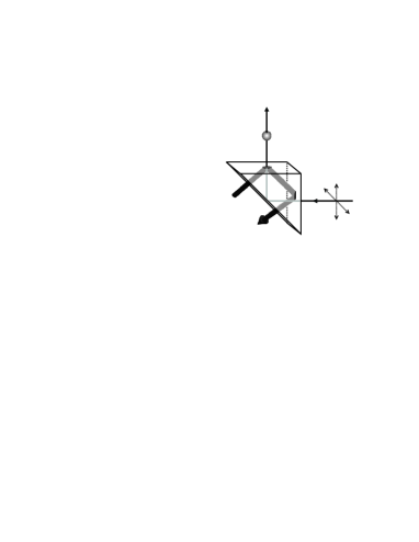
The laser light for the guiding beam is obtained from a home-built tapered amplifier system VoiSchSpr00 . The beam is spatially filtered by sending it through a single-mode optical fiber and linearly polarized by a polarizing beam splitter. The guiding laser was reflected at the hypotenuse of the prism, such that it was pointed upward (see Fig.1). For an optimal result the guiding beam must overlap with the EW as well as with the MOT. To align the beam we mounted some of the steering mirrors on translation stages. This allowed us to translate the beam perpendicular to its propagation direction, and to independently adjust its angle.
We measured the beam profile at various positions along the beam line. The waist ( radius) was found to be m, located at the position of the MOT. The divergence half-angle was mrad. We consider the beam waist to be constant in the mm region between the MOT and the EW. The available power was limited by the tapered-amplifier system and its transmission through the fiber, which reached a maximum of %. We obtained a total power of approximately mW, just before entering the vacuum cell. Because the vacuum cell and the prism are not anti-reflection coated, the available power for guiding is of the power before the cell. Throughout this paper we quote the power of the guiding beam inside the cell, at the position of the MOT. We were able to switch off the beam in s by means of a mechanical shutter, placed before the fiber. The guide was red detuned with respect to the -line, which was measured by a wavemeter (Burleigh, WA-1500).
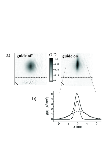
The guiding beam was continuously on during the loading of the MOT, cooling in molasses, and during the fall of the atoms toward the prism. For sufficiently large detuning of the guide, we observed no effect on the MOT or molasses. After cooling in optical molasses, the atoms fall down and a fraction of the atoms is captured in the guiding beam. The atomic distribution is imaged on a CCD camera by resonant absorption imaging at time . Just before we probe the atoms, the guide is switched off, in order not to blind the camera by stray light from the prism. In Fig. 2a we show two absorption images of the atomic cloud, both after falling for ms (just before reaching the prism), with and without the guiding beam present. It is clear that when the guiding beam is on, the density is increased in the cigar-shaped area of the cloud.
III Measurements of guided fraction
In order to determine the guided fraction, we averaged the atomic density distribution in the vertical direction over pixel rows, indicated in Fig. 2a by the thin box. The data are well fitted by a sum of two Gaussians, corresponding to a guided and an unguided fraction PruMarHou99 . The broad distribution represents the unguided atoms and has a r.m.s radius of m, which is the same as the radius of the atomic cloud without the guiding beam present. The narrow distribution in Fig. 2b is the density distribution of the guided atoms. It has a r.m.s. radius of m, slightly smaller than the waist of the guide. From the area of the fitted distributions we extracted the guided fraction.
We measured the fraction of atoms that were guided for ms as a function of potential depth . The depth can be changed by varying either the power or the detuning of the guide. To calculate the potential depth we take the light to be linearly polarized, and far off resonance with respect to the line. The potential is then approximately that of a two-level atom, multiplied by 2/3. This factor is the sum of the squares of the Clebsch-Gordan coefficients, summed over the excited-state hyperfine levels 5, . Note that both hyperfine ground states experience approximately the same potential. A Gaussian beam, with waist , power , and detuning produces a potential depth at the center of the beam of
| (1) |
where MHz is the natural linewidth of the line and mW/cm2 is the saturation intensity. Red detuning corresponds to .
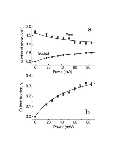
First we measured the guided fraction as a function of guiding power, keeping the detuning fixed at , (Fig. 3). Varying the power from to mW changes the potential depth at the center of the beam from to K. Increasing the power of the guiding beam obviously results in a higher capture fraction of the guide, since the potential becomes deeper. The largest guiding fraction we measured at this detuning was 33 %, at a power of mW. The error bars in the graph are due to uncertainties in determining the number of atoms.
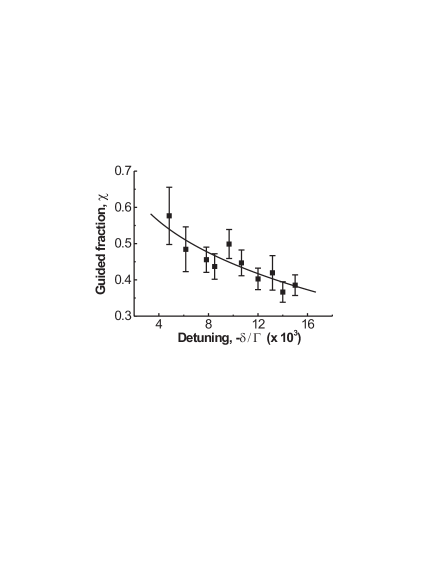
We also varied the potential depth by changing the detuning, keeping the power constant at mW. The guided fraction decreased only slightly when the detuning was varied from (K) to (K), see Fig. 4. As expected the fraction of guided atoms decreased for larger negative values of the detuning, since this leads to decreasing . The range over which we could vary the detuning was limited by the angle of the grating in the master laser of the tapered amplifier. The error bars in Fig. 4 are much larger then the error bars in Fig. 3. This is because the demands on the stability of the system are stronger for this set of measurements because it takes longer to change the detuning than the power.
IV Analysis and discussion
To analyze the experimental data we first remark that the optical potential describing the guide is cylindrically symmetric, and has no influence on the atoms along the direction. The optical potential describing the guide is written as
| (2) |
where is the transverse position in cylindrical coordinates, is the laser waist and the maximum potential depth (at the center of the guiding beam) which is negative due to the sign of the detuning. We assume that the atomic cloud is described by Gaussian distributions for the horizontal position and momentum coordinates.
| (3) |
where is the horizontal momentum, is the temperature of the molasses, and the atomic mass. This distribution is normalized as
| (4) |
Atoms will be bound to the guide if the total of their kinetic and potential energy is negative:
| (5) |
We denote the fraction of molasses atoms which are captured in the guide as . Combining equations 3 and 5 , the guided fraction is written as
| (6) |
which can be evaluated analytically:
| (7) |
Here is the generalized incomplete Gamma function math . Note that the above analysis is similar to that given in Ref. PruMarHou99 . The analytical expression for the guiding fraction was not given in that paper.
From this expression we see that the guided fraction is determined by only two dimensionless parameters: the relative size of the guide compared to the molasses size, , and the depth of the guide compared to the temperature of the molasses, . The factor results from the different definition of the waist of the guide (Eq.2), and the width of the molasses (Eq.3). As expected the guided fraction tends to when either the potential depth or the width of the guiding beam goes to . The fraction increases monotonically when either or increases.
The guiding fraction according to Eq. (7) is plotted in Fig. 3 and Fig. 4 as the solid curve. In the evaluation of Eq. (7) the waist of the Gaussian potential was set to the fixed value of m. The maximum potential depth at the center, , was calculated using Eq. (1). The temperature of the molasses was set to K. The r.m.s. width of the molasses was used as a fit parameter since it was not independently measured and it shows large daily variations as mentioned in section II. Both experimental curves were well fitted by the theoretical function Eq. (7).
In the experiment where the potential depth is varied by varying the power of the guiding beam, the fit resulted in a radius of the molasses of m. The error bar represents the 95% confidence interval. The experiment where the potential depth is varied by changing the detuning resulted in a fit of the radius of the molasses of m.
Not surprisingly the guiding fraction depends strongly on the size of the molasses. When we compare Fig. 3 and Fig. 4 we observe that for the same guide parameters, P=85 mW and , the increase of molasses size reduces the guided fraction from to . Around the experimental parameters the guiding fraction theoretically depends on the size of the molasses as mm-1.
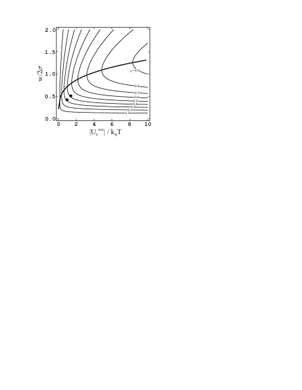
Knowing how to characterize the guiding fraction, we can calculate the optimal width of the guiding beam, given the available power and a chosen detuning for which the scattering rate is at an acceptable level. When the waist of the guide is small, the potential depth is large, but the spatial overlap is not optimal. On the other hand, when the waist is very large, the spatial overlap with the molasses is good, but fast atoms will escape from the low potential. In Fig. 5 the thick line represents the optimum guide waist as a function of the other experimental parameters, which are summarized in a “molasses-matched” potential depth , obtained by setting in equation (1), . Note that this parameter is proportional to the available power and does not depend on the guide waist. The thin lines are lines of constant guiding fraction .
Keeping the power at the maximum 85 mW and choosing the detuning at , the optimum guide waists are determined to be m for the experiment shown in Fig. 3 (m) and m for the experiment shown in Fig. 4 (m). This leads to optimum guiding fractions of 39% and 48% respectively. Our obtained results of and using a beam of m, imply that improvement is possible.
Our purpose of guiding the atomic cloud is to enhance the density of atoms arriving at the surface of the prism, where the EW is located. For mW at , the observed maximum density of atoms inside the guide is cm-3. Comparing this to the value of a free, ballistically spreading cloud, we see a density enhancement of . The guiding fraction can be increased to almost % by raising the depth of the guide to 55 K. However such a large potential depth is obtained by tuning the guide laser closer to resonance, at a detuning of , where radiation pressure by the guide starts to dominate the effect on the atoms, as will be shown in the next section.
V Effect of photon scattering
Up to now the photon scattering due to the guiding beam has not been taken into account. In our experiments we make the potential deeper by decreasing the detuning. Whereas the potential is linear in the detuning (), the scattering rate varies quadratically (). For a typical power of mW, and a detuning of , the photon scattering rate at the center of the guide reaches a value of s-1. During ms of falling, photons are scattered on average. This corresponds to heating of the atoms of K. This is small compared to the initial temperature and we expect no influence on the guiding properties. Indeed, we observed no increase of the width of the unguided fraction when the power was increased.
The direct result of the high scattering rate at low detuning is illustrated in the absorption images in Fig. 6a. All three images are taken at ms after the molasses phase with the guiding beam present, but with different detuning. For decreasing detuning (closer to resonance), the scattering rate increases and radiation-pressure pushes the atoms upward, along the direction of the guiding beam. This results in an apparent gravity less than m/s2. For a detuning , the radiation pressure is such that the guided atoms have fallen mm instead of mm for free falling atoms, due to the acceleration of only m/s2.
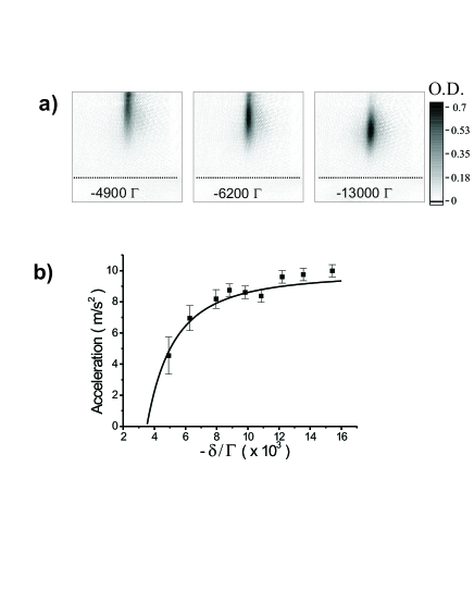
We measured the atomic density profiles between ms and ms for different values of the detuning ranging from to , keeping the power at mW. For each series we determined the vertical acceleration of the guided fraction which is plotted in Fig. 6b. The error bars of the experimental data are mainly due to the fact that the exact initial position of the molasses is uncertain. This location is fitted to be mm outside the field of view of the image. At low detuning, the large errors are the consequence of the fact that a large fraction of the guided cloud is outside the field of view.
The solid curve in Fig. 6b represents the calculated value of the acceleration of the atoms in the guiding potential. To obtain this curve, we calculated the exact dipole-potential and the maximum scattering rate at the center of the trap, . The average scattering rate, is less than this maximum value because the atoms oscillate in the potential. We calculated the classical trajectories for 1000 atoms moving in the dipole potential and time-averaged the intensity experienced by the atoms. In our case the guide has a Gaussian shape, and under the experimental conditions (T=4 K) we obtain an average scattering rate . This ratio is constant to within 5% for the potential range of our experiments. The measured apparent acceleration corresponds well with the theoretical value.
For values above , we observed hardly any influence of radiation pressure by the guiding beam. For such a large detuning, the atoms scatter fewer than 5 photons during their fall, and the guiding fraction is around %. This low scattering rate implies that the atoms could be guided over larger vertical distances. For lower detuning the atoms are pushed upward, resulting in a delayed arrival time at the prism surface due to radiation pressure. The increasing number of scattered photons results in heating of the atomic cloud, visible as the elongation of the atomic cloud in the vertical direction. For the lowest detuning, the width of the cloud is almost 30% larger compared to free falling atoms. During the time the atoms were guided they have scattered on average 25 photons, resulting in a temperature increase of 3 K.
VI Conclusions
We showed the guiding of atoms from optical molasses by a continuous light beam for 28 ms. For a total power of mW and detuning , we guide of the atoms. Although the guide is red-detuned, the optical scattering rate at this detuning is acceptably low. For lower detuning a larger fraction was guided but radiation pressure starts to push the atoms upward, resulting in an acceleration less than gravity. The results of the measured guided fraction corresponded well with an analytical model. The guiding fraction depends only on two dimensionless parameters: the ratio of the widths of the guide and the molasses, and the ratio of the guide depth and molasses temperature. Given the experimental parameters, an optimum value of the guide waist can be determined. For a detuning of , the density enhancement after 28 ms is 2.8, compared with ballistically spreading atoms. This technique is easy to implement and can in principle be used to guide atoms over larger vertical distances. The use of a relatively small detuned laser beam of moderate power makes it easy to implement a guiding beam into every experiment.
Acknowledgments
This work is part of the research program of the “Stichting voor Fundamenteel Onderzoek van de Materie” (FOM) which is financially supported by the “Nederlandse Organisatie voor Wetenschappelijk Onderzoek” (NWO). R.S. has been financially supported by the Royal Netherlands Academy of Arts and Sciences.
References
- (1) R.J. Cook and R.K. Hill, Opt. Commun. 43, 258 (1982).
- (2) V.I. Balykin, V.S. Letokhov, Yu.B. Ovchinnikov, and A.I. Sidorov, Pis ma Zh. Eksp. Teor. Fiz. 45, 282 (1987) [JETP Lett. 45, 353 (1987)].
- (3) M.A. Kasevich, D.S. Weiss, and S. Chu, Opt. Lett. 15, 607 (1990).
- (4) D. Voigt, B.T. Wolschrijn, R.A. Cornelussen, R. Jansen, N. Bhattacharya, H.B. van Linden van den Heuvell, and R.J.C. Spreeuw, C. R. Acad. Sci. Paris, Série IV, t. 2, 619 (2001).
- (5) D. Voigt, B.T. Wolschrijn, R. Jansen, N. Bhattacharya, R.J.C. Spreeuw, and H.B. van Linden van den Heuvell, Phys. Rev. A 61, 063412 (2000).
- (6) B.T. Wolschrijn, D. Voigt, R. Jansen, R.A. Cornelussen, N. Bhattacharya, R.J.C. Spreeuw, and H.B. van Linden van den Heuvell, Phys. Rev. A 64, 065403 (2001).
- (7) E. Maréchal, S. Guibal, J.-L. Bossenec, R. Barbé, J.-C. Keller, and O. Gorceix, Phys. Rev. A 59, 4636 (1999).
- (8) V. I. Balykin, JETP Lett. 66, 349 (1997).
- (9) Y. Song, D. Milam, and W.T. Hill, Opt. Lett. 24, 1805 (1999).
- (10) I. Manek, Yu.B. Ovchinnikov, and R. Grimm, Opt. Commun. 146, 67 (1998).
- (11) J. Yin, Yifu Zhu, and Y. Wang, Phys. Rev. A. 58, 509 (1998).
- (12) K. Szymaniec, H.J. Davies, and C.S. Adams, Europhys. Lett. 45, 450 (1999).
- (13) H.J. Davies and C.S. Adams, J. Phys. B: At. Mol. Opt. Phys. 33, 4079 (2000).
- (14) L. Pruvost, D. Marescaux, O. Houde, and H.T. Duong, Opt. Commun. 166, 199 (1999).
- (15) O. Houde, D. Kadio, and L. Pruvost, Phys. Rev. Lett. 85, 5543 (2000).
- (16) M.J. Renn et al., Phys. Rev. Lett. 75, 3253 (1995).
- (17) J. E. Bjorkholm, R. R. Freeman, A. Ashkin, and D. B. Pearson, Phys. Rev. Lett. 41 1361 (1978).
- (18) D. Voigt, E.C. Schilder, R.J.C. Spreeuw, and H.B. van Linden van den Heuvell, Appl. Phys. B. 72, 279 (2001).
- (19) S. Wolfram, The Mathematica Book, Fourth Edition (Wolfram Media/Cambridge University Press, 1999).