A FAST SWITCHYARD FOR THE TESLA FEL-BEAM
USING A SUPERCONDUCTING TRANSVERSE MODE CAVITY
Abstract
In the present design of the TESLA Linear Collider with integrated X-ray Laser Facility it is necessary that 1 ms long bunch trains with about 10000 bunches are generated and distributed to several free electron laser (FEL) beam lines. The different scientific applications of the X-ray FELs need specific filling patterns of the bunches in the bunch train. It is shown that a fast switch-yard based on a superconducting transverse mode cavity can be used to generate the required bunch pattern in a flexible way while keeping the beam loading in the main linear accelerator constant. The conceptual design of the beam optics and the transverse mode cavity are presented.
1 Introduction
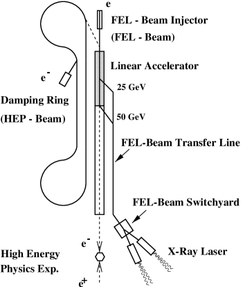
The conceptual design of the TESLA linear collider with integrated x-ray laser facility [1] requires that 1 ms long bunch trains with 11315 bunches are generated and distributed to several free electron laser (FEL) beam lines, while bunch trains with 2882 bunches are accelerated to 250 GeV for high energy physics (HEP) experiments. The e- linear accelerator, the two extraction points (at 25 GeV and 50 GeV) for the FEL-beam and the beam transfer lines are shown schematically in Fig. 1. The first part of the e- linear accelerator is operated at a duty cycle of 10 Hz providing alternately HEP and FEL pulses.
The pulse structure is illustrated in Fig. 2. The mean pulse current is about 10 mA for the HEP and FEL pulses, which guarantees the same beam loading in the cavities for both pulse-types.

Different scientific applications of the X-ray FELs need specific filling patterns of the bunches in the FEL bunch trains [2]. Four examples of filling patterns are shown in Fig. 3(a,b,c,d). Case a is the (standard) 93 ns constant-spacing pattern, while b and c are two examples how the number of bunches and the bunch distance may be varied. Case d is a special case with a much shorter bunch to bunch distance of 769 fs or one GHz rf-bucket.

In the following sections it is shown how filling patterns like Fig. 3(b,c) can be generated from a standard constant-spacing pattern using a fast switchyard based on a transverse mode cavity. A much shorter bunch spacing as in Fig. 3 (d) of course requires a special bunch generation already at the FEL beam injector. Whether such a bunch train can be accelerated up-to 50 GeV without severe cumulative multi-bunch beam break-up is beyond the scope of this paper.
2 Basic Design of a Fast Switchyard
The goal of a fast switchyard is to distribute single bunches or sub-trains of bunches within one 1 ms long bunch train to different beam lines. The typical bunch distance is 120 rf-buckets of the GHz main linac rf-system or . But some scientific application of the FEL require special filling patterns with even shorter and varying bunch distances (see Fig. 3). This requirement can be accomplished by a pulsed superconducting transverse mode cavity operated at a frequency of with a 1 ms rf-pulse duration and a delay line for the laser system of the rf-gun. The GHz deflecting cavity is operated in a pulsed mode similar to the GHz accelerating cavity of the main linac. This avoids rise time or stability problems of the kick applied to individual bunches. The choice of the frequency labels the GHz buckets as even and odd buckets. Bunches in even buckets are kicked into the opposite direction than those in odd buckets, which enables the splitting of one 1 ms long pulse into several sub-bunch trains. The principle is illustrated in Fig. 4: A bunch train is generated with a bunch-to-bunch distance of ns or 120 free GHz buckets with a few exceptions where the distance is ns or 121 buckets.

An even number of buckets between bunches guarantees that all bunches are kicked into the same direction by the transverse mode cavity. An odd number of free buckets between sub-bunch trains results in a switch of the direction of the kick as show in Fig. 4. The additional delay of one rf-bucket (or any odd number of rf-buckets) can be achieved by an optical delay line of the laser beam pulse at the rf-gun.
The beam optics of the switchyard is based on a FODO cell which is shown in Fig. 5. The kick due to the transverse mode cavity is enhanced by a defocusing quadrupole [3]. A bunch offset of at the end of the cavity section, within the quadrupole and at the septum can be achieved with the design parameters summarized in table 1 for two beam energies. In both cases a transverse gradient of 5 MV/m is necessary to provide a kick of () mrad. The details of the cavity design are discussed in the next section.
A cascaded switchyard scheme with a GHz and additional GHz transverse mode cavities would allow the distribution of the bunches of a 1 ms long pulse to four FEL beam lines. The details are not discussed in this paper.

beam energy 25 GeV 50 GeV total kick mrad mrad active cavity length m m transverse gradient MV/m MV/m total length (see Fig. 5) m m quadrupole strength min. beta function m m max. beta function m m
3 Design of the Transverse Mode Cavity
The basic design parameters of a transverse mode cavity are the transverse gradient , the peak magnetic field on the surface , and . The gradient is simply the average of the transverse component of the Lorentz force acting on the beam; for a dipole mode does not depend on the radial position of the beam in the cavity. Superconductivity breaks down when the rf magnetic field exceeds the critical field of T for Niobium. Therefore the transverse gradient is limited by the peak magnetic surface field. A superconducting transverse mode S-band cavity has been operated for an RF particle separator with a transverse gradient of to MV/m [4]. Present design studies of transverse mode cavities at Fermilab [5] are aiming at gradients of MV/m. An accelerating gradient of 25 MV/m in the 1.3 GHz TESLA cavities corresponds to a peak magnetic surface field of T. A similar peak magnetic field of about T corresponds to a transverse gradient of 5 MV/m for the -dipole-mode cavity shown in Fig. 6, which represents one possible shape of a transverse mode cavity with a relatively large iris diameter of 76 mm. The results are obtained with the MAFIA [6] code. A large iris diameter is advantageous with respect to wakefield effects but requires a special matching cell at the end of the cavity to achieve good field flatness of the dipole mode.

Frequency GHz Ohm Ohm Number of active cells Active length m Transverse gradient MV/m Peak magnetic field T Q-value RF heat load (5 Hz, 2 K) W External Q-value Filling time RF-peak-power kW
Further important parameters are and , which are defined according to the equations:
| (1) |
where is the stored energy of the cavity mode and the BCS-resistivity of Niobium. The parameter is essentially the ratio of the square of the transverse gradient to the energy which is stored in the cavity mode. is a purely geometrical parameter which relates the surface resistivity to the Q-value of the cavity. The BCS resistivity for the GHz cavity at 2 K has been scaled from the GHz TESLA accelerating cavity according to
| (2) |
and using a Q-value of for the TESLA cavity. The dissipated power at 2 K during one pulse for one transverse mode cavity with an active length of m is 16 W according to
| (3) |
with , resulting in a average rf heat load of W for a 5 Hz operation. The same formula can be used to calculate the required rf-peak-power by using the external , , which is determined by the coupling. An external of has been chosen, for which one obtains a filling time of () which is similar to the filling time of the GHz TESLA accelerating cavity.
The switchyard for a 25 GeV (50 GeV) beam would require seven (ten) transverse mode cavities with the parameters considered in table 2. The total rf-peak-power for 17 cavities is kW and the total rf heat load is 2 W at 2 K for a 5 Hz operation.
4 Conclusion
It is feasible to distribute single bunches or sub-bunch trains out of a 1 ms long bunch train to two beam lines using a fast switchyard based on a transverse mode cavity operated at GHz. The conceptual design of the beam optics and the dipole mode cavity have been presented. An engineering design of the system would require further studies for the following subsystems: delay line of the laser pulse at the rf-gun, integration of a dispersion suppression and a collimation section into the beam optics, and design of fundamental mode dampers at the transverse mode cavity. Depending on the required bunch pattern it is possible to double the beam time for scientific applications (e.g. pump and probe experiments) with a fast switchyard.
Acknowledgments
I would like to thank J. Rossbach for discussions and contributing ideas for the basic design of a fast switchyard. Thanks go also to H. Edwards and M. McAshan for their kind hospitality during my visit at Fermilab in 1999 where I became involved in the design of transverse mode cavities. Furthermore I would like to thank M. Lomperski for carefully reading the manuscript during breakfast.
References
- [1] R. Brinkmann, G. Materlik, J. Rossbach, A. Wagner eds. Conceptual Design of a 500 GeV e+e- Linear Collider with Integrated X-ray Laser Facility, DESY 1997-048, ECFA 1997-182
- [2] G. Materlik, FEL User Requirements , TESLA TDR Meeting, Zeuthen, Feb. 3-9, 2000
- [3] J. Rossbach, private communications, DESY
- [4] A. Citron, et al. First Operation of a Superconducting RF-Particle Separator NIM 155, 1978, p 93-96
- [5] J. D. Fuerst et al., An RF Separated Kaon Beam from the Main Injector: Superconducting Aspects, FERMILAB-TM-2060
- [6] T. Weiland, On the numerical solution of Maxwell’s Equations and Applications in the Field of Accelerator Physics, Part. Acc. 15 (1984), 245-292