Experimental Evidence of Time Delay Induced Death in Coupled Limit Cycle Oscillators
Abstract
Experimental observations of time delay induced amplitude death in
a pair of coupled nonlinear electronic circuits that are
individually capable of exhibiting limit cycle oscillations are
described. In particular, the existence of multiply connected
death islands in the parameter space of the coupling
strength and the time delay parameter for coupled identical
oscillators is established. The existence of such regions was
predicted earlier on theoretical grounds in [Phys. Rev. Lett.
80, 5109 (1998); Physica 129D, 15 (1999)]. The
experiments also reveal the occurrence of multiple frequency
states, frequency suppression of oscillations with increased time
delay and the onset of both
in-phase and anti-phase collective oscillations.
PACS numbers: 05.45.Xt, 87.10.+e
Coupled limit cycle oscillator models have been extensively studied in recent years because of the useful insights they provide into the collective behaviour of many physical, chemical and biological systems [2, 3, 4, 5]. One of the simplest such models, the so-called Kuramoto model [2], which retains only the phase information of each oscillator and is valid in the limit of weak mutual couplings, displays a spontaneous transition to a synchronized collective state of a single frequency when the coupling strength exceeds a critical value. Similar collective behaviour is observed in many natural systems, such as the synchronous flashing of fireflies, the phase locking of cardiac pacemaker cells, and the collective chirping of crickets [5]. Phase locking has also been demonstrated experimentally in arrays of coupled nonlinear electronic circuits [6]. When the coupling becomes stronger, amplitude effects become important and give rise to other interesting collective states, such as that of amplitude death in which the various oscillators pull each other off their periodic states and collapse to a state of zero amplitude. The condition for such a state to occur is for the oscillators to have a broad dispersion in their natural frequencies and for the coupling strength to exceed a threshold value. Thus, as has been pointed out in a number of theoretical studies [7], a collection of identical limit cycle oscillators cannot display amplitude death. However, more recent investigations [8] indicate that the presence of finite propagation time delays in the coupling removes this restriction and predict the possibility of inducing the death state even in a system of two coupled identical limit cycle oscillators. Time delay is ubiquitous in most physical systems due to finite propagation speeds of signals, finite chemical reaction times, finite response times of synapses, etc., and its influence on the collective dynamics of coupled systems can have wide-ranging implications [9]. It is important therefore to establish the experimental feasibility of such a death phenomenon.
In this Letter we present experimental observations on time delay induced death in two coupled nonlinear circuits that are individually capable of exhibiting limit cycle oscillations. A specially designed digital delay line gives precise control over the delay time in the coupling and permits us to explore a large area of parameter space. Observations on the phenomenon of amplitude death have recently been reported [10] for a pair of optothermal oscillators that are thermally coupled and for which the occurrence of death for strong couplings and its relation to Hopf bifurcations of the uncoupled and coupled systems have been experimentally verified. However, as the authors themselves point out, their experimental results are not conclusive about the role of delay in the death phenomenon and in particular they have not investigated the phenomenon of death islands or, indeed, that of the multiplicity of death islands predicted by the theory of time delay induced death [8]. In our experiments we provide clear evidence of time delay induced death islands and their multiple connectedness in the parameter space defined by the coupling strength, time delay and frequency, for the case of two coupled identical oscillators. We also find the existence of multiple frequency states, frequency suppression of oscillations with increased time delay and the onset of both in-phase and anti-phase collective oscillations.
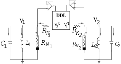
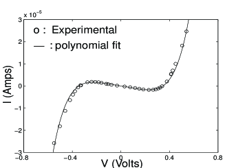
Our experimental system, schematically shown in Fig. 1, consists of two nonlinear circuits coupled through a digital delay line (DDL). The individual oscillator circuits are a variant of the so-called Chua circuit, which has been widely employed in a number of nonlinear dynamical studies [11]. The nonlinear resistive element has the typical characteristic, with negative resistance around the origin and positive slopes away from the origin as shown in Fig. 2. This enables each individual oscillator circuit in the uncoupled state to sustain limit cycle oscillations with a characteristic frequency of . The two channel DDL taps the input signal at a certain rate using an analog to digital converter (in this case an ADC0809 with a conversion rate of s) and stores it in a random access memory (RAM) bank. The stored bits are read using a logical circuit and converted back to an analog signal to be fed back into the circuit. The coupling between the oscillators is linear, resistive and proportional to the difference in the signal strengths of the two oscillators with a time delay. The coupling strength is varied by changing the resistances () that join the two oscillators. By using the current summation rules at nodes and , a theoretical description of the circuit can be given as,
| (1) |
where and Amp/F, the nonlinear damping factor, is obtained from an empirical fit of the characteristics of the nonlinear resistive element as shown in Fig. 2. The frequencies are and the coupling strengths . For our experiments on identical oscillators we have fixed and varied and such that spans the range of to .
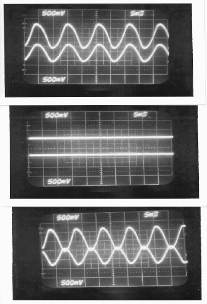
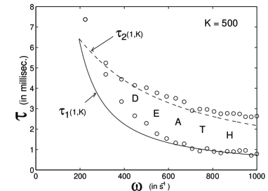
The coupling strength varies in the range of to . Examples of our experimental results for the time evolution of the oscillator voltages as a function of the delay parameter are shown in Fig. 3 for and . The identical oscillators acquire an in-phase locked state (for ms), death (for ms) and an anti-phase locked state (for ms). A series of such observations are recorded for a fixed frequency and at different fixed values of by varying the time delay parameter. The output voltage of the oscillator is monitored on the oscilloscope up to the point where it shows a sudden drop in value by several orders of magnitude, i.e., nearly to zero. The value of is further increased up to the point where the signal from the oscillator again suddenly revives to a large value. An entire parameter space in for amplitude death is thereby explored. In Fig. 4 the solid squares are the experimental data points marking the loci of the death regions. They clearly reveal closed death island regions in the plane of the coupling strength, , and the time delay, , for the common frequency of .

The solid and dashed lines are analytic curves obtained from a linear stability analysis of the origin for the model equation (1). These curves are derived in a standard manner [8] from the characteristic equation for the eigenvalue , namely, , and are given by,
| (2) | |||||
| (3) |
where , and . The region enclosed by the intersection of and is the primary death island and that enclosed between and is the secondary (higher order) death island. We observe that the experimental observations not only display topological similarity to the analytic predictions but are also in good quantitative agreement with them. The deviations observed are primarily due to two reasons. First, the analytic domains are sensitive to the values of the coefficients used in fitting the characteristic of the nonlinear resistive element. The relative downward shift and larger width of the experimental islands compared to the analytic region are due to these estimation errors. Second, the deviation at very high values of (and hence low ) is related to limitations on the maximum current that can flow through for the rated biased voltages of our experimental circuit. The existence of the higher order island is particularly significant since it confirms the theoretical finding of multiple connectivity of the stability region of the origin [8].
In Fig. 5, the experimental death region is shown at a constant coupling strength for different values of the frequency. The death region ceases to exist below a certain threshold frequency, in accordance with theoretical predictions [8]. On either side of this region, there are phase locked states exhibiting in-phase locked oscillations for small time delays and anti-phase locked oscillations for longer time delays.
Another important characteristic of time delay systems in general [12, 13], and delay coupled limit cycle oscillators in particular [8], is the existence of multiple phase locked states. When the oscillators are identical, these phase locked states coincide with in-phase (phase difference, ) and anti-phase () solutions. In Fig. 6(a), the domains of existence of these solutions in space are indicated. Here represent the in-phase solutions and represent the anti-phase solutions. These domains have been determined experimentally. For a fixed the various existing multiple states can be accessed with slight perturbations to the system, i.e., by slightly changing the initial conditions. We have also observed hysteretic behaviour between the various branches. In Fig. 6(b), the frequencies of the first few multiple states are plotted for increasing values of . Note that the collective states can be much higher than the individual oscillator frequencies and that

their magnitude decreases with
increasing values of time delay. Such a phenomenon of time delay
induced frequency suppression has been discussed earlier in the
context of phase only oscillators [12].
In conclusion, we have experimentally demonstrated for the first
time the existence of delay induced amplitude death in a pair of
coupled identical nonlinear oscillators [8]. We have
also demonstrated the coexistence of in-phase and anti-phase
states with multiple frequencies and the suppression of the common
frequency with time delay. The observation of multiply connected
death islands (for identical oscillators) in the parameter space
of the coupling strength and time delay is our most important
result. This result not only bears topological
resemblance to earlier model calculations [8],
but also shows good quantitative agreement with analytic estimates
obtained from a theoretical model of the experimental circuits.
It should be noted that our experimental system of coupled
nonlinear electronic circuits (and its theoretical model) is
capable of richer nonlinear behaviour and goes beyond the simple
normal form model used in previous theoretical studies
[8]. In this sense the results on delay induced
amplitude death can be
said to have a broader validity and therefore wider applicability
to physically realistic systems.
We now briefly discuss a few interesting directions for future experiments that are relevant to our present results as well as to practical applications. A natural next step is to couple more than two oscillators to explore some of the other theoretical predictions discussed in [8]. The principal technical challenge and the major expensive elements for such an endeavor are the construction of additional delay lines with enhanced number of channels. Such an effort is presently underway. Another interesting possibility is to move away from the limit cycle regime and investigate the effect of time delay on the synchronization of coupled chaotic oscillators - an area of much current scientific interest [14]. In principle this should be possible with our present experimental system since the basic Chua circuits are capable of displaying chaotic oscillations. It would be necessary however to employ a faster delay line. Time delay could facilitate phase synchronization in view of its significant influence on phenomena like phase slips [15]. A final area of practical interest is the stability of these limit cycle collective states to external noise. Past numerical studies indicate that time delay induced higher frequency states can exhibit metastable behaviour and decay to the lowest periodic state in the presence of sufficient external noise [12]. We do not observe this behaviour since by design our system has very low intrinsic (thermal) noise in order to facilitate access to the higher frequency states. It would be interesting to introduce a suitably designed noise source in the individual oscillator circuits to experimentally test these theoretical predictions including the influence of noise on the threshold for onset of synchronization [16].
We acknowledge the important contribution of H. S. Mazumdar in the design, development and construction of the digital delay line.
REFERENCES
- [1] Present Address: EduTron Corp., 5 Cox Rd., Winchester, MA 01890.
- [2] Y. Kuramoto and I. Nishikawa, J. Stat. Phys. 49, 569 (1987).
- [3] A. Hohl, A. Gavrielides, T. Erneux, and V. Kovanis, Phys. Rev. Lett. 78, 4745 (1997); J. Benford, H. Sze, W. Woo, R. R. Smith, and B. Harteneck, Phys. Rev. Lett. 62, 969 (1989).
- [4] M. F. Crowley and I. R. Epstein, J. Phys. Chem. 93, 2496 (1989); M. Yoshimoto, K. Yoshikawa, and Y. Mori, Phys. Rev. E 47, 864 (1993).
- [5] J. J. Collins and I. N. Stewart, J. Nonlinear Science 3, 341 (1993); M. A. Branham and M. D. Greenfield, Nature 381, 745 (1996); M. Kawato and R. Suzuki, J. Theor. Biol. 86, 547 (1980); E. Sismondo, Science 249, 55 (1990)
- [6] A. A. Brailove and P.S. Linsay, Int. J. Bifurcation Chaos 6, 1211 (1996).
- [7] D. G. Aronson, G. B. Ermentrout, and N. Kopell, Physica (Amsterdam) 41D, 403 (1990); P. C. Matthews and S. H. Strogatz, Phys. Rev. Lett. 65, (1990); P. C. Matthews, R. E. Mirollo, and S. H. Strogatz, Physica D 52, 293 (1991).
- [8] D. V. Ramana Reddy, A. Sen, and G. L. Johnston, Phys. Rev. Lett. 80, 5109 (1998); D. V. Ramana Reddy, A. Sen, and G. L. Johnston, Physica (Amsterdam) 129D, 15 (1999).
- [9] S. H. Strogatz, Nature (London) 394, 316 (1998).
- [10] R. Herrero, M. Figueras, J. Rius, F. Pi, and G. Orriols, Phys. Rev. Lett. 84, 5312 (2000).
- [11] M. Komuro, R. Tokunaga, T. Matsumoto, L.O. Chua, and A. Hotta, Int. J. Bifurcation and Chaos 1, 139 (1991), and references therein; Chua’s Circuit: A Paradigm for Chaos, edited by R. N. Madan (World Scientific, Singapore, 1993).
- [12] E. Niebur, H. G. Schuster, and D. Kammen, Phys. Rev. Lett. 67, 2753 (1991).
- [13] S. Kim, S. H. Park, and C. S. Ryu, Phys. Rev. Lett. 79, 2911 (1997); M. K. S. Yeung and S. H. Strogatz, Phys. Rev. Lett. 82, 648 (1999).
- [14] M. G. Rosenblum, A. S. Pikovsky, and J. Kurths, Phys. Rev. Lett. 76 (1996) 1804.
- [15] D. V. Ramana Reddy, A. Sen, and G. L. Johnston, Physica (Amsterdam) 144D (2000) 336.
- [16] M. Shiino, Phys. Lett. A 111, 396 (1985).