Triggering BTeV
Abstract
BTeV is a collider experiment at Fermilab designed for precision studies of CP violation and mixing. Unlike most collider experiments, the BTeV detector has a forward geometry that is optimized for the measurement of and charm decays in a high-rate environment. While the rate of production gives BTeV an advantage of almost four orders of magnitude over factories, the BTeV Level 1 trigger must be able to accept data at a rate of 100 Gigabytes per second, reconstruct tracks and vertices, trigger on events with high efficiency, and reject minimum bias events by a factor of 100:1. An overview of the Level 1 trigger will be presented.
I Introduction
The BTeV experiment at Fermilab is expected to begin running in the new Tevatron C0 interaction region by the year 2005. The physics goals include studies of CP violation and mixing, rare decays, and high sensitivity searches for decays forbidden within the Standard Model. The primary focus of BTeV is on precision studies of CP violation and mixing in decays.
BTeV benefits from the new Fermilab Main Injector, which was built to achieve higher luminosity in the Tevatron. With a luminosity of the Tevatron can produce hadrons in seconds of running. This rate of production is almost four orders of magnitude larger than the production rate anticipated for colliders operating at the resonance.
In this paper I describe the Level 1 trigger for BTeV. I begin with an overview of the BTeV detector and the operating environment in the C0 interaction region. I describe the baseline design of the silicon pixel vertex detector, which provides the data for the Level 1 trigger. The Level 1 trigger performs track and vertex reconstruction to select events with detached vertices. The goal is to trigger on decays with high efficiency, while rejecting minimum bias (light quark) events.
Details of the baseline design of the Level 1 trigger have been published [1]. Here I provide an overview of the Level 1 trigger, report on results from trigger simulations, and present some new ideas for track and vertex reconstruction algorithms that challenge our baseline design. Our design for both the trigger and the vertex detector will undoubtedly evolve as we refine our understanding of detector hardware and physics simulations.
II The BTeV Detector
BTeV is optimized for physics. The detector is a two-arm forward-geometry spectrometer (see FIG. 1) designed to run at a luminosity of and a production rate of hadrons per year. This rate of production is high. However, the background from light quark events is also large, with only 1 in 1000 events expected to be a event. To select a broad spectrum of events efficiently, BTeV will reconstruct tracks and vertices with a Level 1 trigger that receives data from a state-of-the-art vertex detector. The Level 1 trigger selects decays by reconstructing primary-interaction vertices, and by identifying tracks that are not associated with a primary vertex. The goal is to trigger on tracks that come from decays, which are found as secondary vertices detached from a primary vertex.
The trigger and vertex detector operate in a high-rate hadron-collider environment. Like all of the new collider experiments in the Tevatron, BTeV is being designed to operate with a Tevatron bunch spacing of 132 ns. Unlike most hadron collider experiments, BTeV operates in a region with high track density, due to the forward geometry. BTeV also operates close to the Tevatron beams (the innermost edge of the vertex detector is within 6 mm of the beams), and design considerations for both the vertex detector and the Level 1 trigger involve studies with beam luminosities in excess of . At the mean number of interactions per beam crossing is expected to be 2. Although events with two or more interaction vertices could pose a problem for a Level 1 trigger designed to trigger on detached vertices, the BTeV trigger benefits from a long interaction region with , and is designed to be relatively insensitive to multiple interactions per beam crossing. Simulations show that the Level 1 trigger selects less than 1 of minimum bias interactions, even up to a luminosity of .
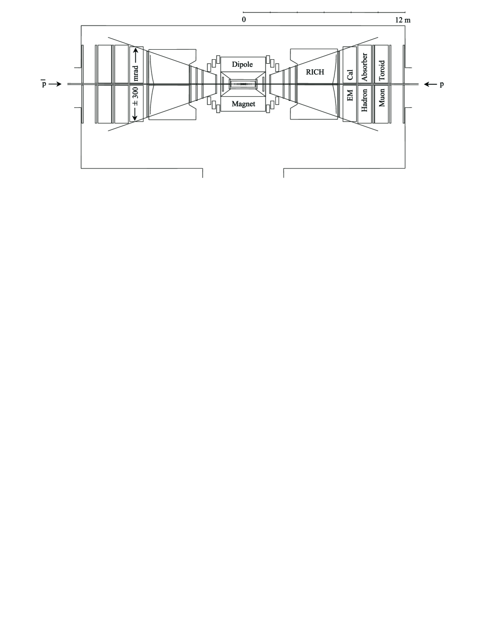
The two-arm forward-geometry design of the BTeV spectrometer is accompanied by significant design challenges. However, the forward geometry provides considerable advantages for physics [2], compared to a more central detector. The main advantage is a larger Lorentz boost, which increases the reconstruction efficiency for decays and improves the proper time resolution. Another significant advantage is that a forward spectrometer can have a much longer detector volume, and we exploit this aspect of the geometry by including state-of-the-art particle identification for hadrons. Furthermore, having a two-arm configuration with a dipole magnet centered on the interaction region means that BTeV has two spectrometers, thereby doubling the acceptance for physics compared to a single-arm spectrometer. As a double-arm spectrometer, BTeV covers both the forward and the backward rapidity regions with a combined coverage of .
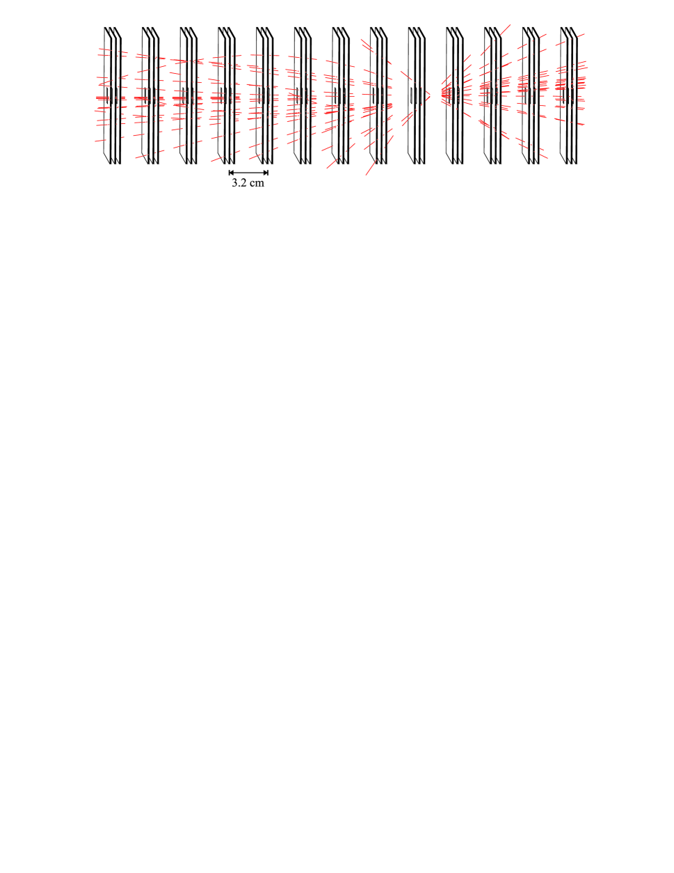
BTeV includes detectors (see FIG. 1) featured in many collider experiments, with inner and outer tracking systems, E&M calorimetry, and muon detection. BTeV also includes a Ring Imaging Cherenkov (RICH) counter in each arm of the spectrometer. The RICH detectors are ideal for charged-hadron identification, so that different types of decays can be distinguished from one another. The spectrometer has inner and outer tracking systems that are highly segmented. The inner tracking system, used for precision tracking and vertex reconstruction, is the “centerpiece” of the BTeV spectrometer, and it consists of planar pixel arrays located inside the Tevatron beam vacuum. FIG. 2 shows a close-up view of 13 out of a total of 31 inner tracking stations. In our baseline design the inner tracking system consists of silicon pixel detectors; however, diamond pixel detectors are also being considered.
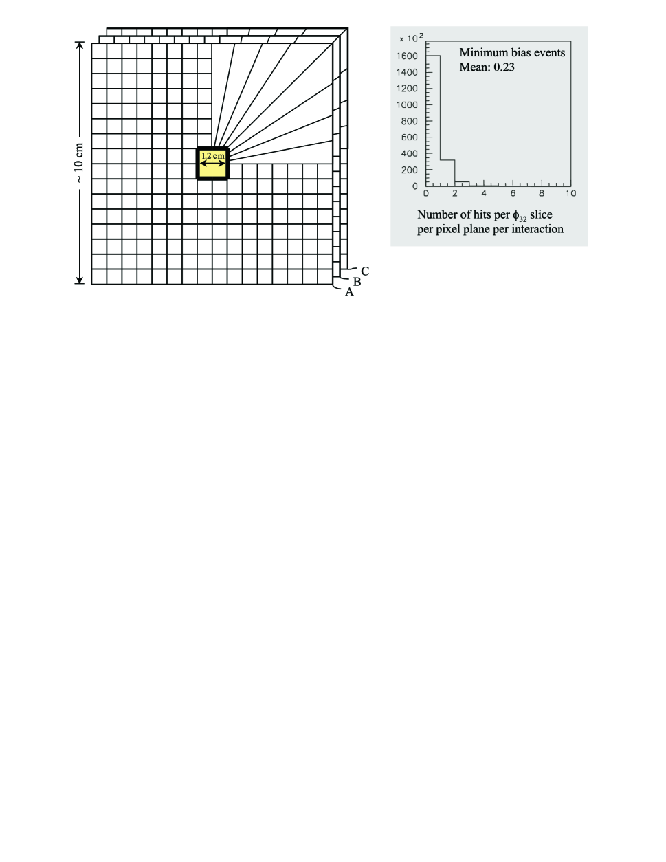
The inner tracker/vertex detector is a key component of the BTeV spectrometer. There are 31 pixel tracking stations. In the central part of the vertex detector the tracking stations are separated by 3.2 cm (center-to-center); at the outer ends of the vertex detector the spacing for 8 of the 31 tracking stations is increased, and the total length of the detector is 128 cm. Each station has three pixel planes that are arranged in views [3] with respect to the magnetic field. There are two bend views and one non-bend view. Each pixel plane has over 500,000 pixels in a 10 x 10 cm area, excluding the beam region. Each pixel provides an X and Y position measurement, and a pulse-height measurement. The pixels, which are 50 x 400 in size, are arranged on sensor chips that are tiled to provide close to 100 coverage over the active area of the vertex detector. FIG. 3 shows a diagram of sensor chips for three quadrants of a pixel plane, and shows the 1.2 x 1.2 cm beam hole at the center of the vertex detector [4]. The beam hole is larger during injection of the Tevatron beams, and is brought into the configuration shown in FIG. 3 after the beams have stabilized.
III Level 1 Trigger
The Level 1 trigger selects events by detecting the presence of decays. These decays are detected by first reconstructing primary interaction vertices. Tracks from decays are then found with an impact parameter cut that selects the tracks that miss the primary vertex by a significant amount. To accomplish these tasks quickly, the Level 1 trigger hardware receives data directly from the pixel detectors (at a rate of 100 Gb/sec). The trigger itself consists of three stages. The first stage is the segment finder, where hits from the three pixel planes per tracking station are assembled into 3-dimensional space points, each with a track-direction mini-vector. These mini-vectors are used for track reconstruction in the second stage of the Level 1 trigger. In the third stage, the reconstructed tracks are used to reconstruct primary interaction vertices, calculate impact parameters, and select tracks coming from secondary vertices.
The Level 1 trigger is heavily pipelined throughout the 3-stage reconstruction process, and performs many operations in parallel to accommodate the data flow from the pixel detectors. Data from an individual pixel consists of an X and Y position measurement, a pulse height measurement, and a time stamp (in units of 132 ns) that is used by the trigger to assemble all of the data belonging to a particular beam crossing. Data from adjacent pixels are combined into a pixel hit by a clustering algorithm that uses pulse height and position measurements. Pixel hits are processed in parallel, for each pixel station, by the segment finder. Additional parallelism is obtained by subdividing pixel hits into slices (see Section IV). The hits for each station are combined into groups of three hits (one from each of three pixel planes), and are used to calculate a 3-dimensional space point and a track-direction mini-vector. FIG. 2 shows a schematic representation of the mini-vectors found for a simulated event. The red line segments, which appear to penetrate each tracking station, represent the mini-vectors that are found by the first stage of the Level 1 trigger.
In the second stage of the trigger, the slope and position measurements for each mini-vector in a pixel station are used to find matching mini-vectors in a neighboring station. Mini-vectors with compatible measurements are combined to form particle trajectories. In the third stage of the trigger, the curvature of these reconstructed trajectories is used to eliminate low momentum tracks, which tend to have large multiple Coulomb scattering errors. We also eliminate tracks with large impact parameters (greater than 2 mm, for example). This reduces the number of incorrect trigger decisions caused by tracks associated with other interactions that occurred during the same beam crossing. The decision to keep or reject the data for a particular beam crossing is based on the number of tracks that are found with a normalized impact parameter () greater than some value. For example, the requirement that there be at least 2 tracks with yields a trigger efficiency of 40 for events [5], while providing a rejection factor of for minimum bias events. This result comes from a simulation of the full pattern recognition with simulated pixel hits, and is presented in greater detail elsewhere [6, 7].
IV Trigger Hardware and Simulations
With 100 gigabytes of pixel data coming into the Level 1 trigger every second, a beam crossing every 132 ns, and an average of 2 interactions per crossing, the time required for each pipeline step in the trigger is critical. Many of the timing issues have been studied by performing a variety of trigger simulations. These include Monte Carlo studies of the pattern recognition and reconstruction algorithms, and simulations of the trigger hardware. The trigger hardware and software algorithms will be extensively tested with a trigger prototype that is being built with components specified in our baseline trigger design. The design utilizes FPGAs (field programmable gate arrays) and two types of DSPs (digital signal processors): a fixed-point DSP, and a floating-point DSP. The fixed-point DSP is made by Texas Instruments and belongs to the TMS320C6X family of DSPs. The floating-point DSP is an Analog Devices ADSP-2106x SHARC. The layout of the logic for the FPGAs is mostly complete. We are currently developing the software algorithms (including optimizations of the code) for the DSPs. I should note that future implementations of the Level 1 trigger may use different DSPs (as new DSPs with better performance are introduced), and that our DSP algorithms will undoubtedly be modified as we optimize the performance of the trigger.
Simulations of the Level 1 baseline design show that the first stage of the trigger, the segment finder, requires the most computational power compared to other parts of the trigger. A large number of operations are performed by the segment finder, due to the number of combinations of pixel hits that must be sampled to find the hits that define a mini-vector. To address this problem, we introduce considerable parallelism in the trigger architecture. This is a key feature of the baseline trigger design. The parallelism begins with the organization of the data read out from the pixel detectors. Pixel hits are read out in parallel for each quadrant of a pixel plane. The hits from the three planes that belong to a pixel station are brought together in a quadrant processor, which represents one of 124 identical circuit boards that make up the first stage of the trigger. Additional parallelism is introduced by subdividing the pixel hits in a quadrant into 8 slices, for a total of 32 slices per pixel station. The hits in each slice are processed in parallel by one of the 992 TMS320C6X DSPs (a total of 992 DSPs for 31 pixel stations, each with 32 -slice DSPs). FIG. 3 shows the “trigger view” of one quadrant, and shows that the subdivision of hits into slices reduces the mean number of hits per pixel plane to a value of 0.23 hits for minimum bias events. This is a small number of hits (on average), and with suitable buffering in the Level 1 trigger we can average over numerous beam crossings in our timing studies.
Even with the small number of hits per slice, the timing for the segment finder is critical. Table I shows timing results for the segment finder algorithm developed for the TMS320C6X DSP. In the table we define four cases to present our results. For a given slice and with three planes (A, B, and C) in a pixel station (as shown in FIG. 3), we have a single hit in each plane for one track passing through a pixel station. This is the (1,1,1) case in Table I. For two tracks passing through the same slice we have two hits per plane, or (2,2,2). With three and four tracks in the same slice we get the (3,3,3) and (4,4,4) cases, respectively. The timing results for the four cases are divided into three categories that represent different levels of optimization for the segment finder algorithm. The first category involves code that has not been optimized (the code is compiled without any optimization), and we use this to establish a reference measurement for subsequent measurements involving different levels of optimization. For the second category we allow the compiler for the TMS320C6X DSP to optimize the algorithm, and for the third case the programming is done directly in assembly language. Although programming in assembly language is more cumbersome, we can optimize the code so that all hardware components in the DSP are performing useful operations most of the time. Our timing results in Table I show that the compiler for the TMS320C6X DSP is not very effective at optimizing the segment finder algorithm; the compiler achieves only a minor performance gain for the (1,1,1) case, and at best a factor of two improvement for cases with more hits in a slice. Table I also shows that we are able to achieve an order of magnitude improvement [8] in the timing by optimizing the algorithm in assembly language.
To obtain an estimate of the average time required to find mini-vectors in minimum bias events, we compute a weighted average by using the results in Table I weighted by the distribution of hits in FIG. 3. We use a value of zero for the (0,0,0) case, since the DSP does not perform any operations when there are no hits in a slice. The average time for each level of optimization is shown in the last row of Table I. Although these results are somewhat oversimplified, they do indicate that an assembly language implementation of the segment finder algorithm is necessary so that the first stage of the trigger stays within a budget of 132 ns per beam crossing. The average time of 37 ns for the segment finder is encouraging, since it suggests that we are close to having a feasible Level 1 trigger design. We continue to work on more refined simulations of the trigger, and on developing the trigger prototype for detailed studies of the trigger hardware.
| Number of hits | Time for | Time for compiler | Time for assember |
|---|---|---|---|
| per slice in | non-optimized | optimized | optimized |
| planes (A,B,C) | segment finder(ns) | segment finder(ns) | segment finder(ns) |
| (1,1,1) | 1915 | 1630 | 135 |
| (2,2,2) | 5705 | 3670 | 315 |
| (3,3,3) | 14015 | 7560 | 1340 [8] |
| (4,4,4) | 28915 | 13840 | 2885 [8] |
| weighted average | 530 | 395 | 37 |
V Alternatives to the Baseline Design
Although most of our trigger-design efforts are devoted to the development of the baseline design of the Level 1 trigger, we are also exploring alternative designs. These alternatives invariably involve design changes in both the Level 1 trigger and the vertex detector, since the two systems are interdependent. For example, we are investigating a design that entails two pixel planes per tracking station instead of the three-plane tracking stations in our baseline design. The two-plane design for the vertex detector has less material, which reduces multiple Coulomb scattering errors. Other advantages include a reduction in the heat load for the pixel cooling system, and perhaps a reduction in cost. These improvements in the vertex detector require significant changes in the Level 1 trigger. The segment finder in the baseline design must be replaced by a different algorithm to initiate the track-reconstruction phase of the trigger. We are working on algorithms that find track segments spanning three tracking stations, compared to the three-plane mini-vectors in the baseline design. In one approach, we are investigating a massively parallel system based on an FPGA design that can handle the large number of pixel-hit combinations that must be sampled to identify three-station track segments. In a second approach, we reduce the number of pixel-hit combinations that must be sampled by finding the first three pixel hits for each track as it passes from the beam region into the vertex detector. In this approach each track is found once, and is then projected to neighboring stations to extend the track and improve the momentum measurement for the track. Both of the alternative trigger designs require additional work before they can be considered as viable alternatives to our baseline trigger design.
VI BTeV Status
BTeV is an approved R&D project. The goal of this project is to conduct all detector R&D, and to design the BTeV experiment. Although the forward-geometry of the BTeV detector offers numerous design challenges, the benefits of a second-generation experiment dedicated to precision studies of physics are substantial. A technical design report will be submitted in 14 months.
REFERENCES
- [1] D. Husby, W. Selove, K. Sterner, P. Chew, NIM A383, 193-198 (1996).
-
[2]
A. Santoro et al., “An Expression of Interest
for a Heavy Quark Program at C0,” May 1997,
http://www-btev.fnal.gov/public_documents/notes/eoi_main.ps. - [3] We define a “view” for a pixel detector as being analogous to the orientation of a silicon strip detector. Since the pixels are rectangular in shape, the long dimension of a pixel is analogous to the long dimension of a silicon strip.
- [4] D.C. Christian et al., “Development of a Pixel Readout Chip for BTeV” FERMILAB-Conf-98/354, to be published in the proceedings of “Vertex ’98, the 7th International Workshop on Vertex Detectors,” Santorini, Greece, September 28–October 4, 1998.
- [5] The trigger efficiency is calculated after requiring that both pions are in the spectrometer and accepted for further analysis.
- [6] J.N. Butler et al., “Status of BTeV – A Dedicated Physics Experiment at the Fermilab Tevatron Collider,” to be published in the proceedings of “The Third International Conference on Hyperons, Charm and Beauty,” Genoa, Italy, June 30–July 3, 1998, http://www-btev.fnal.gov/public_documents/hyperon98.ps.
-
[7]
A. Kulyavtsev et al., presented at XXIX Int’l
Conf. on High Energy Physics, Vancouver, B.C., July 23–29, 1998,
http://www-btev.fnal.gov/public_documents/ichep98.ps. - [8] The assembly language implementation for the (3,3,3) and (4,4,4) cases has not been fully optimized, so an additional improvement in speed is achievable for these cases.