The CLEO-III Ring Imaging Cherenkov Detector
Abstract
The CLEO-III Detector upgrade for charged particle identification is discussed. The RICH design uses solid LiF crystal radiators coupled with multi-wire chamber photon detectors, using TEA as the photosensor, and low-noise Viking readout electronics. Results from our beam test at Fermilab are presented.
HEPSY 99-2Feb. 1999
Invited talk by R. Mountain at “The 3rd International Workshop on Ring Imaging Cherenkov Detectors,” a research workshop of the Israel Science Foundation, Ein-Gedi, Dead-Sea, Israel, Nov. 15-20, 1998
1 INTRODUCTION
The CLEO detector is undergoing a major upgrade (CLEO-III) in conjunction with a luminosity upgrade of the CESR electron-positron collider (CESR Phase-III) [1, 2]. This upgrade will increase the luminosity of the machine by more than a factor of 10, to cm-2sec-1, or 20 fb-1/yr, allowing unprecedented sensitivity to study CP violation in charged decays as well as the phenomenology of rare decay modes (with ). Charged hadron identification is crucial in distinguishing these decay modes. Typically, one wants highly efficient separation with mis-identification probabilities over the full momentum range of secondaries from -hadrons produced at the resonance. Achieving this capability in modern particle detection has heretofore been elusive.
We at CLEO believe that the best way to accomplish this task is to construct a Ring Imaging Cherenkov (RICH) Detector.
2 GENERAL PRINCIPLES OF A PROXIMITY-FOCUSED RICH
The CLEO-III RICH detector consists of three components: radiator, expansion volume, and photon detector. No focusing is used; this is called “proximity-focusing” [3]. When an incident charged particle with sufficient momentum () passes through a radiator medium, it emits photons at an angle via the Cherenkov effect; some photons are internally reflected due to the large refractive index of the radiator, and some escape. These latter photons propagate in a transparent expansion volume, sufficiently large to allow the Cherenkov cone to expand in size (as much as other spatial constraints allow). The photons are imaged by a two-dimensional pad detector, a photosensitive multi-wire chamber which records their spatial position. The resulting images are portions of conic sections, distorted by refraction and truncated by internal reflection at the boundaries of media with different optical densities. Thus, knowing the track parameters of the charged particle and the refractive index of the radiator, one can reconstruct the Cherenkov angle and extract the particle mass.
In order to achieve efficient particle identification with low fake rates, we set as a design goal a system capable of separation with 4 significance () at 2.65 GeV/, the mean maximum momentum for two-body -decays at a symmetric collider. At this momentum, the - Cherenkov angle difference mrad, which along with identification from the central Drift Chamber, requires a Cherenkov angle resolution mrad per track. Using the relation , we can establish round-number benchmarks for our design: a resolution of 14 mrad per photoelectron [7], and a photoelectron yield of 12 pe per track.
3 BASIC DETECTOR DESIGN
The overall RICH design is cylindrical, with compact photon detector modules at the outer radius and radiator crystals at the inner radius, forming thirty 12∘ sectors in azimuth. A schematic of the RICH is given in Ref. [1]. The RICH resides between the central Drift Chamber and the CsI Calorimeter. The ensuing space budget constrains the detector to fit in 80–100 cm in radius, and 2.5 m in length (82% of the solid angle). The mass budget restricts the thickness to 12% to avoid significantly degrading the performance of the Calorimeter.
However, the driving constraint of the design in many respects is the choice of Triethylamine (TEA) as a photosensor, which is both chemically aggressive and manifests a quantum efficiency in the VUV regime (135–165 nm). This greatly restricts the available materials: optical materials must be transparent in the VUV, and construction materials need to be chemically resistant to TEA and low outgassing.
Each detector component and related design issues are discussed in turn.
4 CRYSTAL RADIATORS
The baseline design for the radiator is an array of individual planar LiF crystals111The LiF and CaF2 crystals are grown and polished by OPTOVAC, North Brookfield, MA., each mm2 and 10 mm thick, mounted on an inner carbon fiber cylinder. Due to the high refractive index of LiF ( at 150 nm), a large number of Cherenkov photons are internally reflected, resulting in only a partial ring being imaged (about 1/3 of the initial cone). This is especially severe for incident track angles under 15∘, where the radiator would have to be tilted on the inner cylinder for the incident track to exceed this angle.
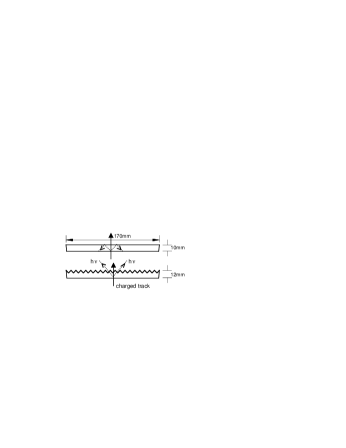
In order to improve this situation, a novel radiator geometry has been implemented [7], cf. Figure 1. This “sawtooth” radiator, with its inner surface cut in profile to resemble the teeth of a saw, allows photons to cross the surface at near normal incidence. This reduces the photon loss by internal reflection and, as a consequence of the refraction angle, also the dominant chromatic error contribution to the resolution. Detailed Monte Carlo simulations [7] indicate that all performance parameters are better with a sawtooth radiator, and especially so at small values of incident track angle. Hence the central region of the detector will use 120 sawtooth radiators (47% of the solid angle coverage), and the outer regions will use 300 planar radiators.
5 EXPANSION VOLUME
The expansion volume is essentially empty space, 157 mm in radial distance, filled with pure N2 gas. There are no support structures in the interior of the detector, which would be obstructions to photon propagation. However structural rigidity must be maintained with low mass, and so our mechanical design calls for aluminum end-flanges glued to the inner cylinder, and a detector module support frame, with reinforcing rib and box structures added to the modules.
Importantly, UV photons will be lost if the expansion volume is not well-sealed from O2 and H2O contamination, and from any possible leakage from the photon detector volume. Redundant gas seals are used in our design, and the N2 will be exchanged at a flow rate sufficient to maintain high transparency.
6 PHOTON DETECTORS
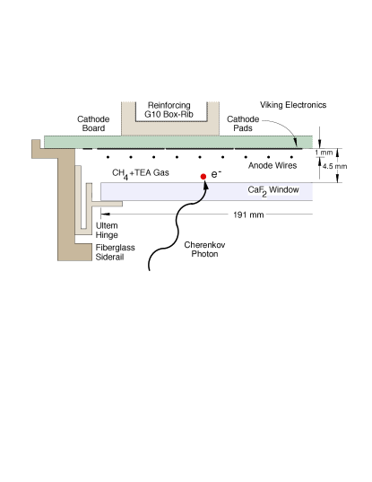
The photon detector is a compact, photosensitive asymmetric multi-wire chamber, shown in Figure 2, filled with CH4 carrier gas bubbled through liquid TEA at 15∘C (5.5% vapor concentration). TEA has a peak QE of 33% at 150 nm and a spectral bandwidth of 135–165 nm [6]. The detection sequence is: a photon passes through a thin UV-transparent CaF2 window and is converted to a single electron by ionizing a TEA molecule. The single photoelectron drifts towards, then avalanches near, the 20 m Ø Au-W anode-wires, and induces a charge signal on the array of mm2 cathode-pads, providing a spatial point for the photoelectron. The design maximizes the photon conversion efficiency by having the wire-window gap be many photoabsorption lengths (%, with mm at 150 nm), and maximizes the anode-cathode charge coupling () by having the wire-pad gap be as small as practical (1 mm). Both may be optimized at once for a fixed thickness by making the chamber asymmetric.
The CaF2 window crystals must be deposited with metallized traces in order to act as field electrodes. Moreover, the crystals are large ( mm2) and quite thin (2 mm) in order to minimize photon absorption and radiation length, and must be mounted with no mechanical stress to avoid inducing fractures. Our design utilizes Ultem hinges, to which the CaF2 windows are glued, to relieve stresses. All construction materials in the chamber volume must be low outgassing and TEA-compatible. Extensive tests of TEA effects on various materials and adhesives of interest have been made.
7 READOUT ELECTRONICS
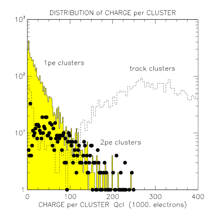
The choice of readout electronics is governed by the Furry (exponential) charge distribution of a single photoelectron avalanche, cf. Figure 3, and also by the time allowed for the readout. The most likely charge is zero, but the tail is long, and so it is necessary to have analog front-end electronics with low noise and large dynamic range in order to maximize the photoelectron detection efficiency. The charge information is necessary in accurately determining the centroid of the photoelectron, as well as in disentangling the overlap of two nearby charge distributions. The latter requires high segmentation. Given the modest pad size over the large detector area, there are 230,400 total electronics channels. Occupancy is low (1%) and so sparsification is required.
The front-end signal processor is the Viking [8] VA_RICH chip, a new custom-designed 64-channel VLSI chip222This Viking chip was designed and manufactured by IDE AS, Oslo, Norway. incorporating these requirements, with measured rms noise ( for modest pF), a shaping time of 1–3 sec, and good linearity up to input. The chip has input protection, a preamplifier/shaper, sample & hold circuitry, and a differential current output multiplexer. The analog signal travels over a 6 m long cable from the detector to a VME databoard with receiver, 12-bit ADC and sparsifier.
8 BEAM-TEST SETUP
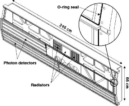
In order to test our understanding of the design and behavior of this detector, a comprehensive beam test was performed. The first two completed photon detectors of the CLEO-III RICH were mounted on an aluminum box simulating the expansion volume, and equipped with one planar and two sawtooth LiF radiators (cf. Figure 4).
The beam test [9] was performed in a muon halo beam in the Meson East area of Fermilab, downstream of Experiment E866. The setup consisted of the RICH itself, its supporting gas and HV systems, trigger scintillators, and a charged-particle tracking system (2 MWPCs with 0.7 mm spatial resolution per station and combined 1 mrad track angle resolution). Data was taken with the RICH box rotated at various polar and azimuthal angles to simulate the different incident track angles expected in CLEO-III.
Photon detector operation was stable during the three week beam test, running at a nominal gain of . The readout for the beam test consisted of 240 VA_RICH chips and 8 VME databoards (for 15360 channels). After common-mode subtraction the remaining incoherent rms noise observed was , providing an average signal-to-noise ratio for photoelectrons of 100:1.
9 BEAM-TEST RESULTS
Photoelectrons (pe) are reconstructed by determining topological clusters of pads with pulse height above a 5 pedestal cut (). The overlap of multiple photoelectrons in a given cluster is disentangled by using the pulse height profile. The unbiased centroid is then found as the location of the photoelectron. (At operating voltage, pad multiplicities are 2.2 pads per cluster, and 1.1 pe per cluster.) From each photoelectron position, the original photon trajectory is optically traced back through all media to the center of the radiator, and the Cherenkov angle is reconstructed. Charged track clusters are distinguished from photon clusters by total charge and by the number of pads in the cluster.
Data has been taken at a variety of track angles; in the following discussion only the datasets for the plane radiator at 30∘ track incidence and for the sawtooth radiator at 0∘ are considered in detail.

Figure 5 shows a cumulative event display for all ring images in these two datasets. For the plane radiator one arc of the Cherenkov ring is visible, while for the sawtooth radiator two arcs in opposition are visible, with the lower one largely outside of the fiducial region of the detectors. Acceptance is lowered by this image truncation, and by mechanical transmission losses from construction elements in the detector. The acceptance for contained plane radiator images is the maximum realistic acceptance for a full RICH system, which is about 85%; the acceptance for sawtooth images is approximately 50% in the two-sector beam test setup.
Results from the analysis of the 30∘ plane radiator dataset are shown in Figure 6; only images confined to a single detector are used. The distribution of Cherenkov angle for single photoelectrons has an asymmetric tail and modest background; it is fit with a Crystal-Ball333The Crystal-Ball lineshape is a Gaussian with an exponential tail at higher angles. Resolution () is extracted from the full-width at half-maximum. lineshape plus polynomial background, yielding a single photoelectron Cherenkov angle resolution mrad with a background fraction of 9.2% under the image and a Monte Carlo estimate of 13.5 mrad. Errors quoted are first statistical then systematic, with the latter taken from two different fitting procedures, i.e., two methods of background estimation. This background is not electronic noise but rather it is principally due to out-of-time hadronic showers from an upstream beam dump; there will be no such background in the CLEO-III running conditions.
The Cherenkov angle per track is found as the arithmetic mean of all photoelectrons in an image. There is an image cut of and a systematic alignment correction applied. The resulting distribution of Cherenkov angle per track is fit to a Gaussian, and gives the angle resolution per track mrad, which compares favorably with the Monte Carlo estimate of 4.45 mrad. The systematic error is estimated from the variation444This variation has a number of root causes, each at the few percent level: the expansion volume transparency was monitored to be above 95%, there are variations in transparency over each radiator face, etc. Hence the systematic error is estimated to be at the 5% level. between different datasets taken at the same track angle, which are repeatable to 5%.
The photoelectron yield pe per track is extracted from the area under the single photoelectron peak followed by background subtraction. Again systematic errors dominate and are given by different methods of background estimation. (Here the beam-test Monte Carlo makes no prediction for but rather uses the measurement as an input parameter.) This yield exceeds our benchmark of 12 pe/track.
 |
 |
 |
Similar analysis for the 0∘ sawtooth radiator dataset, cf. Figure 7, gives a single photoelectron Cherenkov angle resolution mrad with a background fraction of 12.0% (compared with 11.1 mrad from Monte Carlo), an angle resolution per track mrad (4.28 mrad from Monte Carlo), and a photoelectron yield pe/track, background subtracted. Adjusted for full 85% geometric acceptance, becomes 18.8 pe/track.
 |
 |
 |
Figure 8 provides a summary of beam-test results from all datasets at all incident angles. The measured Cherenkov angle resolution per track from the plane radiator data (denoted by squares) increases as a function of the incident track angle due to the increase in emission-point error.555The Cherenkov angle resolution per track is dominated by chromatic and emission-point errors [3]. The chromatic error is larger at small track angles, but they become comparable at large track angles. The beam-test Monte Carlo simulation gives the light dashed curve in Figure 8, which represents the data well.
However the per track resolution, e.g. 4.54 mrad at 30∘, is larger than that naively calculated by statistics, i.e. . Monte Carlo studies indicate that the sources of the increased resolution are the MWPC tracking errors (the principal cause, 2.3 mrad at 30∘) and the beam background (1.2 mrad at 30∘). The tracking errors per se obviously cannot change with rotation of the RICH box, rather they effectively increase the emission-point error due to an incorrect track impact point on the radiator face, and hence become more prominent with track angle. In CLEO-III the background will be much reduced, and the tracking error contribution will be smaller yet still significant.
In order to estimate the ultimate performance of this RICH, an extrapolation was made based on the beam-test Monte Carlo. The background and tracking errors are associated only with our beam test, so both were removed from the simulation for this study. The resulting photoelectron yield was then corrected for the geometric acceptance of the beam-test setup and scaled to “full acceptance”, defined as 85% of the solid angle covered by a cylindrical RICH. The result of this “full acceptance” extrapolation for the per track resolution for the plane radiator is shown as the light solid curve in Figure 8, which is flat in track angle and below our benchmark of 4 mrad for CLEO-III.
The measured per track resolution from the sawtooth radiator data (denoted by circles in Figure 8) also increases with track angle, as expected [7], again due to the increase in emission-point error. However the value of the measured per track resolution is larger than expected. This has several sources: acceptance, MWPC tracking errors, beam background, and sawtooth profile effects. Geometric acceptance is the largest contribution; it is approximately 50% for all track angles. By naive statistical calculation this increases the per track resolution by 35%. Monte Carlo studies show that tracking errors are the next largest contribution (e.g. 1.9 mrad at 0∘), and are exacerbated in this configuration because one of the arcs in the image is out of the detector fiducial. The beam background is approximately constant for all track angles (e.g. 1.3 mrad at 0∘). Sawtooth profile effects are defined as deviations of the real sawtooth radiator from an ideal sawtooth (e.g. rounding of the edges of teeth). However our simulation indicates that profile effects contributes little to the broadening of the resolution since mechanical imperfections are offset by a reduced transmission through the radiator in these same areas.
However even taking into account all these effects the beam-test Monte Carlo, which gives the heavy dashed curve in Figure 8, does not represent the data completely. It consistently underestimates the resolution, indicating that there are additional subtle systematic effects associated with the sawtooth radiator yet to be investigated.
The “full acceptance” extrapolation for the per track resolution for the sawtooth radiator, the heavy solid curve in Figure 8, is flatter in track angle and closer to our expectations in value.
A more sophisticated approach is made in Figure 9, which shows the Cherenkov resolution per track for the 0∘ sawtooth dataset as a function of photoelectron yield. One may read off the per track resolution at the measured yield of 10.4 pe/track and extrapolate to the expected yield of 18.8 pe/track, giving the result as 3.5 mrad. Since this curve is derived from the data it automatically takes into account statistical and systematic effects. Hence we have met our benchmark of 4 mrad.
To summarize, for both plane and sawtooth radiators unfolding the effects of background and tracking error gives angle resolution per track very close to the expected values. The expected CLEO-III RICH performance will fall somewhere between the beam-test Monte Carlo curve and the “full acceptance” curve in Figure 8. Clearly this is sufficient to meet our needs for CLEO-III.


10 CONCLUSIONS and OUTLOOK
A beam test of the first two sectors of the CLEO-III RICH Detector has been successfully carried out. The results obtained fulfill CLEO-III requirements for 4 separation, particularly a Cherenkov angle resolution of about 4 mrad.
The CLEO-III RICH Detector is in the final phase of construction. At present 85% of the photon detectors have been built (with 40% fully tested); all CaF2 windows, 78% of the LiF planar radiators, and 51% of the LiF sawtooth radiators have been delivered; and all readout chips have been acquired and tested. Completion and installation is expected in Summer 1999.
ACKNOWLEDGMENTS
We would like to thank Fermilab for providing us with the dedicated beam time for our test, the Computing Division for its excellent assistance, and our colleagues from E866 for their hospitality in the beamline.
References
- [1] S.E. Kopp, Nucl. Instr. Meth. A384 (1996) 61.
- [2] M. Artuso, “Progress Towards CLEO III”, to be published in the Proceedings of the XXIX International Conference on High Energy Physics, hep-ex/9811031 (1998).
- [3] T. Ypsilantis and J. Séguinot, Nucl. Instr. Meth. A343 (1994) 30.
- [4] R. Arnold et al., Nucl. Instr. Meth. A314 (1992) 465.
- [5] J.-L. Guyonnet et al., Nucl. Instr. Meth. A343 (1994) 178.
- [6] J. Séguinot et al., Nucl. Instr. Meth. A350 (1994) 430.
- [7] A. Efimov et al., Nucl. Instr. Meth. A365 (1995) 285.
- [8] E. Nygard et al., Nucl. Instr. Meth. A301 (1991) 506.
- [9] G. Viehhauser et al., Nucl. Instr. Meth. A419 (1998) 577.