1]INFN, Bologna, Italy 2]Bologna University and INFN, Bologna, Italy 3]CNR-IROE, Florence, Italy
D. Casadei, Diego.Casadei@bo.infn.it
The AMS Time of Flight System
Abstract
The Time of Flight (TOF) system of the AMS experiment provides the fast trigger to the detector and measures the crossing particle direction, velocity and charge. AMS was operated aboard of the shuttle Discovery on June 1998 (NASA STS-91 mission) and will be upgraded and installed on the International Space Station at the end of 2003, for 3 years of data taking. The performances of the TOF during the precursor flight and modifications needed in the final version of the detector are presented.
1 Introduction
The Alpha Magnetic Spectrometer (AMS) (Ahlen et al., 1994) is a particle detector that will be installed on the International Space Station in 2003 to measure cosmic ray fluxes for at least three years.
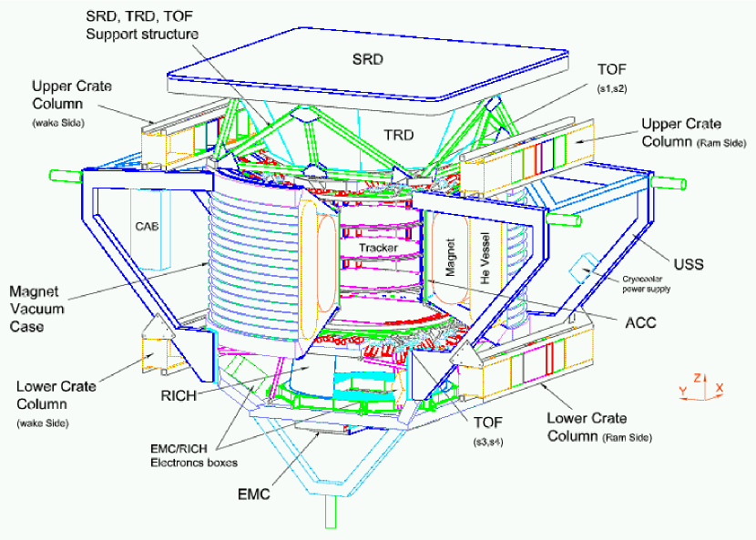
During the precursor flight aboard of the shuttle Discovery (NASA STS-91 mission, 2–12 June 1998), AMS collected data for about 180 hours (AMS Collab., 1999-2000). Figure 1 shows the detector (called AMS-1 in the following), consisting of a permanent Nd-Fe-B magnet, six silicon tracker planes, an anticoincidence scintillator counter system, the time of flight (TOF) system consisting in four layers of scintillator counters and a threshold aerogel Čerenkov detector.
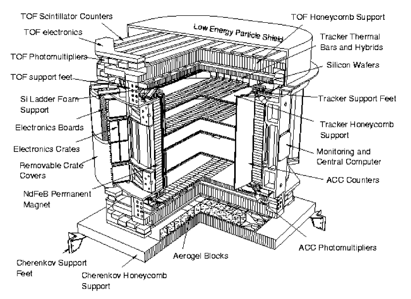
The TOF system (Alvisi et al., 1999) was completely designed and built at the INFN Laboratories in Bologna. Its main goals are to provide the fast trigger to AMS readout electronics, and to measure the particle velocity (), direction, position and charge. In addition, it had to operate in space with severe limits for weight and power consuption.
Each TOF plane consists of 14 scintillator counters covering a roughly circular area of 1.6. The scintillation light is guided to 3 Hamamatsu R5900 photomultipliers per side, whose signals are summed to have a good redundancy and light collection efficiency. The total power consumption of the system (112 channels, 336 phototubes) was 150, while its weight (support structure included) was 250.
2 The AMS-1 trigger
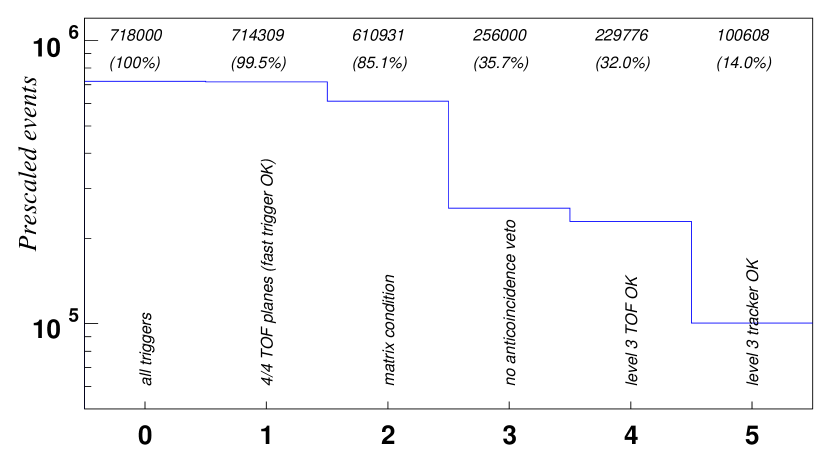
The AMS-1 trigger logic consists of three levels. The fast trigger (FT) processes the analog scintillators data and provides, in about 50, the zero time for the time-of-flight measurement. The first level trigger rejects events with hits on the anticoincidence counter system and enhances the fraction of particles crossing the tracker planes through the analysis of the pattern of hit counters in the first and fourth TOF plane. The second level trigger (nicknamed “third level trigger” for historycal reasons) refines the TOF trigger and finds preliminary tracks on the silicon tracker by using the digitized data.
Figure 2 shows the reduction given by the different trigger conditions on a subsample of data taken requiring only the fast trigger (prescaled events) in the ratio of 1 to 1000 normal triggers.
2.1 Off-time events
The FT signal is generated when at least one counter side in each of the TOF planes produces a signal above a threshold corresponding to 60% of a minimum ionizing particle. To measure the efficiency of this first event selection an unbiased sample of events is required.
This was done by exploiting the characteristics of the TOF read-out electronics to be sensitive to particles impinging in the detector in an interval of about 16 around the trigger signal. Both the (un-discriminated) amplitude and the discriminated output of up to eight hits can be registered by each channel with a time resolution of 1.
In this way off-time particles can be reconstructed in a totally unbiased way. On average, there are off-time events per trigger, depending on the trigger rate.
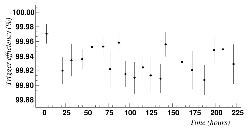
2.2 Fast trigger efficiency and background
The fast trigger efficiency can be derived as the ratio between the number of all off-time particles and the number of off-time particles which produce signals greater than the threshold in all counters hit. Figure 3 shows that this efficiency, for the whole duration of the STS-91 flight111Data taken in the South Atlantic Anomaly are excluded from the analysis., was always above 99.9%.
The background can be estimated by analysing the prescaled events. The ratio between bin 1 and bin 0 of figure 2 shows that only about 0.5% of the fast triggers were due to noise, but this background is completely eliminated by requiring the coincidence of both sides of the same counter in the third level trigger.
3 Time of flight resolution
The single channel time resolution is (Alvisi et al., 1999):
where is the distance of the particle crossing point from the photomultiplier (PM), is the number of photons which convert on the PM window, depends upon the PM signal shape and the trigger electronics, takes into account the dispersion in the photons path lengths and is the electronic noise.
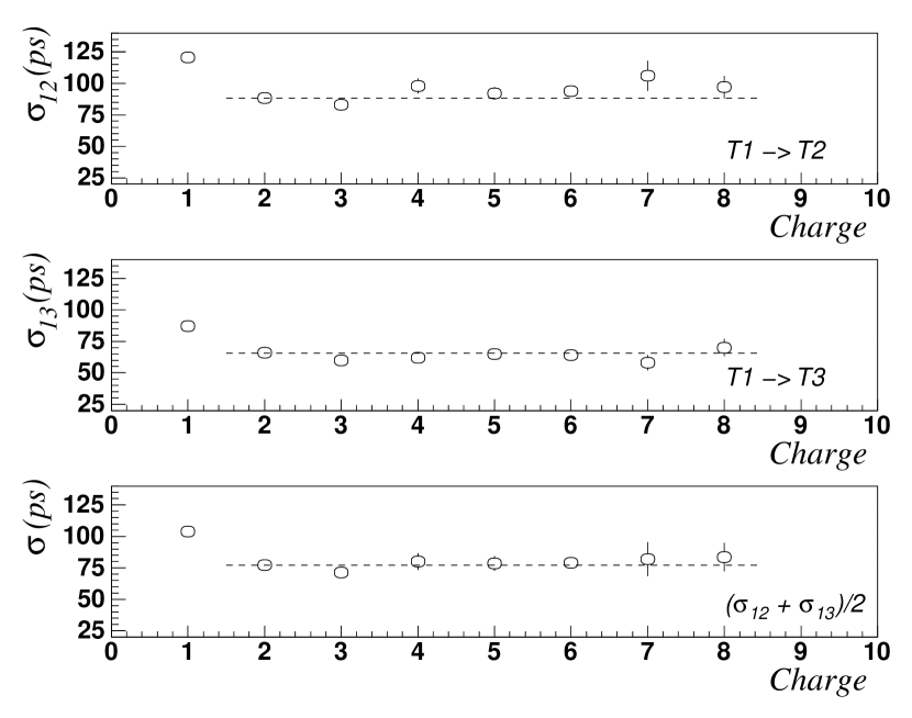
The overall time resolution of a plane can be determined by measuring the time of flight of ultrarelativistic particles between two given planes, after correcting for the track length.
The time dispersion is expected to decrease with the nuclear charge , due to the large number of photoelectrons produced by nuclei with high atomic number, until it reaches the minimum value , dictated by the electronic noise. Figure 4 shows the time resolution measured using the first and the second or the first and the third TOF plane: the horizontal lines show that the level of the electronic noise is 88 for the first measurement and 66 for the second one, leading to a mean value of , which represents the limiting resolution of the system.
4 Photomultipliers stability
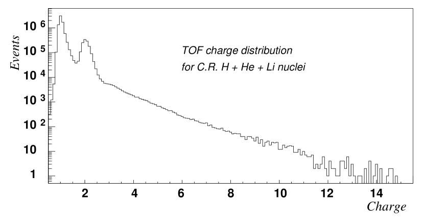
The TOF system provides a measurement of the absolute charge of the crossing particle in addition to the tracker.
Due to the strong constraints about power consuption, the TOF front-end electronics was not optimized for energy deposition measurements. The signal from the PM anodes was integrated and discriminated with a threshold (on the integrated signal) set to about 20% of the minimum ionizing particle. The resulting time-over-threshold is proportional to the logarithm of the deposited charge. The method results in a good separating power between charges and (where is the proton charge) but a poor charge resolution for (see figure 5).
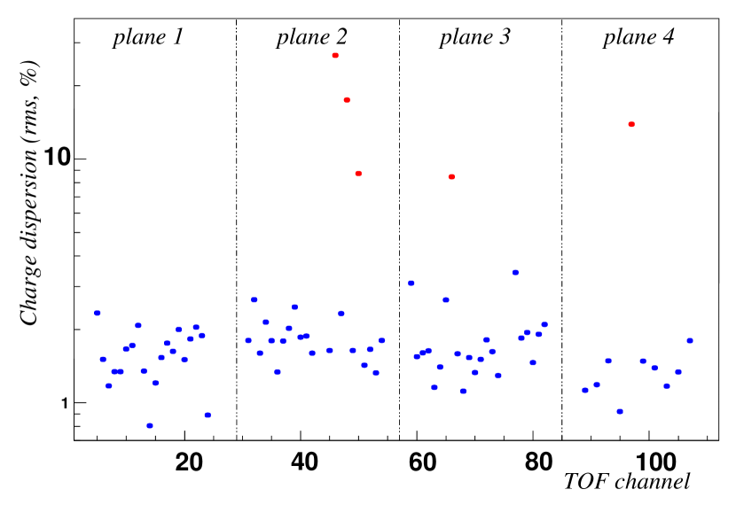
The stability of the charge measurement was very good for all the 112 TOF channels, but five channels, as shown in figure 6.
5 Particle separation
At the trigger level, one goal of the TOF system was to provide a special flag for ions. Accordingly, it was designed to distinguish in a fast and efficient way protons from “” particles.
Even though the low power read-out electronics was not optimized for a good charge measurement, the TOF system energy resolution is sufficient to separate singly by doubly charged particles with a contamination at the level of 1%, as shown in figure 5.
One of the main purpose of the TOF system is the measurement of the time of flight of the particles traversing the detector with a resolution sufficient to distinguish upward from downward going particles: an “upward-going” Helium nucleus wrongly labelled “downward-going” would be interpreted as an “downward-going”anti-Helium nucleus.
The average time of flight of the particles which traverse AMS is of the order of 5, while the time measurement has a resolution , independent from the rigidity. Thus the probability to mistake the particle direction is well below , the level needed for successful operation aboard the ISS, where AMS is expected to collect at least events.
In addition, the velocity resolution of the TOF system, , allows to discriminate between protons and electrons up to a rigidity of 1.5.
6 The time-of-flight system of AMS-2
After the successful operation of AMS-1, the detector has been redesigned to increase the maximum detectable rigidity up to , by using a superconducting magnet which will provide a maximum field of about . Figure 7 shows the new version of the AMS detector (called AMS-2) that will be installed on the ISS at the end of year 2003.
In AMS-1, Hamamatsu R5900 photomultiplier tubes were used as light detectors in that they provided small occupancy, low power consumption and good time resolution. In order to shield the tubes from the residual magnetic field () the PMs were enclosed in a thick shielding case made of VACOFLUX permalloy.
The AMS-2 superconducting magnet produces a much larger field (about ) of variable direction on the TOF planes. To work in such conditions the PMs must withstand the magnetic field without shielding, in a large interval of angles between their axis and the field direction. The design of the TOF system for AMS-2 was therefore completely determined by the choice of the light detectors.
After a market study, the Hamamatsu R5946 photomultiplier tube was considered as the best choice and throughfully tested for time resolution and pulse height response in magnetic field (Brocco et al., 2001). The results show that for angles between the PM axis and the magnetic field greater than about the time resolution of the PMs becomes unacceptably high.
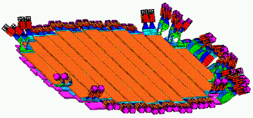
The design of the new TOF counters is different from AMS-1 in the following points: a) due to their larger size, only two PMs are accomodated in each side of the counter; b) the light guides are designed so as they can be tilted to various directions; c) due to mechanical constraints, some of the counters have a clear plastic extension between the scintillator and the light guides.
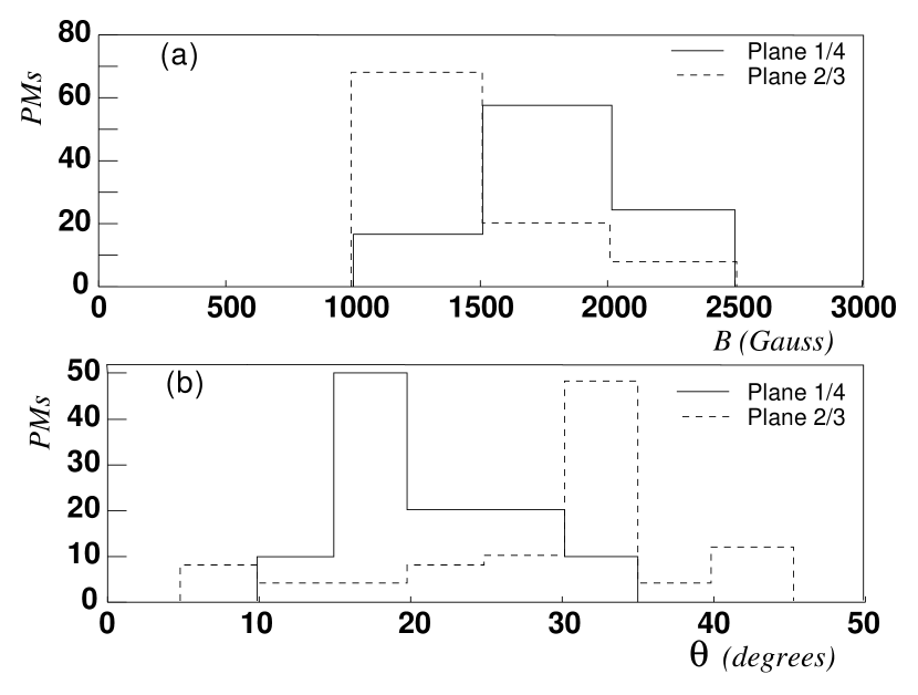
Each of the four TOF planes consists of 12 counters, wide instead of 14 counters ( wide) as in AMS-1. Also, the PM orientations cannot be completely optimized. Figure 8 shows the design of planes 1 and 2 of the TOF system. The PM orientation with respect to the magnetic field and the field magnitude are shown in figure 9 for all PMs of the system.
The read-out electronics presently under design will be similar to AMS-1 as for the time measurement, while the deposited charge will be digitized with linear ADCs in order to reach a better charge resolution.
The AMS-2 TOF system will have a worst time resolution then in AMS-1 ( instead of 120), due to the tilted light guides and to the effect of the magnetic field. In particular, several of the PMs will have an angle with respect to the magnetic field direction greater than .
7 Conclusion
The time of flight system for the AMS detector has proven to be a very efficient triggering system, also capable to discriminate between protons and heavier nuclei with a 1% background, to measure the particle velocity with and the crossing position with , with a total power consumption of about and a weight of 250.
The new version of the subdetector will operate with a very strong residual magnetic field, trying nevertheless to satisfy the same requirements and still keeping power consumption and weight at the same level.
References
- Ahlen et al. (1994) S.P. Ahlen et al., Nuclear Instruments and Methods A 350 (1994) 351.
- AMS Collab. (1999-2000) The AMS Collaboration, Phys. Lett. B 461 (1999) 387-396; Phys. Lett. B 472 (2000) 215-226; Phys. Lett. B 484 (2000) 10-22; Phys. Lett. B 490 (2000) 27-35; Phys. Lett. B 494 (2000) 193-202.
- Alvisi et al. (1999) D. Alvisi et al., Nuclear Instruments and Methods A 437 (1999) 212–221.
- Baldini et al. (2001) L. Baldini et al., “AMS Time of Flight System Performances During the STS-91 Shuttle Flight”, in preparation.
- Brocco et al. (2001) L. Brocco et al., “Photomultipliers Behavior in Strong Magnetic Fields for the TOF System of the AMS-02 Space Experiment”, ICRC2001 (these Proceedings).