The Program in Muon and Neutrino Physics: Super Beams, Cold Muon Beams, Neutrino Factory and the Muon Collider
Chapter 1 Executive Summary
Recent results from the SNO collaboration [1] coupled with data from the SuperK collaboration [2] have provided convincing evidence that neutrinos oscillate and that they very likely do so among the three known neutrino species. Experiments currently under way or planned in the near future will shed further light on the nature of these mixings among neutrino species and the magnitudes of the mass differences between them. Neutrino oscillations and the implied non-zero masses and mixings represent the first experimental evidence of effects beyond the Standard Model, and as such are worthy of our utmost attention.
This document points the way towards establishing an ongoing program of research in accelerator and experimental physics that can be implemented in an incremental fashion. At each step, one opens up new physics vistas, leading eventually to a Neutrino Factory and a Muon Collider. One of the first steps toward a Neutrino Factory is a proton driver that can be used to provide intense beams of conventional neutrinos in addition to providing the intense source of low energy muons from pion decay that must be cooled to be accelerated and stored. While the proton driver is being constructed, we will simultaneously engage in R&D on collecting and cooling muons. A source of intense cold muons can be immediately used to do physics on such items as measuring the electric and magnetic dipole moments of the muon to higher precision, muonium-antimuonium oscillations, rare muon decays and so on. Once we develop the capability of cooling and accelerating muons, the storage ring for such muons will be the first Neutrino Factory. Its precise energy and its distance from the long-baseline experiment will be chosen using the knowledge of neutrino oscillation parameters gleaned from the present generation of solar and accelerator experiments (Homestake, Kamiokande, SuperKamiokande, SAGE, GALLEX, K2K, SNO), the next generation experiments (miniBOONE, MINOS, CNGS, KamLAND, Borexino), and the high-intensity conventional beam experiments that would already have taken place.
A Neutrino Factory provides both and beams of equal intensity for stored beams and their charge conjugate beams for stored beams. Beams from a Neutrino Factory are intense. In addition, they have smaller divergence than conventional neutrino beams of comparable energy. These properties permit the study of non-oscillation physics at near detectors and the measurement of structure functions and associated parameters in non-oscillation physics to unprecedented accuracy. They also permit long-baseline experiments that can determine oscillation parameters to unprecedented accuracy. Depending on the value of the parameter in the three-neutrino oscillation formalism, one can expect to measure the oscillation . By comparing the rates for this channel with its charge-conjugate channel , one can determine the sign of the leading mass difference in neutrinos, , by making use of their passage through matter in a long-baseline experiment. Such experiments can also shed light on the CP violating phase, , in the lepton mixing matrix and enable us to study CP violation in the lepton sector. It is known that CP violation in the quark sector is insufficient to explain the baryon asymmetry of the Universe. Perhaps the lepton sector CP violation plays a crucial role in creating this asymmetry during the initial phases of the Big Bang.
While the Neutrino Factory is being constructed, R&D can be performed to make the Muon Collider a reality. This would require orders of magnitude more cooling. Muon Colliders, if realized, provide a tool to explore Higgs-like objects by direct -channel fusion, much as LEP explored the . They also provide a means to reach higher energies (3–4 TeV in the center of mass) using compact collider rings.
These concepts and ideas have aroused significant interest throughout the world scientific community. In the U.S., a formal collaboration of some 140 scientists, the Neutrino Factory and Muon Collider Collaboration (MC) [3], has undertaken the study of designing a Neutrino Factory, along with R&D activities in support of a Muon Collider design.
1.1 Feasibility Studies
In the fall of 1999, Fermilab, with help from the MC, undertook a Feasibility Study (“Study-I”) of an entry-level Neutrino Factory [4]. One aim of Study-I was to assess the extent to which the Fermilab accelerator complex could be made to evolve into a Neutrino Factory. Study-I showed that such an evolution was clearly possible. The performance reached in Study-I, characterized in terms of the number of muon decays aimed at a detector located 3000 km away from the muon storage ring, was = 2 1019 decays per “Snowmass year” (107 s) per MW of protons on target.
Simultaneously, Fermilab launched a study of the physics that might be addressed by such a facility [5] and, more recently, initiated a study to compare the physics reach of a Neutrino Factory with that of conventional neutrino beams [6] powered by a high intensity proton driver (referred to as “superbeams”). It was determined that a steady and diverse physics program will result from following the evolutionary path from a superbeam to a full-fledged Neutrino Factory.
After the completion of Study-I, BNL organized a follow-on study (“Study-II”) on a high-performance Neutrino Factory sited at BNL, also in collaboration with the MC. An important goal of Study-II was to evaluate whether BNL was a suitable site for a Neutrino Factory. Study-II has recently answered that question affirmatively. A second goal of Study-II was to examine various site-independent means of enhancing the performance of a Neutrino Factory. Based on the improvements in Study-II, the number of muons delivered to the storage ring per Snowmass year from a 1-MW proton driver would be:
where the last factor (0.81) is the estimated efficiency of the acceleration system. For the case of an upgraded 4 MW proton driver, the muon production would increase to 1.4 /year. (R&D to develop a target capable of handling this beam power would be needed.)
The number of muons decaying in the production straight section per Snowmass year would be 35% of this number, or 1.2 1020 decays for a 1 MW proton driver (4.8 1020 decays for a 4 MW proton driver). Though these neutrinos are potentially available for experiments, in the current storage ring design the angular divergence at both ends of the production straight section is higher than desirable for the physics program. This can be improved in a straightforward manner and we are confident that storage ring designs allowing 30–40% of useful muon decays are feasible.
Both Study-I and -II are site specific in that each has a few site-dependent aspects; otherwise, they are generic. In particular, Study-II uses BNL site-specific proton driver specifications corresponding to an upgrade of the 24-GeV AGS complex and a BNL-specific layout of the storage ring, which is housed in an above-ground berm to avoid penetrating the local water table. Study-I uses a new Fermilab booster to achieve its beam intensities and an underground storage ring. The primary substantive difference between the two studies is that Study-II is aimed at a lower muon energy (20 GeV), but higher intensity (for physics reach). Taking the two Feasibility Studies together, we conclude that a high-performance Neutrino Factory could easily be sited at either BNL or Fermilab.
It is worthwhile noting that a storage ring with an average neutrino energy of 15 GeV and useful muon decays will yield (in the absence of oscillations) 30,000 charged-current events in the channel per kiloton-year in a detector located 732 km away. In comparison, a 1.6 MW superbeam [6] from the Fermilab Main Injector with an average neutrino energy of 15 GeV will yield 13,000 charged-current events per kiloton-year. However, a superbeam has a significant contamination, which will be the major background in appearance searches. It is much easier to detect the oscillation from muon storage rings than the oscillation from conventional neutrino beams, since the electron final state from conventional beams has significant background contribution from ’s produced in the events.
1.2 Neutrino Factory Description
The muons we use result from decays of pions produced when an intense proton beam bombards a high-power production target. The target and downstream transport channel are surrounded by superconducting solenoids to contain the pions and muons, which are produced with a larger spread of transverse and longitudinal momenta than can be conveniently transported through an acceleration system. To prepare a beam suitable for subsequent acceleration, we first perform a “phase rotation,” during which the initial large energy spread and small time spread are interchanged using induction linacs. Next, to reduce the transverse momentum spread, the resulting long bunch, with an average momentum of about 250 MeV/, is bunched into a 201.25-MHz bunch train and sent through an ionization cooling channel consisting of LH2 energy absorbers interspersed with rf cavities to replenish the energy lost in the absorbers. The resulting beam is then accelerated to its final energy using a superconducting linac to make the beam relativistic, followed by one or more recirculating linear accelerators (RLAs). Finally, the muons are stored in a racetrack-shaped ring with one long straight section aimed at a detector located at a distance of roughly 3000 km.
A list of the main ingredients of a Neutrino Factory is given below. Details of the design described here are based on the specific scenario of sending a neutrino beam from Brookhaven to a detector in Carlsbad, New Mexico. More generally, however, the design exemplifies a Neutrino Factory for which the two Feasibility Studies demonstrated technical feasibility (provided the challenging component specifications are met), established a cost baseline, and established the expected range of physics performance.
-
•
Proton Driver: Provides 1–4 MW of protons on target from an upgraded AGS; a new booster at Fermilab would perform equivalently.
-
•
Target and Capture: A high-power target immersed in a 20-T superconducting solenoidal field to capture pions produced in proton-nucleus interactions.
-
•
Decay and Phase Rotation: Three induction linacs, with internal superconducting solenoidal focusing to contain the muons from pion decays, that provide nearly non-distorting phase rotation; a “mini-cooling” absorber section is included after the first induction linac to reduce the beam emittance and lower the beam energy to match the cooling channel acceptance.
-
•
Bunching and Cooling: A solenoidal focusing channel, with high-gradient rf cavities and liquid-hydrogen absorbers, that bunches the 250 MeV/ muons into 201.25-MHz rf buckets and cools their transverse normalized emittance from 12 mmrad to 2.7 mmrad.
-
•
Acceleration: A superconducting linac with solenoidal focusing to raise the muon beam energy to 2.48 GeV, followed by a four-pass superconducting RLA to provide a 20 GeV muon beam; a second RLA could optionally be added to reach 50 GeV, if the physics requires this.
-
•
Storage Ring: A compact racetrack-shaped superconducting storage ring in which 35% of the stored muons decay toward a detector located about 3000 km from the ring.
1.3 Detector
The Neutrino Factory plus its long-baseline detector will have a physics program that is a logical continuation of current and near-future neutrino oscillation experiments in the U.S., Japan and Europe. Moreover, detector facilities located in experimental areas near the neutrino source will have access to integrated neutrino intensities – times larger than previously available ( neutrinos per year compared with –).
Specifications for the long-baseline Neutrino Factory detector are rather typical for an accelerator-based neutrino experiment. However, because of the need to maintain a high neutrino rate at these long distances ( 3000 km), the detectors considered here are 3–10 times more massive than those in current neutrino experiments.
Several detector options are possible for the far detector:
-
•
A 50 kton steel–scintillator–proportional-drift-tube (PDT) detector. The PDT detector would resemble MINOS. A detector with dimensions m would record up to events per year.
-
•
A large water-Cherenkov detector, similar to SuperKamiokande but with either a magnetized water volume or toroids separating smaller water tanks. This could be the UNO detector [7], currently proposed to study both proton decay and cosmic neutrinos. UNO would be a 650-kton water-Cherenkov detector segmented into a minimum of three tanks. It would have an active fiducial mass of 440 kton and would record up to events per year from the Neutrino Factory beam.
-
•
A massive liquid-argon magnetized detector [8] that would attempt to detect proton decay, detect solar and supernova neutrinos, and also serve as a Neutrino Factory detector.
For the near detector, a compact liquid-argon TPC (similar to the ICARUS detector [9]) could be used. It would be cylindrically shaped with a radius of 0.5 m and a length of 1 m, would have an active volume of kg, and would provide a neutrino event rate O(10 Hz). The TPC could be combined with a downstream magnetic spectrometer for muon and hadron momentum measurements. At these neutrino intensities, it is even possible to envision an experiment with a relatively thin Pb target (1 ), followed by a standard fixed-target spectrometer containing tracking chambers, time-of-flight and calorimetry, with an event rate O(1 Hz).
1.4 R&D Program
Successful construction of a muon storage ring to provide a copious source of neutrinos requires many novel approaches to be developed and demonstrated. To construct a high-luminosity Muon Collider is an even greater extrapolation of the present state of accelerator design. Thus, reaching the full facility performance in either case requires an extensive R&D program.
Each of the major systems has significant issues that must be addressed by R&D activities, including a mix of theoretical, simulation, modeling, and experimental studies, as appropriate. Component specifications need to be verified. For example, the cooling channel assumes a normal conducting rf (NCRF) cavity gradient of 17 MV/m at 201.25 MHz, and the acceleration section demands similar performance from superconducting rf (SCRF) cavities at this frequency. In both cases, the requirements are beyond the performance reached to date for cavities in this frequency range. The ability of the induction linac units to coexist with their internal SC solenoids must be verified, and the ability of the target to withstand a proton beam power of up to 4 MW must be tested. Finally, some sort of cooling demonstration experiment should be undertaken to validate the implementation of the cooling channel.
To make progress on the R&D program in a timely way, the required support level is about $15M per year. At present, the MC is getting only about $8M per year, so R&D progress is less rapid than it could be.
1.5 Cost Estimate
As part of the Study, we have specified each system in sufficient detail to obtain a “top-down” cost estimate for it. Clearly this estimate is not the complete and detailed cost estimate that would come from preparing a full Conceptual Design Report (CDR). However, there is considerable experience in designing and building accelerators with similar components, so we have a substantial knowledge base from which costs can be derived. With this caveat, we find that the cost of such a facility is about $1.9 B in FY01 dollars. This value represents only direct costs, not including overhead or contingency allowances.
It should be noted that the current design has erred on the side of feasibility rather than costs. Thus, we do not yet have a fully cost-optimized design, nor one that has been reviewed from the standpoint of “value engineering.” In that sense, there is hope that a detailed design study will reduce the costs compared with what we indicate here.
1.6 Staging Scenario
If desired by the particle physics community, a fast-track plan leading directly to a Neutrino Factory could be executed. This would be done by beginning now to create the required Proton Driver (see Stage 1 below), using well-understood technology, while working in parallel on the R&D needed to complete a CDR for the Neutrino Factory facility. We estimate that, with adequate R&D support (see Section 1.4), we could complete a CDR in 2006 and be ready for construction in 2007. On the other hand, the Neutrino Factory offers the distinct advantage that it can be built in stages. This could satisfy both programmatic and cost constraints by allowing an ongoing physics program while reducing the annual construction funding needs. Depending on the results of our technical studies and the results of ongoing searches for the Higgs boson, it is hoped that the Neutrino Factory is really the penultimate stage, to be followed later by a Muon Collider (e.g., a Higgs Factory). Below we list possible stages for the evolution of a muon beam facility and give an indication of incremental costs. These cost increments represent only machine-related items and do not include detector costs.
-
Stage 1: $250–330M (1 MW) or $330–410M (4 MW)
-
We envision a Proton Driver and a Target Facility. The Driver could have a 1 MW beam level or be designed from the outset to reach 4 MW. The Target Facility is built initially to accommodate a 4 MW beam. A 1 MW beam would provide about /s ( /year) and a 4 MW beam about /s ( /year) into a solenoid channel. Costs for this stage depend on site-specific choices, e.g., beam energy. This stage could be accomplished within the next 4–5 years if the particle physics community considers it a high priority.
-
Stage 2: $660–840M
-
We envision a muon beam that has been phase rotated and transversely cooled. This provides a muon beam with a central momentum of about 200 MeV/, a transverse (normalized) emittance of 2.7 mm-rad and an rms energy spread of about 4.5%. The intensity of the beam would be about /s ( /year) at 1 MW, or /s ( /year) at 4 MW. The incremental cost of this option is $840M, based on taking the cooling channel length adopted in Study-II. If more intensity were needed, and if less cooling could be tolerated, the length of the cooling channel could be reduced. Accepting twice the transverse emittance would reduce the incremental cost by about $180M. At this stage, physics with intense cold muon beams can start and continue to the stage when the muons are accelerated.
-
Stage 3: $220–250M
-
We envision using the pre-acceleration Linac to raise the beam energy to roughly 2.5 GeV. The incremental cost of this option is about $220M. At this juncture, it may be appropriate to consider a small storage ring, comparable to the ring at BNL, to be used, perhaps, for the next round of muon experiments. No cost estimate has been made for this ring, but it would be expected to cost roughly $30M.
-
Stage 4: $550M (20 GeV) or $1250–1350M (50 GeV)
-
We envision having a complete Neutrino Factory. For a 20 GeV beam energy, the incremental cost of this stage, which includes the RLA and the storage ring, is $550M. If it were necessary to provide a 50 GeV muon beam for physics reasons, an additional RLA and a larger storage ring would be needed. The incremental cost would then increase by $700–800M.
-
Stage 5
-
We envision an entry-level Muon Collider to operate as a Higgs Factory. No cost estimate has yet been prepared for this stage, so we mention here only the obvious “cost drivers”—the additional cooling and the additional acceleration. Future work will define the system requirements better and permit a cost estimate of the same type provided for Studies-I and -II.
1.7 Muon Collider
As is clear from the above discussion, a Neutrino Factory facility can be viewed as a first critical step on the path toward an eventual high-energy Muon Collider. Such a collider offers the potential of bringing the energy frontier in particle physics within reach of a moderate sized machine. The very fortuitous situation of having an intermediate step along this path that offers a powerful and exciting physics program in its own right presents an ideal opportunity, and it is hoped that the particle physics community will have the resources to take advantage of it.
To reach the feasibility study stage, we must find robust technical solutions to longitudinal emittance cooling, issues related to the high bunch charges, techniques for cooling to the required final emittances, and the design of a very low * collider ring. We are confident that solutions exist along the lines we have been investigating. We in the MC are eager to advance to the stage of building a Muon Collider on the earliest possible time scale. However, for that to happen there is an urgent need to increase support for our R&D so that we can address the vital issues. Unless and until we obtain such support, it is hard to predict how long it will take to solve the longitudinal emittance cooling and other collider-specific problems.
1.8 International Activities
Work on Neutrino Factory R&D is being carried out both in Europe and in Japan. Communication between these groups and the MC is good. In addition to having members of the MC Executive Board from these regions, there are annual NUFACT workshops held to disseminate information. These meetings, which rotate through the three regions, have been held in Lyon (1999), in Monterey (2000), and in Tsukuba (2001); the next meeting will be held in London.
Activities in Europe are centered at CERN but involve many European universities and labs. Their concept for a Neutrino Factory is analogous to that of the MC, but the implementation details differ. The European Proton Driver is based on a 2.2-GeV superconducting proton linac that makes use of the LEP rf cavity infrastructure. Phase rotation and cooling are based on rf cavities operating at 44 and 88 MHz, along with appropriate LH2 absorbers. R&D on the rf cavities is in progress. CERN has mounted the HARP experiment to measure particle yields in the energy regime of interest to them (about 2 GeV). The CERN group is participating actively in the E951 Targetry experiment at BNL, and has provided some of the mercury-jet apparatus that was tested successfully. European groups are also heavily involved in the MUSCAT experiment at TRIUMF, where they play a lead role.
Activities in Japan have concentrated on the development of Fixed-Field Alternating Gradient (FFAG) accelerators. These have very large transverse and longitudinal acceptance, and thus have the potential of giving a Neutrino Factory that does not require cooling. They are pursuing this scheme. A proof-of-principle FFAG giving 500-keV protons has already been built and tested, and plans exist for a 150 MeV version. A 50-GeV 1-MW Proton Driver is approved for construction in Japan, with a six-year schedule. A collaboration with the MC on LH2 absorber design is under way, using U.S.-Japan funds.
On a global note, the three regions are in the process of developing a joint proposal for an international Cooling Demonstration Experiment that could begin in 2004. A Steering Committee has been set up for this purpose, with representatives from all three regions.
1.9 Conclusions
In summary, the Muon Collaboration is developing the knowledge and ability to create, manipulate, and accelerate muon beams. Our R&D program will position the HEP community such that, when it requires a Neutrino Factory or a Muon Collider, we shall be in a position to provide it. A staged plan for the deployment of a Neutrino Factory has been developed that provides an active neutrino and muon physics program at each stage. The requisite R&D program, diversified over laboratories and universities and having international participation, is currently supported at the $8M level, but requires of the order of $15M per year to make progress in a timely way.
Chapter 2 Introduction
2.1 History
The concept of a Muon Collider was first proposed by Budker [10] and by Skrinsky [11] in the 60s and early 70s. However, there was little substance to the concept until the idea of ionization cooling was developed by Skrinsky and Parkhomchuk [12]. The ionization cooling approach was expanded by Neuffer [13] and then by Palmer [14], whose work led to the formation of the Neutrino Factory and Muon Collider Collaboration (MC) [3] in 1995. ***A good summary of the Muon Collider concept can be found in the Status Report of 1999 [15]; an earlier document [16], prepared for Snowmass-1996, is also useful reading. MC Notes prepared by the MC are available on the web [17]
The concept of a neutrino source based on a pion storage ring was originally considered by Koshkarev [18]. However, the intensity of the muons created within the ring from pion decay was too low to provide a useful neutrino source. The Muon Collider concept provided a way to produce a very intense muon source. The physics potential of neutrino beams produced by muon storage rings was investigated by Geer in 1997 at a Fermilab workshop [19, 20] where it became evident that the neutrino beams produced by muon storage rings needed for the muon collider were exciting on their own merit. The neutrino factory concept quickly captured the imagination of the particle physics community, driven in large part by the exciting atmospheric neutrino deficit results from the SuperKamiokande experiment.
As a result, the MC realized that a Neutrino Factory could be an important first step toward a Muon Collider and the physics that could be addressed by a Neutrino Factory was interesting in its own right. With this in mind, the MC has shifted its primary emphasis toward the issues relevant to a Neutrino Factory. There is also considerable international activity on Neutrino Factories, with international conferences held at Lyon in 1999, Monterey in 2000 [21], Tsukuba in 2001 [22], and another planned for London in 2002.
In the fall of 1999, Fermilab undertook a Feasibility Study (“Study-I”) of an entry-level Neutrino Factory [4]. One of the aims of Study-I was to determine to what extent the Fermilab accelerator complex could be made to evolve into a Neutrino Factory. Study-I answered this question affirmatively. Simultaneously Fermilab launched a study of the physics that might be addressed by such a facility [5]. More recently, Fermilab initiated a study to compare the physics reach of a Neutrino Factory with that of conventional neutrino beams [6] powered by a high intensity proton driver, which are referred to as “superbeams”. The aim is to compare the physics reach of superbeams with that of a realistic Neutrino factory. Suffice it to say, it was determined that a steady and diverse stream of physics will result along this evolutionary path.
More recently, BNL organized a follow-on study (“Study-II”) on a high-performance Neutrino Factory sited at BNL. Study-II was recently completed. Clearly, an important goal of Study-II was to evaluate whether BNL was a suitable site for a Neutrino Factory. Based on the work contained in Study-II, that question was answered affirmatively.
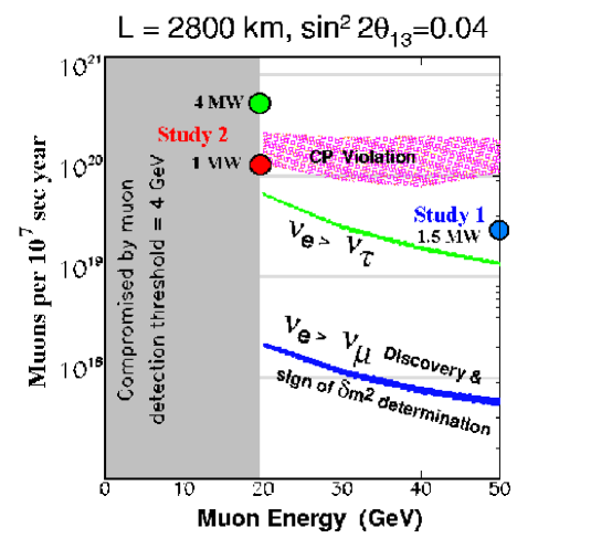
Studies I and II are site specific in that in each study there are a few site-dependent parts; otherwise, they are quite generic. In particular, Study-II uses BNL site-specific proton driver specifications and a BNL-specific layout of the storage ring, especially the pointing angle of the straight sections. Study-I uses an upgraded Fermilab booster to achieve its beam intensities. The primary substantive difference between the two studies is that Study-II is aimed at a lower muon energy (20 GeV), but higher intensity (for physics reach). Figure 2.1 shows a comparison of the performance of the neutrino factory designs in Study I and Study II [5]. Both Study-I and Study-II were carried out jointly with the MC [3], which has over 140 members from many institutions in the U.S. and abroad.
Complementing the Feasibility Studies, the MC carries on an experimental and theoretical R&D program, including work on targetry, cooling, rf hardware (both normal conducting and superconducting), high-field solenoids, LH2 absorber design, theory, simulations, parameter studies, and emittance exchange [23].
2.2 General Scheme and Expected Performance
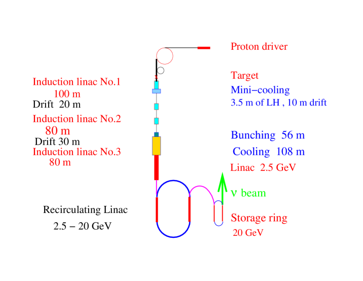
Our present understanding of the design of a Neutrino Factory and results for its simulated performance are summarized here. Specific details can be found in the Study-II report [24]. A schematic layout is shown in Fig.2.2.
2.2.1 Neutrino Factory Systems
In overview, the muons result from decays of pions produced when an intense proton beam bombards a high-power production target. The target and downstream transport channel are surrounded by superconducting solenoids to contain the pions and muons, which are produced with a larger spread of transverse and longitudinal momenta than can be conveniently injected into an acceleration system. To produce a beam suitable for subsequent acceleration, the energy spread is reduced by “phase rotation” where the initial large energy spread and small time spread are interchanged using induction linacs. To reduce the transverse momentum spread, the resulting long bunch, with an average momentum of about 250 MeV/, is bunched into a 201.25 MHz bunch train and then sent through an ionization cooling channel consisting of LH2 energy absorbers interspersed with rf cavities to replenish the energy lost in the absorbers. The resulting beam is then accelerated to its final energy using a superconducting linac to make the beam relativistic, followed by a recirculating linear accelerator (RLA). Finally, the muons are stored in a racetrack-shaped ring with one long straight section aimed at a detector located at a distance of roughly 3000 km.
A list of the main ingredients of a Neutrino Factory is given below; more details can be found in Chapter 4. The details of the design described here are based on the specific scenario of sending a neutrino beam from Brookhaven to a detector in Carlsbad, New Mexico. However, the design exemplifies a general class of Neutrino Factories for which the two Feasibility Studies have 1) demonstrated technical feasibility, 2) established a cost baseline, and 3) established the expected range of physics performance.
-
•
Proton Driver Provides 1 MW of protons on target from an upgraded AGS; a new booster at Fermilab would perform equivalently.
-
•
Target and Capture A mercury-jet target immersed in a 20-T superconducting solenoidal field to capture pions, produced in proton-nucleus interactions. (A technically less-ambitious alternative in which the target is made of graphite has also been considered.)
-
•
Decay and Phase Rotation Three induction linacs, with internal superconducting solenoidal focusing, to contain the muons from pion decays and provide nearly non-distorting phase rotation; a “minicooling” absorber section is included after the first induction linac.
-
•
Bunching and Cooling A solenoidal focusing channel, with high-gradient rf cavities and liquid-hydrogen absorbers, that bunches the 250 MeV/ muons into 201.25-MHz rf buckets and cools their transverse normalized emittance from 12 mmrad to 2.7 mmrad.
-
•
Acceleration A superconducting linac with solenoidal focusing to raise the muon beam energy to 2.48 GeV, followed by a four-pass superconducting RLA to provide a 20 GeV muon beam; a second RLA could optionally be be added to reach 50 GeV, if the physics requires such high energy.
-
•
Storage Ring A compact racetrack-shaped superconducting storage ring in which 35% of the stored muons decay toward a detector located 2900 km from the ring.
2.2.2 Predicted Performance
Complete simulations up to the start of acceleration have been performed using the code MARS [25] (for pion production) followed by ICOOL [26] (for transport, phase rotation, and cooling). These results have been confirmed by GEANT4 [27]. They show an average of 0.17 final muons per initial proton on the target, i.e., 0.0071 /GeV (considering the energy of the initial beam). This can be compared with a value of 0.0011 /GeV produced in Study-I. The gain compared with Study-I (a factor of 6) comes from:
-
•
Use of mercury, instead of carbon, as a target (1.9)
-
•
Use of three, instead of one, induction linacs for phase rotation (2)
-
•
Use of a more efficient tapered cooling channel design (1.4)
-
•
Use of a larger acceptance for the acceleration channel (1.2)
Based on the improvements from Study-II, the number of muons delivered to the storage ring per Snowmass year (107 s) from a 1-MW proton driver would be:
where the last factor (0.81) is the calculated efficiency of the acceleration system. Note that for the case of an upgraded 4 MW proton driver, the muon production would increase to 1.4 /year. The number of muons decaying in the production straight section per Snowmass year would be 35% of this number, or 1.2 1020 decays for a 1 MW proton driver (4.8 1020 decays for a 4 MW proton driver).
Though these numbers of neutrinos are potentially available for experiments, in the current storage-ring design the angular divergence at both ends of the production straight section is higher than desirable for the physics program. In any case, we anticipate that storage-ring designs that allow 30–40% of the muon decays to provide useful neutrinos are feasible.
It is worthwhile noting that a storage ring with an average neutrino energy of 15 GeV and 21020 useful muon decays will yield (in the absence of oscillations) 30,000 charged current events/kiloton-year in a detector placed 732 km away in the channel. In comparison, a 1.6 MW superbeam [6] from the Fermilab Main Injector with an average neutrino energy of 15 GeV will yield 13,000 charged current events per kiloton-year. However, these superbeams have a significant contamination which will be the major background in appearance searches. It is much easier to detect the oscillation from muon storage rings than the oscillation from conventional neutrino beams, since the electron final state from conventional beams has significant background contribution from ’s produced in the events.
2.3 Outline of Report
In what follows, we give a scenario for a staged approach to constructing a Neutrino Factory and eventually a Muon Collider. Chapter 3 discusses the physics opportunities, starting from conventional “superbeams” and going to cold muon beams, then a Neutrino Factory with its near and far detectors, and finally a Muon Collider. In Chapter 4, we describe the components of a Neutrino Factory, based on the Study-II design. Chapter 5 covers our present concept of an entry-level Higgs Factory Muon Collider. Our present understanding of the costs of a Neutrino Factory and the financial implications of possible staging scenarios will be described in Chapter 6. Before embarking on construction of a Neutrino Factory, an R&D program is needed to address various technical issues. A description of the required program and its budget requirements is presented in Chapter 7. Chapter 7 also describes current thinking about a cooling demonstration experiment that would be carried out as an international effort. Finally, in Chapter 8 we provide a brief overview of the international scope of the R&D effort for intense muon beam accelerators.
Chapter 3 Physics Motivation
In this chapter we cover the physics potential of the neutrino factory accelerator complex, which includes superbeams of conventional neutrinos that are possible using the proton driver needed for the factory, and intense beams of cold muons that become available once the muon cooling and collection systems for the factory are in place. Once the cold muons are accelerated and stored in the muon storage ring, we realize the full potential of the factory in both neutrino oscillation and non-oscillation physics.
Cooling muons will be a learning experience. We hope that the knowledge gained in constructing a neutrino factory can be used to cool muons sufficiently to produce the first muon collider operating as a Higgs factory. We examine the physics capabilities of such a collider, which if realized, will invariably lead to higher energy muon colliders with exciting physics opportunities.
3.1 Neutrino Oscillation Physics
Here we discuss [28] the current evidence for neutrino oscillations, and hence neutrino masses and lepton mixing, from solar and atmospheric data. A review is given of some theoretical background including models for neutrino masses and relevant formulas for neutrino oscillation transitions. We next mention the near-term and mid-term experiments in this area and comment on what they hope to measure. We then discuss the physics potential of a muon storage ring as a neutrino factory in the long term.
3.1.1 Evidence for Neutrino Oscillations
In a modern theoretical context, one generally expects nonzero neutrino masses and associated lepton mixing. Experimentally, there has been accumulating evidence for such masses and mixing. All solar neutrino experiments (Homestake, Kamiokande, SuperKamiokande, SAGE, GALLEX and SNO) show a significant deficit in the neutrino fluxes coming from the Sun [29]. This deficit can be explained by oscillations of the ’s into other weak eigenstate(s), with of the order eV2 for solutions involving the Mikheev-Smirnov-Wolfenstein (MSW) resonant matter oscillations [30]-[32] or of the order of eV2 for vacuum oscillations. Accounting for the data with vacuum oscillations (VO) requires almost maximal mixing. The MSW solutions include one for small mixing angle (SMA) and one for large mixing angle (LMA).
Another piece of evidence for neutrino oscillations is the atmospheric neutrino anomaly, observed by Kamiokande [33], IMB [34], SuperKamiokande [35] with the highest statistics, and by Soudan [36] and MACRO [37]. These data can be fit by the inference of oscillations with eV2 [35] and maximal mixing . The identification is preferred over , and the identification is excluded by both the Superkamiokande data and the Chooz experiment [39].
In addition, the LSND experiment [40] has reported and oscillations with eV2 and a range of possible mixing angles. This result is not confirmed, but also not completely ruled out, by a similar experiment, KARMEN [41]. The miniBOONE experiment at Fermilab is designed to resolve this issue, as discussed below.
If one were to try to fit all of these experiments, then, since they involve three quite different values of , which could not satisfy the identity for three neutrino species,
| (3.1) |
it would follow that one would have to introduce further neutrino(s). Since one knows from the measurement of the width that there are only three leptonic weak doublets with associated light neutrinos, it follows that such further neutrino weak eigenstate(s) would have to be electroweak singlet(s) (“sterile” neutrinos). Because the LSND experiment has not been confirmed by the KARMEN experiment, we choose here to use only the (confirmed) solar and atmospheric neutrino data in our analysis, and hence to work in the context of three active neutrino weak eigenstates.
3.1.2 Neutrino Oscillation Formalism
In this theoretical context, consistent with solar and atmospheric data, there are three electroweak-doublet neutrinos and the neutrino mixing matrix is described by,
| (3.2) |
where , , and . The phases and do not affect neutrino oscillations. Thus, in this framework, the neutrino mixing relevant for neutrino oscillations depends on the four angles , , , and , and on two independent differences of squared masses, , which is in the favored fit, and , which may be taken to be . Note that these quantities involve both magnitude and sign; although in a two-species neutrino oscillation in vacuum the sign does not enter, in the three-species-oscillation, that includes both matter effects and CP violation, the signs of the quantities enter and can, in principle, be measured.
For our later discussion it will be useful to record the formulas for the various neutrino-oscillation transitions. In the absence of any matter effect, the probability that a (relativistic) weak neutrino eigenstate becomes after propagating a distance is
| (3.3) | |||||
where
| (3.4) |
and
| (3.5) |
Recall that in vacuum, CPT invariance implies and hence, for , . For the CP-transformed reaction and the T-reversed reaction , the transition probabilities are given by the right-hand side of (3.3) with the sign of the imaginary term reversed. (Below we shall assume CPT invariance, so that CP violation is equivalent to T violation.)
In most cases there is only one mass scale relevant for long-baseline neutrino oscillations, eV2, and one possible neutrino mass spectrum is the hierarchical one
| (3.6) |
In this case, CP (T) violation effects are negligibly small, so that in vacuum
| (3.7) |
and
| (3.8) |
In the absence of T violation, the second equality (3.8) would still hold in uniform matter, but even in the absence of CP violation, the first equality (3.7) would not hold. With the hierarchy (3.6), the expressions for the specific oscillation transitions are
| (3.9) | |||||
| (3.11) |
| (3.12) | |||||
| (3.14) |
| (3.15) | |||||
| (3.17) |
In neutrino oscillation searches using reactor antineutrinos, i.e. tests of , the two-species mixing hypothesis used to fit the data is
| (3.18) | |||||
| (3.20) |
where is the squared mass difference relevant for . In particular, in the upper range of values of , since the transitions and contribute to disappearance, one has
| (3.21) |
i.e., , and, for the value eV2 from SuperK, the CHOOZ experiment on disappearance yields the upper limit [39]
| (3.22) |
which is also consistent with conclusions from the SuperK data analysis [35].
Further, the quantity “” often used to fit the data on atmospheric neutrinos with a simplified two-species mixing hypothesis, is, in the three-generation case,
| (3.23) |
The SuperK experiment finds that the best fit to their data is to infer oscillations with maximal mixing, and hence and . The various solutions of the solar neutrino problem involve quite different values of and : (i) large mixing angle solution, LMA: eV2 and ; (ii) small mixing angle solution, SMA: and , (iii) LOW: , , and (iv) “just-so”: , . The SuperK experiment favors the LMA solutions [29]; for other global fits, see, e.g., Gonzalez-Garcia et al. [29].
We have reviewed the three neutrino oscillation phenomenology that is consistent with solar and atmospheric neutrino oscillations. In what follows, we will examine the neutrino experiments planned for the immediate future that will address some of the relevant physics. We will then review the physics potential of the Neutrino Factory.
3.1.3 Relevant Near- and Mid-Term Experiments
There are currently intense efforts to confirm and extend the evidence for neutrino oscillations in all of the various sectors – solar, atmospheric, and accelerator. Some of these experiments are running; in addition to SuperKamiokande and Soudan-2, these include the Sudbury Neutrino Observatory, SNO, and the K2K long baseline experiment between KEK and Kamioka. Others are in development and testing phases, such as miniBOONE, MINOS, the CERN - Gran Sasso program, KamLAND, and Borexino [42]. Among the long baseline neutrino oscillation experiments, the approximate distances are km for K2K, 730 km for both MINOS (from Fermilab to Soudan) and the proposed CERN-Gran Sasso experiments.
K2K is a disappearence experiment with a conventional neutrino beam having a mean energy of about 1.4 GeV, going from KEK 250 km to the SuperK detector. It has a near detector for beam calibration. It has obtained results consistent with the SuperK experiment, and has reported that its data disagree by with the no-oscillation hypothesis [38].
MINOS is another conventional neutrino beam experiment that takes a beam from Fermilab 730 km to a detector in the Soudan mine in Minnesota. It again uses a near detector for beam flux measurements and has opted for a low-energy configuration, with the flux peaking at about 3 GeV. This experiment is scheduled to start taking data in early 2004 and, after some years of running, to obtain higher statistics than the K2K experiment and to achieve a sensitivity down to the level eV2.
The CERN - Gran Sasso program will come on later, around 2005. It will use a higher-energy neutrino beam from CERN to the Gran Sasso deep underground laboratory in Italy. This program will emphasize detection of the ’s produced by the ’s that result from the inferred neutrino oscillation transition . The OPERA experiment will do this using emulsions [43], while the ICARUS proposal uses a liquid argon chamber [44].
Plans for the Japan Hadron Facility (JHF), also called the High Intensity Proton Accelerator (HIPA), include the use of a 1 MW proton driver to produce a high-intensity conventional neutrino beam with a pathlength 300 km to the SuperK detector [63]. Moreover, at Fermilab, the miniBOONE experiment is scheduled to start data taking in the near future and to confirm or refute the LSND claim after a few years of running.
There are several relevant solar neutrino experiments. The SNO experiment is currently running and has recently reported their first results that confirm solar neutrino oscillations [1]. These involve measurement of the solar neutrino flux and energy distribution using the charged current reaction on heavy water, . They are expected to report on the neutral current reaction shortly. The neutral current rate is unchanged in the presence of oscillations that involve standard model neutrinos, since the neutral current channel is equally sensitive to all the three neutrino species. If however, sterile neutrinos are involved, one expects to see a depletion in the neutral current channel also.
The KamLAND experiment in Japan is scheduled to begin taking data in late 2001. This is a reactor antineutrino experiment using baselines of 100 - 250 km and will search for disappearance and is sensitive to the solar neutrino oscillation scale. On a similar time scale, the Borexino experiment in Gran Sasso is scheduled to turn on and measure the 7Be neutrinos from the sun. These experiments should help us determine which of the various solutions to the solar neutrino problem is preferred, and hence the corresponding values of and .
This, then, is the program of relevant experiments during the period 2000-2010. By the end of this period, we may expect that much will be learned about neutrino masses and mixing. However, there will remain several quantities that will not be well measured and which can be measured by a neutrino factory.
3.1.4 Oscillation Experiments at a Neutrino Factory
Although a neutrino factory based on a muon storage ring will turn on several years after this near-term period in which K2K, MINOS, and the CERN-Gran Sasso experiments will run, we believe that it has a valuable role to play, given the very high-intensity neutrino beams of fixed flavor-pure content, including, uniquely, and beams in addition to and beams. A conventional positive charge selected neutrino beam is primarily with some admixture of ’s and other flavors from decays(O(1%) of the total charged current rate) and the fluxes of these neutrinos can only be fully understood after measuring the charged particle spectra from the target with high accuracy. In contrast, the potential of the neutrino beams from a muon storage ring is that the neutrino beams would be of extremely high purity: beams would yield 50 % and 50 % , and beams, the charge conjugate neutrino beams. Furthermore, these could be produced with high intensities and low divergence that make it possible to go to longer baselines.
In what follows, we shall take the design values from Study-II of decays per “Snowmass year” ( sec) as being typical. The types of neutrino oscillations that can be searched for with the Neutrino Factory based on the muon storage ring are listed in table 3.1 for the case of which decays to :
| Conventional | Neutrino | ||
| Measurement | Type | beam | Factory |
| survival | * | ||
| appearance | |||
| appearance | |||
| survival | — | ||
| appearance | — | ||
| appearance | — |
It is clear from the processes listed that since the beam contains both neutrinos and antineutrinos, the only way to determine the flavor of the parent neutrino is to determine the identity of the final state charged lepton and measure its charge.
A capability unique to the Neutrino Factory will be the measurement of the oscillation , giving a wrong-sign . Of greater difficulty would be the measurement of the transition , giving a which will decay part of the time to . These physics goals mean that a detector must have excellent capability to identify muons and measure their charges. Especially in a steel-scintillator detector, the oscillation would be difficult to observe, since it would be difficult to distinguish an electron shower from a hadron shower. From the above formulas for oscillations, one can see that, given a knowledge of and that one will have by the time a neutrino factory is built, the measurement of the transition yields the value of .
To get a rough idea of how the sensitivity of an oscillation experiment would scale with energy and baseline length, recall that the event rate in the absence of oscillations is simply the neutrino flux times the cross section. First of all, neutrino cross sections in the region above about 10 GeV (and slightly higher, for production) grow linearly with the neutrino energy. Secondly, the beam divergence is a function of the initial muon storage ring energy; this divergence yields a flux, as a function of , the angle of deviation from the forward direction, that goes like . Combining this with the linear dependence of the neutrino cross section and the overall dependence of the flux far from the production region, one finds that the event rate goes like
| (3.24) |
We base our discussion on the event rates given in the Fermilab Neutrino Factory study [5]. For a stored muon energy of 20 GeV, and a distance of to the WIPP Carlsbad site in New Mexico, these event rates amount to several thousand events per kton of detector per year, i.e. they are satisfactory for the physics program. This is also true for the other pathlengths under consideration, namely km from BNL to Homestake and km to Soudan. A usual racetrack design would only allow a single pathlength , but a bowtie design could allow two different pathlengths (e.g., [61]).
One could estimate that at a time when the neutrino factory turns on, and would be known at perhaps the 20 % level (we emphasize that future projections such as this are obviously uncertain). The neutrino factory will significantly improve precision in these parameters, as can be seen from figure 3.1 which shows the error ellipses possible for a 30 GeV muon storage ring.

In addition the neutrino factory can contribute to the measurement of: (i) , as discussed above; (ii) measurement of the sign of using matter effects; and (iii) possibly a measurement of CP violation in the leptonic sector, if , , and are sufficiently large. To measure the sign of , one uses the fact that matter effects reverse sign when one switches from neutrinos to antineutrinos, and carries out this switch in the charges of the stored . We elaborate on this next.
3.1.5 Matter Effects
With the advent of the muon storage ring, the distances at which one can place detectors are large enough so that for the first time matter effects can be exploited in accelerator-based oscillation experiments. Simply put, matter effects are the matter-induced oscillations which neutrinos undergo along their flight path through the Earth from the source to the detector. Given the typical density of the earth, matter effects are important for the neutrino energy range GeV and eV2 values relevant for the long baseline experiments. Matter effects in neutrino propagation were first pointed out by Wolfenstein [30] and Mikheyev and Smirnov [32]. (See the papers [45]–[60] for details of the MSW effect and its relevance to neutrino factories.) In brief, the transition probabilities in the leading oscillation approximation for propagation through matter of constant density are
| (3.25) | |||||
The oscillation arguments are given by
| (3.26) |
where is given by
| (3.27) |
and
| (3.28) |
| (3.29) |
The amplitude for forward scattering in matter is given by
| (3.30) |
Here is the electron fraction and is the matter density. For neutrino trajectories that pass through the earth’s crust, the average density is typically of order 3 gm/cm3 and . The oscillation probability is directly proportional to , which is approximately proportional to . There is a resonant enhancement for
| (3.31) |
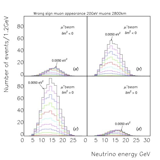
For electron neutrinos, is positive and the resonance enhancement occurs for positive values of for . The reverse is true for electron anti-neutrinos and the enhancement occurs for negative values of . Thus for a neutrino factory operating with positive stored muons (producing a beam) one expects an enhanced production of opposite sign () charged-current events as a result of the oscillation if is positive and vice versa for stored negative beams.
Figure 3.2 [57] shows the wrong-sign muon appearance spectra as function of for both and beams for both signs of at a baseline of 2800 km. The resonance enhancement in wrong sign muon production is clearly seen in Fig. 3.2 (b) and (c).
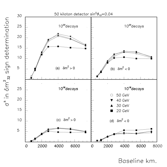
By comparing these (using first a stored beam and then a stored beam) one can thus determine the sign of as well as the value of . Figure 3.3 [57] shows the difference in negative log-likelihood between a correct and wrong-sign mass hypothesis expressed as a number of equivalent Gaussian standard deviations versus baseline length for muon storage ring energies of 20, 30, 40 and 50 GeV. The values of the oscillation parameters are for the LMA scenario with . Figure 3.3(a) is for 1020 decays for each sign of stored energy and a 50 kiloton detector and positive , (b) is for negative for various values of stored muon energy. Figures 3.3 ;(c) and (d) show the corresponding curves for 1019 decays and a 50 kiloton detector. An entry-level machine would permit one to perform a 5 differentiation of the sign of at a baseline length of 2800 km.
For the Study II design, in accordance with the previous Fermilab study [5], one estimates that it is possible to determine the sign of even if is as small as .
3.1.6 CP Violation
CP violation is measured by the (rephasing-invariant) Jarlskog product
| (3.34) | |||||
Leptonic CP violation also requires that each of the leptons in each charge sector be nondegenerate with any other leptons in this sector; this is, course, true of the charged lepton sector and, for the neutrinos, this requires for each such pair . In the quark sector, is known to be small: . A promising asymmetry to measure is . As an illustration, in the absence of matter effects,
| (3.35) | |||||
| (3.37) |
where
| (3.38) |
In order for the CP violation in eq. (3.37) to be large enough to measure, it is necessary that , , and not be too small. From atmospheric neutrino data, we have and . If LMA describes solar neutrino data, then , so . For example, if , then could be . Furthermore, for parts of the LMA phase space where eV2 the CP violating effects might be observable. In the absence of matter, one would measure the asymmetry
| (3.39) |
However, in order to optimize this ratio, because of the smallness of even for the LMA, one must go to large pathlengths , and here matter effects are important. These make leptonic CP violation challenging to measure, because, even in the absence of any intrinsic CP violation, these matter effects render the rates for and unequal since the matter interaction is opposite in sign for and . One must therefore subtract out the matter effects in order to try to isolate the intrinsic CP violation. Alternatively, one might think of comparing with the time-reversed reaction . Although this would be equivalent if CPT is valid, as we assume, and although uniform matter effects are the same here, the detector response is quite different and, in particular, it is quite difficult to identify . Results from SNO and KamLAND testing the LMA will help further planning.
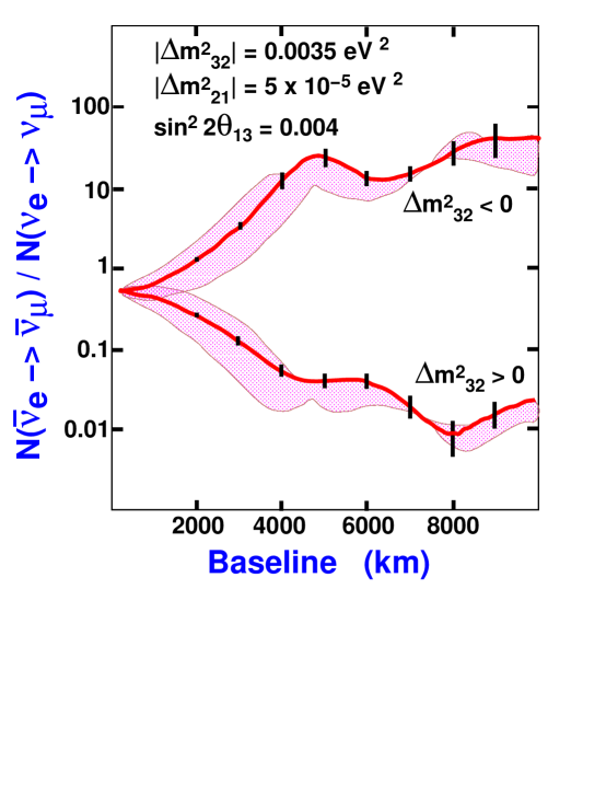
The Neutrino Factory provides an ideal set of controls to measure CP violation effects since we can fill the storage ring with both and particles and measure the ratio of the number of events /. Figure 3.4 shows this ratio for a Neutrino Factory with 1021 decays and a 50 kilo-ton detector as a function of the baseline length. The ratio depends on the sign of . The shaded band around either curve shows the variation of this ratio as a function of the CP violating phase . The number of decays needed to produce the error bars shown is directly proportional to , which for the present example is set to 0.004. Depending on the magnitude of , one may be driven to build a Neutrino Factory just to understand CP violation in the lepton sector, which could have a significant role in explaining the baryon asymmetry of the Universe [62].
3.2 Physics Potential of Superbeams
It is possible to extend the reach of the current conventional neutrino experiments by enhancing the capabilities of the proton sources that drive them. These enhanced neutrino beams have been termed “superbeams” and form an intermediate step on the way to a neutrino factory. Their capabilities have been explored in recent papers [6, 64]. These articles consider the capabilities of enhanced proton drivers at (i) the proposed 0.77 MW 50 GeV proton synchrotron at the Japan Hadron Facility (JHF) [65], (ii) a 4 MW upgraded version of the JHF, (iii) a new MW 16 GeV proton driver [66] that would replace the existing 8 GeV Booster at Fermilab, or (iv) a fourfold intensity upgrade of the 120 GeV Fermilab Main Injector (MI) beam (to 1.6 MW) that would become possible once the upgraded (16 GeV) Booster was operational. Note that the 4 MW 50 GeV JHF and the 16 GeV upgraded Fermilab Booster are both suitable proton drivers for a neutrino factory. The conclusions of both reports are that superbeams will extend the reaches in the oscillation parameters of the current neutrino experiments but “the sensitivity at a neutrino factory to violation and the neutrino mass hierarchy extends to values of the amplitude parameter that are one to two orders of magnitude lower than at a superbeam” [64].
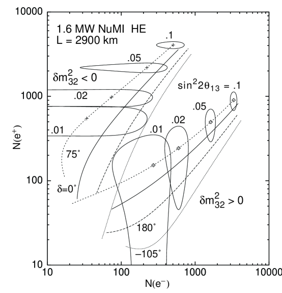
To illustrate these points, we choose one of the most favorable superbeam scenarios studied: a 1.6 MW NuMI–like high energy beam with km, detector parameters corresponding to the liquid argon scenario in [64], and oscillation parameters eV2 and eV2. The calculated three–sigma error ellipses in the –plane are shown in Fig. 3.5 for both signs of , with the curves corresponding to various CP–phases (as labelled). The magnitude of the oscillation amplitude parameter varies along each curve, as indicated. The two groups of curves, which correspond to the two signs of , are separated by more than provided . Hence the mass heirarchy can be determined provided the oscillation amplitude is not less than an order of magnitude below the currently excluded region. Unfortunately, within each group of curves, the CP–conserving predictions are separated from the maximal CP–violating predictions by at most . Hence, it will be difficult to conclusively establish CP violation in this scenario.
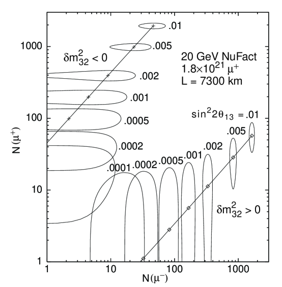
Note for comparison that a very long baseline experiment at a neutrino factory would be able to observe oscillations and determine the sign of for values of as small as O(0.0001) ! This is illustrated in Fig. 3.6. A Neutrino Factory, thus outperforms a conventional superbeam in its ability to determine the sign of . Comparing Fig. 3.5 and Fig. 3.6 one sees that the value of , which has yet to be measured, will determine the parameters of the first neutrino factory.
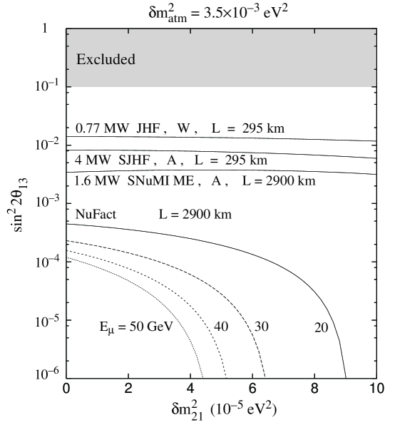
Finally, we compare the superbeam reach with the corresponding neutrino factory reach in Fig. 3.7, which shows the sensitivity contours in the –plane. The superbeam reach of a few is almost independent of the sub–leading scale . However, since the neutrino factory probes oscillation amplitudes the sub–leading effects cannot be ignored, and events would be observed at a neutrino factory over a significant range of even if .
3.3 Non-oscillation physics at a Neutrino Factory
The study of the utility of intense neutrino beams from a muon storage ring in determining the parameters governing non-oscillation physics was begun in 1997 [19]. More complete studies can be found in [5] and recently a European group has brought out an extensive study on this topic [67]. We quote their conclusions here verbatim.
“In the case of determinations of the partonic densities of the nucleon, we proved that the -Factory could significantly improve the already good knowledge we have today. In the unpolarized case, the knowledge of the valence distributions would improve by more than one order of magnitude, in the kinematical region , which is best accessible with 50 GeV muon beams. The individual components of the sea (, , and ), as well as the gluon, would be measured with relative accuracies in the range of 1–10%, for . The high statistics available over a large range of would furthermore allow the accurate determination of higher-twist corrections, strongly reducing the theoretical systematics that affect the extraction of from sum rules and global fits.
“In the case of polarized densities, we stressed the uniqueness of the -Factory as a means of disentangling quark and antiquark distributions, and their first moments in particular. These can be determined at the level of few per cent for up and down, and 10% for the strange, sufficient to distinguish between theoretical scenarios, and thus allowing a full understanding of the proton spin structure. A potential ability to pin down the shapes of individual flavour components with accuracies at the level of few per cent is limited by the mixing with the polarized gluon. To identify this possible weakness of the -Factory polarized-target programme, it was crucial to perform our analysis at the NLO; we showed in fact that any study based on the LO formalism would have resulted in far too optimistic conclusions. This holds true both in the case of determinations based on global fits and on direct extractions using flavour tagging in the final state. Our conclusion here is that a full exploitation of the -Factory potential for polarized measurements of the shapes of individual partonic densities requires an a-priori knowledge of the polarized gluon density. It is hoped that the new information expected to arise from the forthcoming set of polarized DIS experiments at CERN, DESY and RHIC will suffice.
“The situation is also very bright for measurements of C–even distributions. Here, the first moments of singlet, triplet and octet axial charges can be measured with accuracies which are up to one order of magnitude better than the current uncertainties. In particular, the improvement in the determination of the singlet axial charge would allow a definitive confirmation or refutation of the anomaly scenario compared to the ‘instanton’ or ‘skyrmion’ scenarios, at least if the theoretical uncertainty originating from the small– extrapolation can be kept under control. The measurement of the octet axial charge with a few percent uncertainty will allow a determination of the strange contribution to the proton spin better than 10%, and allow stringent tests of models of violation when compared to the direct determination from hyperon decays.
“The measurement of two fundamental constants of nature, and , will be possible using a variety of techniques. At best the accuracy of these measurements will match or slightly improve the accuracy available today, although the measurements at the -Factory are subject to different systematics and therefore provide an important consistency check of current data. In the case of , the dependence of the results on the modeling of higher-twist corrections both in the structure function fits and in the GLS sum rule is significantly reduced relative to current measurements, as mentioned above. In the case of , its determination via scattering at the -Factory has an uncertainty of approximately , dominated by the statistics and the luminosity measurement. This error is comparable to what already known today from EW measurements in decays. Compared to these, however, this determination would improve current low-energy extractions, and be subject to totally different systematic uncertainties. It would also be sensitive to different classes of new-physics contributions. The extrapolation to is affected, at the same level of uncertainty, by the theoretical assumptions used in the evaluation of the hadronic-loop corrections to - mixing. The determination via DIS, on the other hand, is limited by the uncertainties on the heavy-flavour parton densities. As shown earlier, these should be significantly reduced using the -Factory data themselves.
“In several other areas, the data from the -Factory will allow quantitative studies to be made of phenomena that, so far have only been explored at a mostly qualitative level. This is the case of the exclusive production of charmed mesons and baryons (leading to very large samples, suitable for precise extractions of branching ratios and decay constants), of the study of spin-transfer phenomena, and of the study of nuclear effects in DIS. While nuclear effects could be bypassed at the -Factory by using hydrogen targets directly, the flavour separation of partonic densities will require using also targets containing neutrons. This calls for an accurate understanding of nuclear effects. The ability to run with both and heavier targets will in turn provide rich data sets useful for quantitative studies of nuclear models. The study of polarization both in the target and in the fragmentation regions, will help clarifying the intriguing problem of spin transfer. We reviewed several of the existing models, and indicated how semi-inclusive neutrino DIS will allow the identification of the right ones, as well as providing input for the measurement of polarized fragmentation functions.
“Finally, we presented some cases of exploration for physics beyond the SM using the -Factory data. Although the neutrino beam energies considered in our work are well below any reasonable threshold for new physics, the large statistics makes it possible to search for manifestations of virtual effects. The exchange of new gauge bosons decoupled from the first generation of quarks and leptons can be seen via enhancements of the inclusive charm production rate, with a sensitivity well beyond the present limits. Rare lepton-flavour-violating decays of muons in the ring could be tagged in the DIS final states through the detection of wrong-sign electrons and muons, or of prompt taus. Once again, the sensitivity at the -Factory goes well beyond existing limits…”
3.4 Physics that can be done with Intense Cold Muon Beams
Experimental studies of muons at low and medium energies have had a long and distinguished history, starting with the first search for muon decay to electron plus gamma-ray [68], and including along the way the 1957 discovery of the nonconservation of parity, in which the value and magnetic moment of the muon were first measured [69]. The years since then have brought great progress: limits on the standard-model-forbidden decay have dropped by nine orders of magnitude, and the muon anomalous magnetic moment has yielded one of the more precise tests ( ppm) of physical theory, as well as a possible hint of physics beyond the standard model [70].
The front end of a neutrino factory has the potential to provide muons per year, five orders of magnitude beyond the most intense beam currently available.***The E5 beam at PSI, Villigen, providing a maximum rate of muons/s [75]. Such a facility could enable precision measurements of the muon lifetime and Michel decay parameters as well as sensitive searches for lepton-flavor nonconservation (LFV), a possible (- and -violating) muon electric dipole moment (EDM) [71], and and violation in muonic atoms. It could also lead to an improved direct limit on the mass of the muon neutrino [72]. Of these possibilities, Marciano [73] has suggested that muon LFV (especially coherent muon-to-electron conversion in the field of a nucleus) is the “best bet” for discovering signatures of new physics using low-energy muons; measurement of could prove equally exciting but is not yet as well developed, being only at the Letter of Intent stage at present [74].†††Experimentalists might argue that extending such measurements as and the Michel parameters is worthwhile whenever the state of the art allows substantial improvement. However, their comparison with theory is dominated by theoretical uncertainties. Thus, compared to Marciano’s “best bets,” they represent weaker arguments for building a new facility.
The search for is also of great interest. The MEGA experiment recently set an upper limit [76]. Ways to extend sensitivity to the level have been discussed [77]. Sensitivity greater than this may be possible but will be difficult since at high muon rate there will be background due to accidental coincidences; a possible way around this relies on the correlation between the electron direction and the polarization direction using a polarized muon beam. The -to--conversion approach does not suffer from this drawback and has the additional virtue of sensitivity to possible new physics that does not couple to the photon.
In the case of precision measurements (, , etc.), new-physics effects can appear only as small corrections arising from the virtual exchange of new massive particles in loop diagrams. In contrast, LFV and EDMs are forbidden in the standard model, thus their observation at any level constitutes evidence for new physics. The current status and prospects for advances in these areas are summarized in Table 3.2. It is worth recalling that LFV as a manifestation of neutrino mixing is suppressed as and is thus entirely negligible. However, a variety of new-physics scenarios predict observable effects. Table 3.3 lists some examples of limits on new physics that would be implied by nonobservation of -to- conversion () at the level [73].
| Test | Current bound | Current prospects | Future |
|---|---|---|---|
| cm | cm? | ? |
| New Physics | Limit |
|---|---|
| Heavy neutrino mixing | |
| Induced coupling | |
| Induced coupling | |
| Compositeness | TeV |
Precision studies of atomic electrons have provided notable tests of QED (e.g. the Lamb shift in hydrogen) and could in principle be used to search for new physics were it not for nuclear corrections. Studies of muonium () are free of such corrections since it is a purely leptonic system. Muonic atoms also can yield new information complementary to that obtained from electronic atoms. A number of possibilities have been enumerated by Kawall et al. [78] and Molzon [79]. As an example we consider the hyperfine splitting of the muonium ground state, which has been measured to 36 ppb [82] and currently furnishes the most sensitive test of the relativistic two-body bound state in QED [78]. The precision could be further improved with increased statistics. The theoretical error is 0.3 ppm but could be improved by higher-precision measurements in muonium and muon spin resonance, also areas in which the Neutrino Factory front end could contribute. Another interesting test is the search for muonium-antimuonium conversion, possible in new-physics models that allow violation of lepton family number by two units. The current limit is [80], where is the new-physics coupling constant and is the Fermi coupling constant. This sets a lower limit of TeV on the mass of a grand-unified dileptonic gauge boson and also constrains models with heavy leptons [83].
3.5 Physics potential of a Low energy Muon Collider operating as a Higgs Factory
Muon colliders [84, 85] have a number of unique features that make them attractive candidates for future accelerators [15]. The most important and fundamental of these derive from the large mass of the muon in comparison to that of the electron. This leads to: a) the possibility of extremely narrow beam energy spreads, especially at beam energies below ; b) the possibility of accelerators with very high energy; c) the possiblity of employing storage rings at high energy; d) the possibility of using decays of accelerated muons to provide a high luminosity source of neutrinos as discussed in section 3.1.4; e) increased potential for probing physics in which couplings increase with mass (as does the SM coupling).
The relatively large mass of the muon compared to the mass of the electron means that the coupling of Higgs bosons to is very much larger than to , implying much larger -channel Higgs production rates at a muon collider as compared to an electron collider. For Higgs bosons with a very small (MeV-scale) width, such as a light SM Higgs boson, production rates in the -channel are further enhanced by the muon collider’s ability to achieve beam energy spreads comparable to the tiny Higgs width. In addition, there is little bremsstrahlung, and the beam energy can be tuned to one part in a million through continuous spin-rotation measurements [86]. Due to these important qualitative difference between the two types of machines, only muon colliders can be advocated as potential -channel Higgs factories capable of determining the mass and decay width of a Higgs boson to very high precision [87, 88]. High rates of Higgs production at colliders rely on substantial Higgs coupling for the Higgs (Higgstrahlung) or Higgs ( fusion) reactions. In contrast, a collider can provide a factory for producing a Higgs boson with little or no coupling so long as it has SM-like (or enhanced) couplings.
Of course, there is a tradeoff between small beam energy spread, , and luminosity. Current estimates for yearly integrated luminosities (using cm-2s-1 as implying ) are: at for beam energy resolutions of , respectively; at , respectively, for . Despite this, studies show that for small Higgs width the -channel production rate (and statistical significance over background) is maximized by choosing to be such that . In particular, in the SM context for this corresponds to .
If the LEP signal is real or if the interpretation of the precision electroweak data as an indication of a light Higgs boson (with substantial coupling) is valid, then both and colliders will be valuable. In this scenario the Higgs boson would have been discovered at a previous higher energy collider (possibly a muon collider running at high energy), and then the Higgs factory would be built with a center-of-mass energy precisely tuned to the Higgs boson mass. The most likely scenario is that the Higgs boson is discovered at the LHC via gluon fusion () or perhaps earlier at the Tevatron via associated production (), and its mass is determined to an accuracy of about 100 MeV. If a linear collider has also observed the Higgs via the Higgs-strahlung process (), one might know the Higgs boson mass to better than 50 MeV with an integrated luminosity of fb-1. The muon collider would be optimized to run at , and this center-of-mass energy would be varied over a narrow range so as to scan over the Higgs resonance (see Fig. 3.8 below).
3.5.1 Higgs Production
The production of a Higgs boson (generically denoted ) in the -channel with interesting rates is a unique feature of a muon collider [87, 88]. The resonance cross section is
| (3.40) |
In practice, however, there is a Gaussian spread () to the center-of-mass energy and one must compute the effective -channel Higgs cross section after convolution assuming some given central value of :
| (3.42) | |||||

It is convenient to express in terms of the root-mean-square (rms) Gaussian spread of the energy of an individual beam, :
| (3.43) |
From Eq. (3.40), it is apparent that a resolution is needed to be sensitive to the Higgs width. Further, Eq. (3.42) implies that for and that large event rates are only possible if is not so large that is extremely suppressed. The width of a light SM-like Higgs is very small (e.g. a few MeV for ), implying the need for values as small as for studying a light SM-like . Fig. 3.8 illustrates the result for the SM Higgs boson of an initial centering scan over values in the vicinity of . This figure dramatizes: a) that the beam energy spread must be very small because of the very small (when is small enough that the decay mode is highly suppressed); b) that we require the very accurate in situ determination of the beam energy to one part in a million through the spin precession of the muon noted earlier in order to perform the scan and then center on with a high degree of stability.
If the has SM-like couplings to , its width will grow rapidly for and its -channel production cross section will be severely suppressed by the resulting decrease of . More generally, any with SM-like or larger coupling will retain a large -channel production rate when only if the coupling becomes strongly suppressed relative to the coupling.
The general theoretical prediction within supersymmetric models is that the lightest supersymmetric Higgs boson will be very similar to the when the other Higgs bosons are heavy. This ‘decoupling limit’ is very likely to arise if the masses of the supersymmetric particles are large (since the Higgs masses and the superparticle masses are typically similar in size for most boundary condition choices). Thus, rates will be very similar to rates. In contrast, the heavier Higgs bosons in a typical supersymmetric model decouple from at large mass and remain reasonably narrow. As a result, their -channel production rates remain large.
For a SM-like , at GeV and , the rates are
| (3.44) | |||||
| (3.45) |
3.5.2 What the Muon Collider Adds to LHC and LC Data
An assessment of the need for a Higgs factory requires that one detail the unique capabilities of a muon collider versus the other possible future accelerators as well as comparing the abilities of all the machines to measure the same Higgs properties. Muon colliders and a Higgs factory in particular would only become operational after the LHC physics program is well-developed and quite possibly after a linear collider program is mature as well. So one important question is the following: if a SM-like Higgs boson and, possibly, important physics beyond the Standard Model have been discovered at the LHC and perhaps studied at a linear collider, what new information could a Higgs factory provide?
The -channel production process allows one to determine the mass, total width, and the cross sections for several final states to very high precision. The Higgs mass, total width and the cross sections can be used to constrain the parameters of the Higgs sector. For example, in the MSSM their precise values will constrain the Higgs sector parameters and (where is the ratio of the two vacuum expectation values (vevs) of the two Higgs doublets of the MSSM). The main question is whether these constraints will be a valuable addition to LHC and LC constraints.
The expectations for the luminosity available at linear colliders has risen steadily. The most recent studies assume an integrated luminosity of some fb-1 corresponding to 1-2 years of running at a few fb-1 per year. This luminosity results in the production of greater than Higgs bosons per year through the Bjorken Higgs-strahlung process, , provided the Higgs boson is kinematically accessible. This is comparable or even better than can be achieved with the current machine parameters for a muon collider operating at the Higgs resonance; in fact, recent studies have described high-luminosity linear colliders as “Higgs factories,” though for the purposes of this report, we will reserve this term for muon colliders operating at the -channel Higgs resonance.
A linear collider with such high luminosity can certainly perform quite accurate measurements of certain Higgs parameters such as the Higgs mass, couplings to gauge bosons, couplings to heavy quarks, etc. [90]. Precise measurements of the couplings of the Higgs boson to the Standard Model particles is an important test of the mass generation mechanism. In the Standard Model with one Higgs doublet, this coupling is proportional to the particle mass. In the more general case there can be mixing angles present in the couplings. Precision measurements of the couplings can distinguish the Standard Model Higgs boson from one from a more general model and can constrain the parameters of a more general Higgs sector.
| LHC | LC | ||
| 0.17 | 0.2 |
The accuracies possible at different colliders for measuring and of a SM-like with are given in Table 3.4. Once the mass is determined to about 1 MeV at the LHC and/or LC, the muon collider would employ a three-point fine scan [87] near the resonance peak. Since all the couplings of the Standard Model are known, is known. Therefore a precise determination of is an important test of the Standard Model, and any deviation would be evidence for a nonstandard Higgs sector. For a SM Higgs boson with a mass sufficiently below the threshold, the Higgs total width is very small (of order several MeV), and the only process where it can be measured directly is in the -channel at a muon collider. Indirect determinations at the LC can have higher accuracy once is large enough that the mode rates can be accurately measured, requiring . This is because at the LC the total width must be determined indirectly by measuring a partial width and a branching fraction, and then computing the total width,
| (3.46) |
for some final state . For a Higgs boson so light that the decay mode is not useful, then the total width measurement would probably require use of the decays [92]. This would require information from a photon collider as well as the LC and a small error is not possible. The muon collider can measure the total width of the Higgs boson directly, a very valuable input for precision tests of the Higgs sector.
To summarize, if a Higgs is discovered at the LHC or possibly earlier at the Fermilab Tevatron, attention will turn to determining whether this Higgs has the properties expected of the Standard Model Higgs. If the Higgs is discovered at the LHC, it is quite possible that supersymmetric states will be discovered concurrently. The next goal for a linear collider or a muon collider will be to better measure the Higgs boson properties to determine if everything is consistent within a supersymmetric framework or consistent with the Standard Model. A Higgs factory of even modest luminosity can provide uniquely powerful constraints on the parameter space of the supersymmetric model via its very precise measurement of the light Higgs mass, the highly accurate determination of the total rate for (which has almost zero theoretical systematic uncertainty due to its insensitivity to the unknown value) and the moderately accurate determination of the ’s total width. In addition, by combining muon collider data with LC data, a completely model-independent and very precise determination of the coupling is possible. This will provide another strong discriminator between the SM and the MSSM. Further, the coupling can be compared to the muon collider and LC determinations of the coupling for a precision test of the expected universality of the fermion mass generation mechanism.
3.6 Physics Potential of a High Energy Muon Collider
Once one learns to cool muons, it become possible to build muon colliders with energies of 3 TeV in the center of mass that fit on an existing laboratory site [15, 94]. At intermediate energies, it becomes possible to measure the W mass [95] and the top quark mass [96] with high accuracy, by scanning the thresholds of these particles and making use of the excellent energy resolution of the beams. We consider here further the ability of a higher energy muon collider to scan higher lying Higgs like objects such as the H0 and the A0 in the MSSM that may be degenerate with each other.
3.6.1 Heavy Higgs Bosons
As discussed in the previous section, precision measurements of the light Higgs boson properties might make it possible to not only distinguish a supersymmetric boson from a Standard Model one, but also pinpoint a range of allowed masses for the heavier Higgs bosons. This becomes more difficult in the decoupling limit where the differences between a supersymmetric and Standard Model Higgs are smaller. Nevertheless with sufficiently precise measurements of the Higgs branching fractions, it is possible that the heavy Higgs boson masses can be infered. A muon collider light-Higgs factory might be essential in this process.
In the context of the MSSM, can probably be restricted to within or better if . This includes the range of heavy Higgs boson masses for which discovery is not possible via pair production at a LC. Further, the and cannot be detected in this mass range at either the LHC or LC in production for a wedge of moderate values. (For large enough values of the heavy Higgs bosons are expected to be observable in production at the LHC via their decays and also at the LC.)
A muon collider can fill some, perhaps all of this moderate wedge. If is large the and couplings (proportional to times a SM-like value) are enhanced thereby leading to enhanced production rates in collisions. The most efficient procedure is to operate the muon collider at maximum energy and produce the and (often as overlapping resonances) via the radiative return mechanism. By looking for a peak in the final state, the and can be discovered and, once discovered, the machine can be set to or and factory-like precision studies pursued. Note that the and are typically broad enough that would be adequate to maximize their -channel production rates. In particular, MeV if the decay channel is not open, and GeV if it is. Since is sufficient, much higher luminosity () would be possible as compared to that for required for studying the .
In short, for these moderate – scenarios that are particularly difficult for both the LHC and the LC, the muon collider would be the only place that these extra Higgs bosons can be discovered and their properties measured very precisely.
In the MSSM, the heavy Higgs bosons are largely degenerate, especially in the decoupling limit where they are heavy. Large values of heighten this degeneracy. A muon collider with sufficient energy resolution might be the only possible means for separating out these states. Examples showing the and resonances for and are shown in Fig. 3.9. For the larger value of the resonances are clearly overlapping. For the better energy resolution of , the two distinct resonance peaks are still visible, but become smeared out for .

Once muon colliders of these intermediate energies can be built, higher energies such as 3-4 TeV in the center of mass become feasible. Muon colliders with these energies will be complementary to hadron colliders of the SSC class and above. The background radiation from neutrinos from the muon decay becomes a problem at 3 TeV in the CoM. Ideas for ameliorating this problem have been discussed and include optical stochastic cooling to reduce the number of muons needed for a given luminosity, elimination of straight sections via wigglers or undulators, or special sites for the collider such that the neutrinos break ground in uninhabited areas.
Chapter 4 Neutrino Factory
4.1 Description of Neutrino Factory
In this Chapter we describe the various components of a Neutrino Factory. The details here are taken from the most recent Feasibility Study (Study-II) [24] that was carried out jointly by BNL and the MC. The scheme we follow was outlined in Chapter 1.
4.1.1 Proton Driver
The proton driver considered in Study-II is an upgrade of the BNL Alternating Gradient Synchrotron (AGS) and uses most of the existing components and facilities; parameters are listed in Table 4.1. The existing booster is replaced by a 1.2-GeV superconducting proton linac. The modified layout is shown in Fig. 4.1.
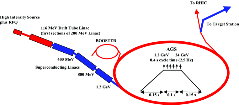
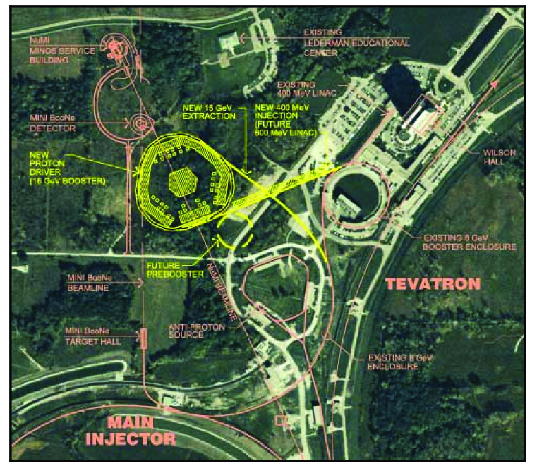
The AGS repetition rate is increased from 0.5 Hz to 2.5 Hz by adding power supplies to permit ramping the ring more quickly. No new technology is required for this—the existing supplies are replicated and the magnets are split into six sectors rather than the two used presently. The total proton charge (1014 ppp in six bunches) is only 40% higher than the current performance of the AGS. Nonetheless, the large increase in peak current argues for an improved vacuum chamber; this is included in the upgrade. The six bunches are extracted separately, spaced by 20 ms, so that the target, induction linacs, and rf systems that follow need only deal with single bunches at an instantaneous repetition rate of 50 Hz (average rate of 15 Hz). The average proton beam power is 1 MW. A possible future upgrade to 2 1014 ppp and 5 Hz could give an average beam power of 4 MW. At the higher intensity, a superconducting bunch compressor ring would be needed to maintain the rms bunch length at 3 ns.
If the facility were built at Fermilab, the proton driver would be a newly constructed 16-GeV rapid cycling booster synchrotron [97]. The planned facility layout is shown in Fig. 4.2. The initial beam power would be 1.2 MW, and a future upgrade to 4 MW would be possible. The Fermilab design parameters are included in Table 4.1. A less ambitious and more cost-effective 8-GeV proton driver option has also been considered for FNAL [97].
| BNL | FNAL | |
| Total beam power (MW) | 1 | 1.2 |
| Beam energy (GeV) | 24 | 16 |
| Average beam current (A) | 42 | 72 |
| Cycle time (ms) | 400 | 67 |
| Number of protons per fill | ||
| Average circulating current (A) | 6 | 2 |
| No. of bunches per fill | 6 | 18 |
| No. of protons per bunch | ||
| Time between extracted bunches (ms) | 20 | 0.13 |
| Bunch length at extraction, rms (ns) | 3 | 1 |
4.1.2 Target and Capture
A mercury jet target is chosen to give a high yield of pions per MW of incident proton power. The 1-cm-diameter jet is continuous, and is tilted with respect to the beam axis. The target layout is shown in Fig. 4.3
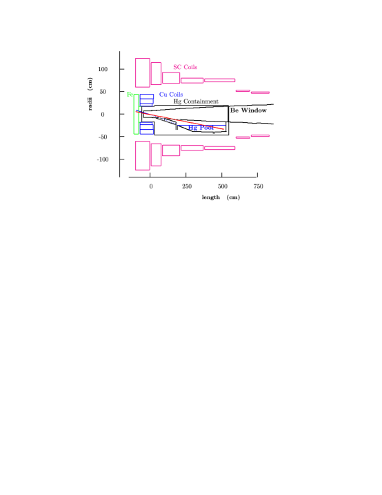
We assume that the thermal shock from the interacting proton bunch fully disperses the mercury, so the jet must have a velocity of 30 m/s to be replaced before the next bunch. Calculations of pion yields that reflect the detailed magnetic geometry of the target area have been performed with the MARS code [98]. To avoid mechanical fatigue problems, a mercury pool serves as the beam dump. This pool is part of the overall target—its mercury is circulated through the mercury jet nozzle after passing through a heat exchanger.
Pions emerging from the target are captured and focused down the decay channel by a solenoidal field that is 20 T at the target center, and tapers down, over 18 m, to a periodic (0.5-m) superconducting solenoid channel ( = 1 .25 T) that continues through the phase rotation to the start of bunching. The 20-T solenoid, with a hollow copper conductor magnet insert and superconducting outer coil, is similar in character to the higher field (up to 45 T), but smaller bore, magnets existing at several laboratories [99]. The magnet insert is made with hollow copper conductor having ceramic insulation to withstand radiation. MARS [98] simulations of radiation levels show that, with the shielding provided, both copper and superconducting magnets could have a lifetime greater than 15 years at 1 MW.
In Study-I, the target was a solid carbon rod. At high beam energies, this implementation has a lower yield than the mercury jet, and is expected to be more limited in its ability to handle the proton beam power, but should simplify the target handling issues that must be dealt with. At lower beam energies, say 6 GeV, the yield difference between C and Hg essentially disappears, so a carbon target would be a competitive option with a lower energy driver. Other alternative approaches, including a rotating Inconel band target, and a granular Ta target are also under consideration, as discussed in Study-II. Clearly there are several target options that could be used for the initial facility.
4.1.3 Phase Rotation
Pions, and the muons into which they decay, are generated in the target over a very wide range of energies, but in a short time pulse (1–3 ns rms). This large energy spread is “phase rotated,” using drifts and induction linacs, into a pulse with a longer time duration and a lower energy spread. The muons first drift and spread out in time, after which the induction linacs decelerate the early ones and accelerate the later ones. Three induction linacs (with lengths of 100, 80, and 80 m) are used in a system that reduces distortion in the phase-rotated bunch, and permits all induction units to operate with unipolar pulses. The 1.25-T beam transport solenoids are placed inside the induction cores to avoid saturating the core material, as shown in Fig. 4.4.
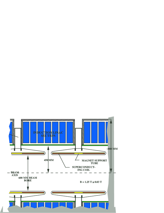
The induction units are similar to those being built for DARHT [100].
Between the first and second induction linacs, two LH2 absorbers (each 1.7 m long and 30 cm radius), with a magnetic field reversal between them, are introduced to reduce the transverse emittance and lower the beam energy to a value matched to the cooling channel acceptance (“mini-cooling”). The beam at the end of the phase rotation section has an average momentum of about 250 MeV/.
4.1.4 Buncher
The long beam pulse (400 ns) after the phase rotation is then bunched at 201.25 MHz prior to cooling and acceleration at that frequency. The bunching is done in a lattice identical to that at the start of the cooling channel, and is preceded by a matching section from the 1.25-T solenoids into this lattice. The bunching has three stages, each consisting of rf (with increasing acceleration) followed by drifts (with decreasing length). In the first two rf sections, second-harmonic 402.5-MHz rf is used together with the 201.25 MHz primary frequency to improve the capture efficiency. The 402.5-MHz cavities are designed to fit into the bore of the focusing solenoids, in the location corresponding to that of the LH2 absorber in the downstream cooling channel.
4.1.5 Cooling
Transverse emittance cooling is achieved by lowering the beam energy in LH2 absorbers, interspersed with rf acceleration to keep the average energy constant. Transverse and longitudinal momenta are lowered in the absorbers, but only the longitudinal momentum is restored by the rf. The emittance increase from Coulomb scattering is minimized by maintaining the focusing strength such that the angular spread of the beam at the absorber locations is large. This is achieved by keeping the focusing strength inversely proportional to the emittance, i.e., increasing it as the emittance is reduced. A modified Focus-Focus (SFOFO) [101] lattice is employed. The solenoidal fields in each cell alternate in sign, and the field shape is chosen to maximize the momentum acceptance ( 22%). To maintain the tapering of the focusing, it was necessary to reduce the cell length from 2.75 m in the initial portion of the channel to 1.65 m in the final portion. A layout of the shorter cooling cell is shown in Fig. 4.5.
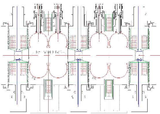
Figure 4.6 shows a simulation of cooling; the emittance falls along the length of the channel. The increase in the number of muons that fit within the acceptance of the downstream acceleration channel is shown in Fig. 4.7.
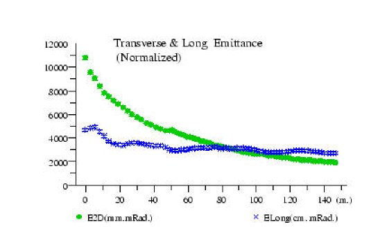
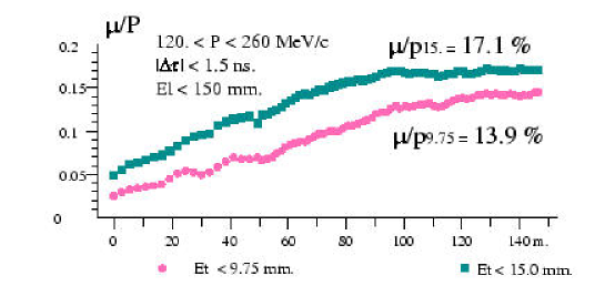
4.1.6 Acceleration
Parameters of the acceleration system are listed in Table 4.2. A 20-m SFOFO matching section, using normal conducting rf systems, matches the beam optics to the requirements of a 2.5 GeV superconducting rf linac with solenoidal focusing. The linac is in three parts. The first part has a single 2-cell rf cavity unit per period. The second part, as a longer period becomes possible, has two 2-cell cavity units per period. The last section, with still longer period, accommodates four 2-cell rf cavity units per period. Figure 4.8 shows the three cryomodule types that make up the linac.
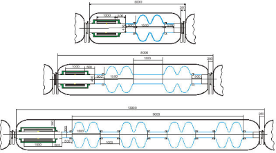
This linac is followed by a single, four-pass recirculating linear accelerator (RLA) that raises the energy from 2.5 GeV to 20 GeV. The RLA uses the same layout of four 2-cell superconducting rf cavity structures as the long cryomodules in the linac, but utilizes quadrupole triplet focusing, as indicated in Fig. 4.9. The arcs have an average radius of 62 m. The final arc has a dipole field of 2 T.
In Study-I, where the final beam energy was chosen to be 50 GeV, a second RLA is needed. This second RLA is similar to the first RLA but considerably larger.
| Injection momentum (MeV/)/Kinetic energy (MeV) | 210/129.4 |
| Final energy (GeV) | 20 |
| Initial normalized acceptance (mm-rad) | 15 |
| rms normalized emittance (mm-rad) | 2.4 |
| Initial longitudinal acceptance, (mm) | 170 |
| momentum spread, | |
| bunch length, (mm) | |
| rms energy spread | 0.084 |
| rms bunch length (mm) | 163 |
| Number of bunches per pulse | 67 |
| Number of particles per bunch/per pulse | / |
| Bunch frequency/accelerating frequency (MHz) | 201.25/ 201.25 |
| Average beam power (kW) | 150 |
4.1.7 Storage Ring
After acceleration in the RLA, the muons are injected into the upward-going straight section of a racetrack-shaped storage ring with a circumference of 358 m. Parameters of the ring are summarized in Table 4.3. High-field superconducting arc magnets are used to minimize the arc length and maximize the fraction (35%) of muons that decay in the downward-going straight and generate neutrinos headed toward the detector located some 3000 km away.
All muons are allowed to decay; the maximum heat load from their decay electrons is 42 kW (126 W/m). This load is too high to be dissipated in the superconducting coils. For Study-II, a magnet design has been chosen that allows the majority of these electrons to pass out between separate upper and lower cryostats, and be dissipated in a dump at room temperature. To maintain the vertical cryostat separation in focusing elements, skew quadrupoles are employed in place of standard quadrupoles. In order to maximize the average bending field, Nb3Sn pancake coils are employed. One coil of the bending magnet is extended and used as one half of the previous (or following) skew quadrupole to minimize unused space. Figure 4.10 shows a layout of the ring as it would be located at BNL. (The existing 110-m-high BNL stack is shown for scale.) For site-specific reasons, the ring is kept above the local water table and is placed on a roughly 30-m-high berm. This requirement places a premium on a compact storage ring.
| Energy (GeV) | 20 |
| Circumference (m) | 358.18 |
| Normalized transverse acceptance (mm-rad) | 30 |
| Energy acceptance (%) | 2.2 |
| Arc | |
| Length (m) | 53.09 |
| No. cells per arc | 10 |
| Cell length (m) | 5.3 |
| Phase advance () | 60 |
| Dipole length (m) | 1.89 |
| Dipole field (T) | 6.93 |
| Skew quadrupole length (m) | 0.76 |
| Skew quadrupole gradient (T/m) | 35 |
| (m) | 8.6 |
| Production Straight | |
| Length (m) | 126 |
| (m) | 200 |
For Study-I, a conventional superconducting ring was utilized to store the 50 GeV muon beam. The heat load from muon decay products in this scenario is managed by having a liner inside the magnet bore to absorb the decay products. This approach is likewise available for BNL, provided some care is taken to keep the ring compact; acceptable solutions have been found for this option as well.
An overall layout of the Neutrino Factory on the BNL site is shown in Fig. 4.11. Figure 4.12 shows the equivalent picture for a facility on the Fermilab site. In this latter case, the layout includes the additional RLA and longer storage ring needed to reach 50 GeV. Clearly the footprint of a Neutrino Factory is reasonably small, and such a machine would fit easily on the site of either BNL or Fermilab.
4.1.8 Detector
The Neutrino Factory, plus its long-baseline detector, will have a physics program that is a logical continuation of current and near-future neutrino oscillation experiments in the U.S., Japan and Europe. Moreover, detector facilities located in experimental areas near the neutrino source will have access to integrated neutrino intensities – times larger than previously available ( neutrinos per year compared with –).
The detector site taken for Study-II is the Waste Isolation Pilot Plant (WIPP) in Carlsbad, New Mexico. The WIPP site is approximately 2900 km from BNL. Space is potentially available for a large underground physics facility at depths of 740–1100 m, and discussions are under way between DOE and the UNO project [7] on the possible development of such a facility.
4.1.8.1 Far Detector
Specifications for the long-baseline Neutrino Factory detector are rather typical for an accelerator-based neutrino experiment. However, because of the need to maintain a high neutrino rate at these long distances, the detectors considered here are 3–10 times more massive than those in current neutrino experiments. Clearly, the rate of detected neutrinos depends on two factors—the source intensity and the detector size. In the actual design of a Neutrino Factory, these two factors must be optimized together.
Two options are considered for the WIPP site: a 50 kton steel–scintillator–proportional-drift-tube (PDT) detector or a water-Cherenkov detector. The PDT detector would resemble MINOS. Figure 4.13 shows a 50-kton detector with dimensions m. A detector of this size would record up to events per year.
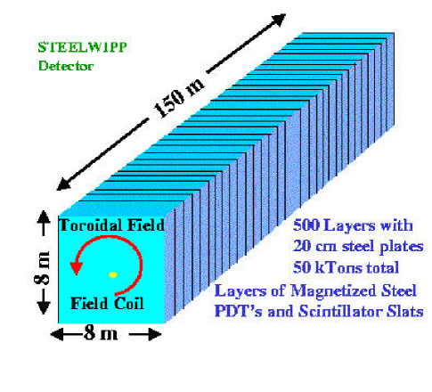
A large water-Cherenkov detector would be similar to SuperKamiokande, but with either a magnetized water volume or toroids separating smaller water tanks. The detector could be the UNO detector [7], currently proposed to study both proton decay and cosmic neutrinos. UNO would be a 650-kton water-Cherenkov detector segmented into a minimum of three tanks (see Fig. 4.14). It would have an active fiducial mass of 440 kton and would record up to events per year from the Neutrino Factory beam.
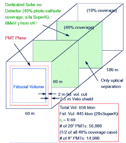
Another proposal for a neutrino detector is a massive liquid-argon magnetized detector [8] that would attempt to detect proton decay, solar and supernova neutrinos as well as serve as a Neutrino Factory detector.
4.1.8.2 Near Detector
As noted, detector facilities located on-site at the Neutrino Factory would have access to unprecedented intensities of pure neutrino beams. This would enable standard neutrino physics studies such as , structure functions, cross sections, nuclear shadowing and pQCD to be performed with much higher precision than previously obtainable. In addition to its primary physics program, the near detector can also provide a precise flux calibration for the far detector, though this may not be critical given the ability to monitor the storage ring beam intensity independently.
A compact liquid-argon TPC (similar to the ICARUS detector [9]), cylindrically shaped with a radius of 0.5 m and a length of 1 m, would have an active volume of kg and a neutrino event rate O(10 Hz). The TPC could be combined with a downstream magnetic spectrometer for muon and hadron momentum measurements. At these intensities, it is even possible to have an experiment with a relatively thin Pb target (1 ), followed by a standard fixed-target spectrometer containing tracking chambers, time-of-flight and calorimetry, with an event rate O (1 Hz).
Chapter 5 Muon Colliders
The lure of muon colliders arises from the fact that the muon is 200 times heavier than the electron and this makes it possible to accelerate the muon using circular accelerators that are compact and fit on existing accelerator sites. See Figure 5.1 for a comparison of relative sizes of muon colliders ranging from 500 GeV to 3 TeV center of mass energies with respect to the LHC, SSC, and NLC. Once we have solved the problem of cooling a muon beam so that it can be accelerated, higher enegies are much more easily obtained in a muon collider than in the linear collider. Because the muon is unstable, it becomes necessary to cool and accelerate it before a substantial number have decayed. With typical bending magnetic fields( 5 Tesla) available with today’s technology, the muons last 1000 turns before half of them have decayed in the collider ring. This is a statement that is independent of the energy of the collider to first order due to relativistic time dilatation.
The muon decay also gives rise to large numbers of electrons that can pose serious background problems for detectors in the collision region. The 1999 Status Report [15] contains an excellent summary of the problems and possible solutions one faces on the way to a muon collider.
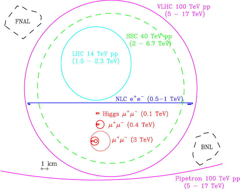
Figure 5.2 shows a schematic of such a muon collider, along with a depiction of the possible physics that can be addressed with each stage of the facility.
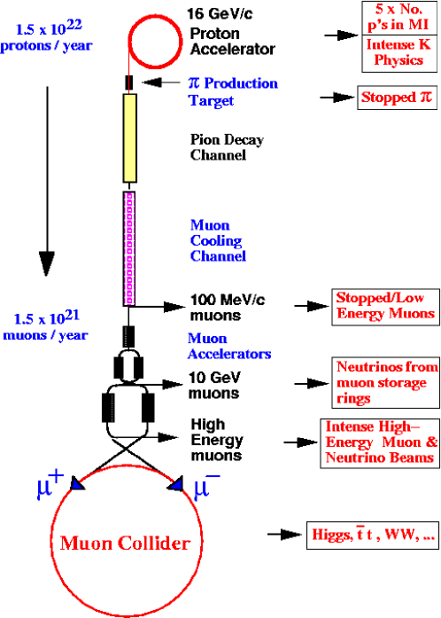
5.1 Higgs Factory Requirements
The emittance of the muon beam needs to be reduced by a factor 106 from production [15] to the point of collision for there to be significant luminosity for experiments. This can be achieved by ionization cooling similar to the scheme described in chapter 4. The transverse emittance is reduced during ionization cooling, since only the longitudinal energy loss is replaced by acceleration. However, due to straggling, the longitudinal emittance grows. In order to cool longitudinally, one exchanges longitudinal and transverse emittances and proceeds to cool the transverse emittance.
The Status report [15] outlines the details of the acceleration and collider ring for the Higgs factory. Table 5.1 gives a summary of the parameters of various muon colliders including three different modes of running the Higgs Collider that have varying beam momentum spreads. Additional information about the Muon Collider can be found at [102, 103].
| CoM energy TeV | 3 | 0.4 | 0.1 | ||
| energy GeV | 16 | 16 | 16 | ||
| ’s/bunch | |||||
| Bunches/fill | 4 | 4 | 2 | ||
| Rep. rate Hz | 15 | 15 | 15 | ||
| power MW | 4 | 4 | 4 | ||
| /bunch | |||||
| power MW | 28 | 4 | 1 | ||
| Wall power MW | 204 | 120 | 81 | ||
| Collider circum. m | 6000 | 1000 | 350 | ||
| Ave bending field T | 5.2 | 4.7 | 3 | ||
| Rms % | 0.16 | 0.14 | 0.12 | 0.01 | 0.003 |
| 6-D | |||||
| Rms mm-mrad | 50 | 50 | 85 | 195 | 290 |
| cm | 0.3 | 2.6 | 4.1 | 9.4 | 14.1 |
| cm | 0.3 | 2.6 | 4.1 | 9.4 | 14.1 |
| spot m | 3.2 | 26 | 86 | 196 | 294 |
| IP mrad | 1.1 | 1.0 | 2.1 | 2.1 | 2.1 |
| Tune shift | 0.044 | 0.044 | 0.051 | 0.022 | 0.015 |
| (effective) | 785 | 700 | 450 | 450 | 450 |
| Luminosity cm-2s-1 | |||||
| Higgs/year | |||||
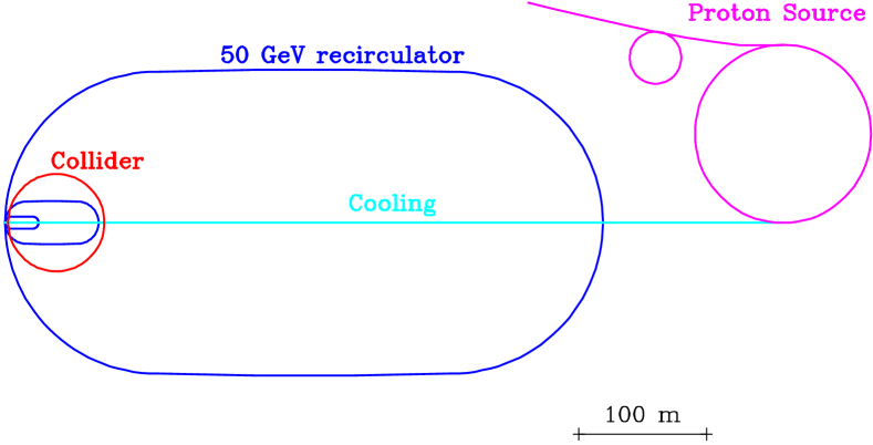
5.2 Longitudinal Cooling
Currently there is no satisfactory solution for emittance exchange and this remains a major stumbling block towards realizing a muon collider. Figure 5.4 shows one of the schemes that are under consideration to solve the emittance exchange problem.
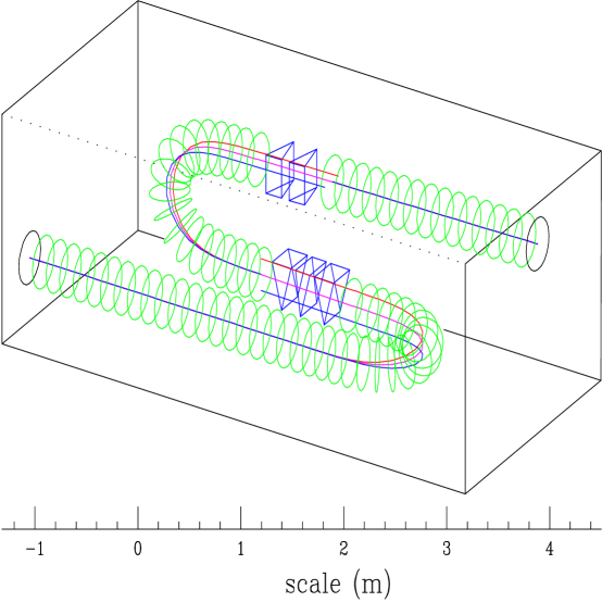
Ring Coolers have been introduced by Balbekov [107]. Figure 5.5 shows a ring design currently under study. The advantage of ring coolers is that one can circulate the muons in a cooling ring of circumference 30 m and circulate the muons many turns, thereby reusing the cooling channel elements. It can be shown that such devices can cool in 6-D space. Figure 5.6 shows a simulation of the ring cooler that demonstrates cooling in 6 dimensions. It should be emphasized that this simulation uses idealized magnetic fields. A study is currently under way to see if these results hold up with realistic magnetic fields.
Ring coolers hold the promise to solve the emittance exchange problem. However, it has yet to be demonstrated that it is possible to inject into and extract from them high emittance beams. If these problems can be solved, it may be possible to cascade a number of ring coolers each providing cooling by a factor 30 to achieve the needed factor of 106. Another ring cooling design by Al Garren [104] operates at higher energies and also holds the promise of 6-D cooling.
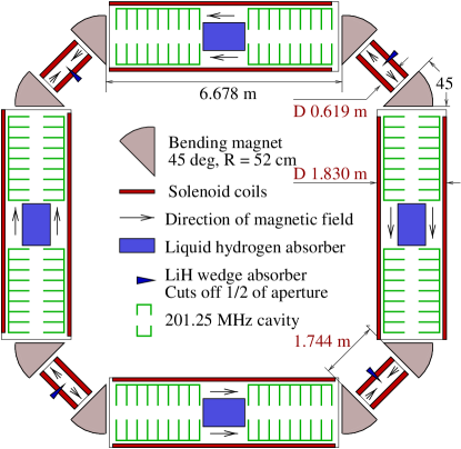
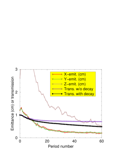
If one can solve the longitudinal cooling problem, both neutrino factories and muon colliders will benefit.
5.3 Higher Energy Muon colliders
Once the cooling problems have been solved to realize the first muon collider, acceleration to higher energies becomes possible. Colliders with 4 TeV center of mass energy have been studied [15] and Table 5.2 lists the parameters for such a collider. The radiation from the neutrinos from the muon decay begins to become a problem at CoM energies of 3 TeV. One may attempt to solve this by a number of means, including optical stochastic cooling of muons in the collider, whereby one can get the same luminosity with less intensity.
| Linac | RLA1 | RLA2 | RCS1 | RCS2 | |
|---|---|---|---|---|---|
| E (GeV) | 0.1 1.5 | 1.5 10 | 10 70 | 70 250 | 250 2000 |
| frf (MHz) | 30 100 | 200 | 400 | 800 | 1300 |
| Nturns | 1 | 9 | 11 | 33 | 45 |
| Vrf(GV/turn) | 1.5 | 1.0 | 6 | 6.5 | 42 |
| Cturn(km) | 0.3 | 0.16 | 1.1 | 2.0 | 11.5 |
| Beam time (ms) | 0.0013 | 0.005 | 0.04 | 0.22 | 1.73 |
| (cm) | 50 8 | 4 1.7 | 1.7 0.5 | 0.5 0.25 | 0.25 0.12 |
| (GeV) | 0.005 0.033 | 0.067 0.16 | 0.16 0.58 | 0.58 1.14 | 1.14 2.3 |
| Loss (%) | 5 | 7 | 6 | 7 | 10 |
5.4 Muon Collider Detectors
Figure 5.7 shows a strawman muon collider detector for a Higgs factory simulated in Geant. The background from muon decay sources has been extensively studied [15]. At the Higgs factory, the main sources of background are from photons generated by the showering of muon decay electrons. At the higher energy colliders, Bethe-Heitler muons produced in electron showers become a problem. Work was done to optimize the shielding by using specially shaped tungsten cones [15]. The background rates obtained were shown to be similar to those predicted for the LHC experiments. It still needs to be established whether pattern recognition is possible in the presence of these backgrounds.
Chapter 6 Costs and Staging Options
6.1 Costs
6.1.1 Methodology
We have specified each system of the Study-II Neutrino Factory in sufficient detail to obtain a “top-down” cost estimate for it. Clearly this estimate is not the complete and detailed cost estimate that would come from preparing a full Conceptual Design Report (CDR). However, there is considerable experience in designing and building accelerators with similar components, so we have a substantial knowledge base from which costs can be derived. The costs summarized here were obtained mainly in that way.
Where available, we have used costs from existing components—scaled as needed to reflect essential changes—to represent the expected costs to fabricate what we need. This applies to the Proton Driver, the superconducting and normal conducting magnets and their power supplies, the rf cavities, and conventional facilities and utilities. In some cases, we were able to take advantage of experience in designing similar components in a different context. For example, the target facility we require closely resembles that needed for the Spallation Neutron Source (SNS) project at ORNL, for which detailed CDR-level designs already exist and construction is under way. The superconducting target solenoid is not a standard device, but there is a magnet of similar size and field strength, designed for the ITER project, that serves as a convenient scaling model. In the case of rf power sources, we made use of the multi-beam klystron (MBK) example developed at DESY for TESLA, along with expertise in developing other high-power tubes at U.S. Laboratories. For devices such as the MBK, which are a significant extrapolation from existing hardware, allowance was made for a substantial development program, whose cost was amortized over the initial complement of devices needed for the Neutrino Factory.
6.1.2 Facility Costs
The Neutrino Factory design we describe here favors feasibility over cost reduction. Thus, we do not claim to present a fully cost-optimized design, nor one that has been reviewed from the standpoint of “value engineering.” In that sense, there is hope that a detailed design study will reduce the costs compared with what we estimate here. We have put in an allowance of 10% for each of the systems to account for things we have not considered in detail at this stage. Only direct costs are included here, that is, the estimates do not contain allowances for EDIA, laboratory overhead burdens, or contingency. The breakdown by system is summarized in Table 6.1; these costs are given in FY01 dollars. However, to facilitate comparison with the Feasibility Study-I estimate, in the last column of Table 6.1 we converted our costs to FY00 dollars, using the DOE-approved inflation factor of 2.5%.
It is interesting to compare our estimate with that of Study-I; in this study, we have improved the performance by a factor of six over that reached in Study-I, at a total cost (estimated in the same way for both designs) of about 3/4 of that in the original study. This is an encouraging trend and, as noted, we have some hope that it will continue.
| System | Sum | Othersa | Total | Reconciliationb |
|---|---|---|---|---|
| ($M) | ($M) | ($M) | (FY00 $M) | |
| Proton Driver | 168.0 | 16.8 | 184.8 | 180.0 |
| Target Systems | 92.0 | 9.2 | 101.2 | 98.0 |
| Decay Channel | 4.6 | 0.5 | 5.1 | 5.0 |
| Induction Linacs | 319.0 | 31.9 | 350.9 | 343.0 |
| Bunching | 69.0 | 6.9 | 75.9 | 74.0 |
| Cooling Channel | 317.0 | 31.7 | 348.7 | 340.0 |
| Pre-accel. linac | 189.0 | 18.9 | 207.9 | 203.0 |
| RLA | 355.0 | 35.5 | 390.5 | 381.0 |
| Storage Ring | 107.0 | 10.7 | 117.7 | 115.0 |
| Site Utilities | 127.0 | 12.7 | 139.7 | 136.0 |
| Totals | 1,747 | 175 | 1,922 | 1,875 |
| aOthers is 10% of each system to account for missing items, | ||||
| as was used in Study-I. | ||||
| bReconciliation represents the Study-II costs given in FY00 | ||||
| dollars to permit direct comparison with Study-I costs. | ||||
| The inflation factor used (1/1.025) is per DOE official rates. | ||||
6.2 Staging Options
During the HEPAP sub-panel presentations on Neutrino Factory R&D that took place at BNL on April 19, 2001, the MC was asked to discuss the time scale for arriving at a Muon Collider, and to outline possible staging options that would lead to a high-performance Neutrino Factory and, at a later date, a Muon Collider. The discussion below supplements our response to these questions.
The collaboration has now completed two detailed “Feasibility Studies” of Neutrino Factories. These studies included end-to-end simulations of the non-conventional parts of the facilities, and sufficient engineering studies to form the basis for defensible R&D plans. The schedule presented indicated that, with adequate R&D support, construction of a Neutrino Factory could begin in 2007. Depending upon available resources, this could be either a complete high-performance Neutrino Factory capable of searching for CP violation in the lepton sector, or a more modest first step that would address many outstanding neutrino oscillation questions, and would be upgradeable in a staged manner to a high-performance facility.
Expanding on the staging possibilities that could be considered as we proceed toward a Neutrino Factory, we note that there are a number of options:
-
1.
A high-intensity Proton Driver that could be used to provide an upgraded conventional neutrino “superbeam” and also to support a new round of kaon experiments if desired. We believe construction of the Proton Driver, based on either the BNL AGS or the FNAL proton source, could begin in 2–3 years and be completed within 4–5 years from today.
-
2.
A very high intensity, low energy, muon source making about 1021 muons per year available for stopped muon experiments. This might enable e conversion, for example, to be probed with a sensitivity exceeding that of the MECO experiment by several orders of magnitude, and could also support a broad physics community beyond high-energy physics. We believe construction of the muon facility could begin 7–8 years from now, or even sooner (in parallel with construction of the proton source) if it were deemed to have sufficiently high priority.
In addition to the MC work on a Neutrino Factory, we are committed to developing the technology required for a Muon Collider. Indeed, it was our interest in Muon Colliders that led us initially to study the production of intense muon beams. By focusing on the easier problem of the Neutrino Factory, we have made more rapid progress and, at the same time, established many of the technologies needed for the Collider. However, this approach has resulted in a considerable difference in our level of understanding of the two types of facility.
Unlike the situation for the Neutrino Factory, we do not yet have a complete scenario, with parameters and chosen technologies, for the Collider. As a result, we have no end-to-end simulations, little engineering, and no cost estimates. Many of the required components are natural extensions of those used in a Neutrino Factory, but some are specific to the Collider (e.g., emittance exchange and the Collider ring itself), and many involve large extrapolations from the Neutrino Factory parameter regime (e.g., the total amount of cooling, the final beam emittance, the charge per bunch). There are ideas of how a Collider scenario might look, and there has been substantial progress on possible technologies for some of these components (e.g., a ring cooler that would give emittance exchange, and lithium lens cooling to the required very small final emittance). However, these studies are far from complete. Thus, we are not yet in a position to conduct the “feasibility” study that would be needed to make a complete R&D plan for this new and exciting machine.
Before we can reach the feasibility study stage, we must establish robust technical solutions to emittance exchange, issues related to the high bunch charges, techniques for cooling to the required final emittances, and the design of a very low * collider ring. We are confident that solutions exist along the lines we have been investigating, but at present we do not have enough R&D support to adequately pursue both the Collider studies and the Neutrino Factory design studies. Unless and until we obtain such support, it is hard to predict how long it will take to solve the emittance exchange and other collider-specific problems—it could be very soon, or it could be a much longer time.
In view of the above, it should be clear that any estimated time scale quoted for a Muon Collider has considerable uncertainty. The MC has previously presented one time scale, based on particular assumptions that the R&D for the Collider would mainly follow that for the Neutrino Factory. Clearly, with more optimistic assumptions a significantly faster time scale might be possible. We have gone through the exercise of considering such schedules, and they have the potential to reduce the time to start physics at a Muon Collider by many years. On the other hand, it is also possible—given the conceptual and technical uncertainties and the current limits on funding—that the real time scale will be longer.
We in the MC are eager to advance to the stage of building a Muon Collider on the earliest possible time scale. However, for that to happen there is an urgent need to greatly increase support for our R&D so that we can address the vital issues.
As discussed above, it seems quite possible—perhaps even likely—that the Neutrino Factory would be built in stages, both for programmatic and for cost reasons. In what follows we outline a possible staging concept that provides good physics opportunities with reasonable cost increments. The staging scenario we consider here is not unique, nor is it necessarily optimized. Discussions at Snowmass will serve to sharpen the thoughts of the physics community on what is an optimal staging scenario. Depending on the results of our technical studies and the results of continued searches for the Higgs boson, it is hoped that the Neutrino Factory is really the penultimate stage, to be followed later by a Muon Collider (Higgs Factory). We assume this scenario in the staging discussion that follows.
Because the physics program would be different at different stages, it is impractical at this time to consider detector costs. Therefore, none of the costs listed in Section 6.2 include any detector costs. To better represent the incremental costs of a staged approach, utility costs, which are called out separately in Table 6.1, have been apportioned among the various stages.
6.2.1 Stage 1
In the first stage, we envision a Proton Driver and a Target Facility to create superbeams. The Driver could begin with a 1 MW beam level (Stage 1) or could be designed from the outset to reach 4 MW (Stage 1a). (Since the cost differential between 1 and 4 MW is not large, we do not consider any intermediate options here.) Because the Proton Driver design is site specific, cost estimates are slightly different for the BNL and FNAL options. The Target Facility cost we take from Study-II (see Table 6.1). It is assumed, as was the case for both Study-I and Study-II, that the Target Facility is built from the outset to accommodate a 4 MW beam. Based on the Study-II results, a 1 MW beam would provide about /s ( /year) and a 4 MW beam about /s ( /year) into a solenoid channel.
Costs for Stage 1 are summarized in Table 6.2. If a horn were used in place of the Study-II solenoid capture system, the intensities may decrease but the potential cost savings might be in the range of $30–40M. This option has not been explored in our Studies to date, and we have not yet assessed the feasibility of using a horn for the 4 MW scenario. As noted earlier, the costs in Table 6.2 are only facility costs and do not include detectors.
In addition to the neutrino program, this stage will also benefit , , and programs, as discussed in [105, 106]
| BNL option | FNAL 16-GeV option | FNAL 8-GeV option | |
|---|---|---|---|
| ($M) | ($M) | ($M) | |
| 1 MW | 310 | 330 | 250 |
| 4 MW | 400 | 410 | 330 |
6.2.2 Stage 2
In Stage 2, we envision a muon beam that has been phase rotated (to give a reasonably low momentum spread) and transversely cooled. In the notation of Study-II, this stage takes us to the end of the cooling channel. Thus, we have access to a muon beam with a central momentum of about 200 MeV/, a transverse (normalized) emittance of 2.7 mm-rad and an rms energy spread of about 4.5%. The intensity of the beam would be about /s ( /year) at 1 MW, or /s ( /year) at 4 MW. The incremental cost of this option is $840M, based on assuming the cooling channel length adopted in Study-II. If more intensity were needed, and if less cooling could be tolerated, the length of the cooling channel could be reduced. As an example, stopping at the end of Lattice 1 instead of the end of Lattice 2 would decrease the incremental cost by about $180M, with the penalty of roughly doubling the transverse emittance.
6.2.3 Stage 3
In Stage 3, we envision using the Pre-acceleration Linac to raise the beam energy to roughly 2.5 GeV. The incremental cost of this option is about $220M. At this juncture, it may be appropriate to consider a small storage ring, comparable to the ring at BNL, to be used for the next round of muon experiments. This ring would, in some sense, be a throw-away device. No cost estimate has been made for this ring, but it would be expected to cost a few tens of millions. For the present purpose, we take the cost of such a ring, which we refer to as Stage 3a, as $30M.
6.2.4 Stage 4
At Stage 4, we envision having a complete Neutrino Factory operating with a 20 GeV storage ring. The incremental cost of this stage, which includes the RLA and the storage ring, is $550M. If it were necessary to provide a 50 GeV muon beam as Stage 4a, an additional RLA and a larger storage ring would be needed. The incremental cost to go from Stage 4 to Stage 4a would be an additional $700–800M.
Table 6.3 summarizes the incremental costs for each stage of a Neutrino Factory, exclusive of detector costs.
| Stage | Incremental Cost |
|---|---|
| ($M) | |
| 1 (1 MW Proton Driver) | 250–330 |
| 1a (4 MW Proton Driver) | 80 |
| 2 (Cooled muons, 200 MeV/) | 660–840 |
| 3 (2.5 GeV muons) | 220 |
| 3a ( storage ring) | 30 |
| 4 (20-GeV Neutrino Factory) | 550 |
| 4a (50-GeV Neutrino Factory) | 700–800 |
6.2.5 Stage 5
In Stage 5, we can envision an entry level Muon Collider to operate as a Higgs Factory. No cost estimate has yet been prepared for this stage, so we mention here only the obvious “cost drivers.” First, the initial muon beam must be prepared as a single bunch of each charge. This may involve an additional ring for the proton driver to coalesce proton bunches into a single pulse. The cooling will have to be significantly augmented. First, a much lower transverse emittance is needed, and second, it will be necessary to provide emittance exchange to maintain a reasonable transmission of the muons. The additional cooling will permit going to smaller solenoids and higher frequency rf systems (402.5 or perhaps 805 MHz), which should lower the incremental cost somewhat. Next, we will need considerably more acceleration, though with smaller energy acceptance and aperture requirements than at present. Lastly, we will need a very low lattice for the storage ring, along with mitigation of the potentially copious background levels near the interaction point. In this case the detector is, in effect, part of the Collider and cannot be ignored in terms of its cost impact.
Of the items mentioned, it is likely that the additional cooling and the additional acceleration are the most significant cost drivers. Future work will define the system requirements better and permit a cost estimate of the same type provided for Studies-I and -II.
Chapter 7 R&D Program
7.1 Introduction
Successful construction of a muon storage ring to provide a copious source of neutrinos requires many novel approaches to be developed and demonstrated. To construct a high-luminosity Muon Collider is an even greater extrapolation of the present state of accelerator design. The breadth of R&D issues to be dealt with is beyond the resources available at any single national laboratory or university.
For this reason, in 1995, interested members of the high-energy physics and accelerator physics communities formed the Neutrino Factory and Muon Collider Collaboration (MC) to coordinate the required R&D efforts nationally. The MC comprises three sponsoring national laboratories (BNL, FNAL, LBNL) along with groups from other U.S. national laboratories and universities and individual members from non-U.S. institutions. Its task is to define and carry out R&D required to assess the technical feasibility of constructing initially a muon storage ring that will provide intense neutrino beams aimed at detectors located many thousands of kilometers from the accelerator site, and ultimately a collider that will carry out fundamental experiments at the energy frontier in high-energy physics. The MC also serves to coordinate muon-related R&D activities of the NSF-sponsored University Consortium (UC) and the state-sponsored Illinois Consortium for Accelerator Research (ICAR), and is the focal point for defining the needs of muon-related R&D to the managements of the sponsoring national laboratories and to the funding agencies (both DOE and NSF). Though the MC was formed initially to carry out R&D that might lead eventually to the construction of a Muon Collider, more recently its focus has shifted mainly, but not exclusively, to a Neutrino Factory.
The MC maintains close contact with parallel efforts under way in Europe (centered at CERN) and in Japan (centered at KEK). Through its international members, the MC also fosters coordination of the international muon-beam R&D effort. Two major initiatives, a Targetry Experiment (E951) in operation at BNL and a Muon Cooling R&D program (MUCOOL), have been launched by the MC. In addition, the Collaboration, working in conjunction with the UC and ICAR in some areas, coordinates substantial efforts in accelerator physics and component R&D to define and assess parameters for feasible designs of muon-beam facilities.
7.2 R&D Goals
The approach taken by the MC to define the overall R&D program was to decide what we wished to accomplish in a five-year time span in each area and then determine what is needed to reach that goal. For this exercise, we assume a technology-limited schedule, that is, we assume that the required financial resources and personnel are available. With this approach, we expect that a five-year technology-limited plan will result in:
-
•
all optics designs being completed and self-consistent
-
•
validation experiments being completed or well along
-
•
all required hardware being defined
-
•
prototypes of the most challenging and costly components being completed or well along, i.e., we know how to build the “hard parts”
-
•
being ready to begin the design of, and provide cost estimates for, most of the remaining components
At the end of the five-year period, the above goals would put the MC in position to request permission to begin a formal Conceptual Design Report (CDR) for a Neutrino Factory. It is expected that this CDR stage would take 1–2 years to complete. The CDR would document a complete and fully engineered design for the facility, including a detailed bottom-up cost estimate for all components. This document would form the basis for a full technical, cost, and schedule review of the construction proposal, subsequent to which construction could commence after obtaining government approval.
As an “intermediate milestone” we envision preparing a Zeroth-order Design Report (ZDR) after three years. The ZDR will examine the complete systems of a Neutrino Factory, making sure that nothing is forgotten, and will show how the parts merge into a coherent whole. While it will not present a fully engineered design with a detailed cost estimate, enough detail will be presented to ensure that the critical items are technically feasible and that the proposed facility could be successfully constructed and operated at its design specifications.
7.3 R&D Program Issues
A Neutrino Factory comprises the following major systems: Proton Driver, Target and (Pion) Capture Section, (Pion-to-Muon) Decay and Phase Rotation Section, Bunching and Matching Section, Cooling Section, Acceleration Section, and Storage Ring. These same categories exist for a Muon Collider, with the exception that the Storage Ring is replaced by a Collider Ring having a low-beta interaction point and a local detector. Parameters and requirements for these systems are generally more severe in the case of the Muon Collider, so a Neutrino Factory can properly be viewed as a scientifically productive first step toward the eventual goal of a collider. As noted earlier, the R&D program we envision is designed to answer the key questions needed to embark upon a ZDR after three years. After completion of the full five-year program, it is expected that a formal Conceptual Design Report could begin. Longer-term activities, related primarily to the Muon Collider, are also supported and encouraged.
Each of the major systems has significant issues that must be addressed by R&D activities, including a mix of theoretical, simulation, modeling, and experimental studies, as appropriate. A brief summary of the key physics and technology issues for each major system is given below.
Proton Driver
-
•
Production of intense, short proton bunches, e.g., with space-charge compensation and/or high-gradient, low frequency rf systems
Target and Capture Section
-
•
Optimization of target material (low-Z or high-Z) and form (solid, moving band, liquid-metal jet)
-
•
Design and performance of a high-field solenoid (20 T) in a very high radiation environment
Decay and Phase Rotation Section
-
•
Development of high-gradient induction linac modules having an internal superconducting solenoid channel
Bunching and Matching Section
-
•
Design of efficient bunching system
Cooling Section
-
•
Development and testing of high-gradient normal conducting rf (NCRF) cavities at a frequency near 200 MHz
-
•
Development and testing of efficient high-power rf sources at a frequency near 200 MHz
-
•
Development and testing of LH2 absorbers for muon cooling
-
•
Development and testing of candidate diagnostics to measure emittance and optimize cooling channel performance
-
•
Design of beamline and test setup (e.g., diagnostics) needed for demonstration of transverse emittance cooling
-
•
Development of six-dimensional analytical theory to guide the design of the cooling section
Acceleration Section
-
•
Optimization of acceleration techniques to increase the energy of a muon beam (with a large momentum spread) from a few GeV to a few tens of GeV (e.g., recirculating linacs, rapid cycling synchrotrons, FFAG rings) for a Neutrino Factory, or even higher for a Muon Collider
-
•
Development of high-gradient superconducting rf (SCRF) cavities at frequencies near 200 MHz, along with efficient power sources (about 10 MW peak) to drive them
-
•
Design and testing of components (rf cavities, magnets, diagnostics) that will operate in the muon-decay radiation environment
Storage Ring
-
•
Design of large-aperture, well-shielded superconducting magnets that will operate in the muon-decay radiation environment
Collider
-
•
Cooling of 6D emittance (x, px, y, py, t, E) by up to a factor of
-
•
Design of a collider ring with very low beta (a few mm) at the interaction point having sufficient dynamic aperture to maintain luminosity for about 500 turns
-
•
Study of muon beam dynamics at large longitudinal space-charge parameter and at high beam-beam tune shifts
Detector
-
•
Simulation studies to define acceptable approaches for both near and far detectors at a Neutrino Factory and for a collider detector operating in a high-background environment
-
•
Develop ability to measure the sign of electrons in the Neutrino Factory detectors
7.4 FY 2001 R&D Plans
7.4.1 Targetry
This year, a primary effort of the Targetry experiment E951 was to carry out initial beam tests of both a solid carbon target and a mercury target. Both of these goals were accomplished at a beam intensity of about 4 1012 ppp, with encouraging results. Measurements of the velocity of droplets emanating from the jet as it is hit with the proton beam pulse from the AGS compare favorably with simulation estimates. High-speed photographs indicate that the beam disruption at the present intensity does not appear to propagate back upstream toward the jet nozzle, which will ease mechanical design issues for this component.
7.4.2 MUCOOL
The primary efforts this year were to complete the Lab G rf test area and begin high-power tests of the 805 MHz cavities that were completed earlier this year. A test solenoid for the facility, capable of operating either in solenoid mode (its two independent coils powered in the same polarity) or gradient mode (with the two coils opposed), was tested up to its design field of 5 T. An open-cell cavity has been installed and conditioning at high-power is under way to explore gradient limitations we will face in a cooling channel. A second cavity, having Be foils to close the beam iris, is now being tuned to final frequency. This cavity will permit an assessment of the behavior of the foils under rf heating and give indications about multipactor effects.
Development of a prototype LH2 absorber is in progress. A large diameter, thin (125 m) aluminum window has been successfully fabricated by machining from a solid disk. A new area is being developed at FNAL for testing the absorbers. This area, located at the end of the proton linac, will be designed to permit beam tests of components and detectors with 400 MeV protons. It will also have access to 201-MHz high-power rf amplifiers for cavity testing.
Initial plans for a cooling demonstration will be firmed up this year. This topic will be covered separately in Section 7.10.
7.4.3 Feasibility Study-II
This year the MC participated heavily in a second Feasibility Study for a Neutrino Factory, sponsored by BNL. The results of the study were quite encouraging (see Chapter 4 of this report), indicating that a neutrino intensity of per Snowmass year can be sent to a detector located 3000 km from the muon storage ring. It was clearly demonstrated by means of these two studies that a Neutrino Factory could be sited at either FNAL or BNL. Component R&D needed for such a facility was identified, and is included in the program outlined here.
7.4.4 Simulation and Theory
In addition to Study-II, this year the effort has focused on longitudinal dynamics. We are developing theoretical tools for managing the longitudinal aspects of cooling, with the goal of developing approaches to 6D cooling, i.e., “emittance exchange.” This is a crucial aspect for the eventual development of a Muon Collider, and would benefit a Neutrino Factory as well. In particular, work has begun on studies of the ring cooler [107] which has the potential to cool in 6D space, if the beam can be injected and extracted from it. Avenues are being explored to see if it can also function as a cooling demonstration where pions are produced in an internal target.
7.4.5 Component Development
The main effort in this area is aimed at development of a high-gradient 201-MHz SCRF cavity. This year a test area of suitable dimensions is being fabricated at Cornell. In addition, a prototype cavity is being fabricated for the Cornell group by our CERN colleagues. Mechanical engineering studies of microphonics and Lorentz detuning issues are being carried out. These will lead to plans to stiffen the cavity sufficiently to avoid serious vibration problems in these large structures.
7.4.6 Collider R&D
Studies of possible hardware configurations to perform emittance exchange, such as the compact ring proposed by Balbekov [107], are now getting under way. An emittance exchange workshop was held at BNL in the fall of 2000, and a second workshop is being planned for October, 2001. In addition to the efforts on emittance exchange, a workshop on an entry-level Muon Collier to serve as a Higgs Factory was hosted this year by UCLA and Indiana University. The focus of this meeting was to begin exploring the path to get from a Neutrino Factory to a Higgs Factory. Even beyond the cooling issues, the bunch structure required for the two facilities is very different (the Collider demands only a single bunch), so the migration path is not straightforward.
7.5 FY2002 R&D plans
7.5.1 Targetry
For the targetry experiment, design of a pulsed 20-T solenoid and its 5-MW power supply will begin. One or more selected targets will be tested with beam this year. Simulations in support of this activity will continue. Improvements in the AGS extraction system will be investigated, with the goal of approaching the design single-bunch intensity of 1.7 1013 ppp on target. An upgrade of the AGS extraction kicker to permit fast extraction of the entire beam will be studied.
Radiation tests on selected coil materials will begin this year, to verify behavior prior to actual magnet fabrication. As part of this work, we will measure neutron yields from the target, to compare with predictions of the MARS code. Systems studies of the target facility will continue to identify and test key issues related to handling and remote maintenance, with special attention paid to mercury-handling issues.
The next level of engineering concepts for a band target will be developed. If its engineering aspects can be mastered, this approach might be a good technical backup to the mercury jet .
7.5.2 MUCOOL
Testing work remaining for the 805 MHz components will continue this year in Lab G. Completion of the linac test area at FNAL, initially to accommodate the absorber tests and ultimately to house the 201-MHz cavity test, will occur this year. Thermal tests of a prototype absorber will commence there. Design and fabrication of cooling channel components required for the initial phase of testing will begin, including a high-power 201 MHz NCRF cavity and diagnostics that could be used for the experiment. Provisions will be made to test both Be windows and grids for the cavity.
7.5.3 Simulations and Theory
Simulations this year will focus on iterating the front-end channel design to be compatible with realizable component specifications. Studies of the acceleration system and the storage ring will include errors and fringe-field effects. From these studies will come component specifications for the acceleration system and storage ring components. Simulation efforts in support of a cooling demonstration program, and work on emittance exchange, will both continue.
7.5.4 Component Development
A prototype induction linac cell, designed to operate at 1.5 MV/m and including an internal superconducting solenoid with suitable dimensions and field strength, will be designed. A prototype 201-MHz SCRF cavity will be tested at low power. An initial input power coupler design will be tested and validated. Detuning issues associated with the pulsed rf system will also be evaluated. Finally, because of the large stored energy in a 201 MHz SCRF cavity, a reliable quench protection system must be designed and tested. Design of a prototype high-power rf source will begin, in collaboration with industry.
7.6 FY2003 R&D plans
7.6.1 Targetry
For the targetry experiment, AGS extraction kicker modifications to permit high intensity beam tests (1 1014 protons per pulse) will begin. The 20-T target solenoid for E951 will be fabricated this year. Measurements of particle yield in this target geometry, but without a solenoid will be made. These will use a much lower beam intensity (1 106 protons per pulse), for 6 weeks of parasitic beam time. Tests of radiation-hard materials will be completed and selected candidate materials will be used to begin manufacture of an actual (warm) solenoid coil for testing in a high-radiation environment. The target simulation effort this year will focus on understanding experimental results from the targetry experiment.
7.6.2 MUCOOL
High-power tests of the 201-MHz NCRF cavity will begin in the linac test area. Beam tests will be carried out with a prototype LH2 absorber. Fabrication of all remaining components, such as the solenoids, will commence.
7.6.3 Simulations and Theory
Additional effort will be given to beam dynamics studies in the RLAs and storage ring, including realistic errors. Work on finalizing the optics design for the arcs will be done. Assessment of field-error effects on the beam transport will be made to define acceptance criteria for the magnets. This will require use of sophisticated tracking codes like COSY that permit rigorous treatment of field errors and fringe-field effects. Because the beam circulates in each RLA for only a few turns, the sensitivity to magnet errors should not be extreme, though the large energy spread will tend to enhance it. In many ways, the storage ring is one of the most straightforward portions of a Neutrino Factory complex. However, beam dynamics is an issue here as the muon beam must circulate for many hundreds of turns. Use of a tracking code such as COSY is required to assess fringe field and large aperture effects. As with the RLAs, the relatively large emittance and large energy spread enhance the sensitivity to magnetic field and magnet placement errors. Suitable magnet designs are needed, with the main technical issue being the relatively high radiation environment. Another lattice issue that must be studied is polarization measurement. In the initial implementation of a Neutrino Factory it is expected that polarization will not be considered, but its residual value may be important in analyzing the experiment.
7.6.4 Component Development
Magnet designs suitable for the arcs of the recirculating linacs (RLAs) and the muon storage ring will be examined this year. Both conventional and superconducting designs will be compared where either is possible. With SC magnets, radiation heating becomes an issue and must be assessed and dealt with. Designs for the splitter and recombiner magnets will be developed and—depending on how nonstandard they are—prototypes will be built. Tests of a 201 MHz SCRF cavity will continue this year, including demonstration of the ability to shield nearby magnetic fields in a realistic lattice configuration. Fabrication of a prototype induction linac module and its pulser system will begin this year.
7.7 FY2004 R&D plans
7.7.1 Targetry
For the targetry experiment, the work this year will focus on completing systems studies of the final target station, including issues of radiation handling and safety. Target facility studies will progress to prototypes or full-size models of key components, as needed, to verify the design concepts. A (normal conducting) test solenoid coil based on the materials tests in prior years will be completed and tested in a radiation environment.
7.7.2 MUCOOL
A full cooling cell will be assembled and bench tested. After testing, it is anticipated that these components will be installed in a beam line and tested with protons. The goal here is not to demonstrate cooling, but to demonstrate operation of the components in a radiation environment. Upon completion of the integration tests, these components will be available for testing in a muon beam as part of the cooling demonstration experiment.
7.7.3 Theory and Simulation
Work on the Zeroth-order Design Report will commence this year. This activity will require about two years of significant effort, leading to a document that presents a description of all aspects of a Neutrino Factory, in sufficient detail to demonstrate technical feasibility of the full facility.
7.7.4 Component Development
High-power tests of the 201-MHz SCRF cavity will be carried out at FNAL. The induction linac prototype module will be completed and tests will begin.
7.8 FY 2005 R&D plans
This year should see the completion of the ZDR followed by a community review of its contents. Thereafter, we will be ready to seek permission to begin a formal CDR. Work on the Cooling Demonstration Experiment (see Section 7.10) will be a primary activity this year.
7.9 Required Budget
Table 7.1 summarizes the projected budget requirements for the activities described above. The numbers represent our estimate of the required resources from all sources, including direct DOE funding for the MC, DOE base program support from the sponsoring Laboratories, NSF support to the UC, state support for the ICAR, and possible contributions by foreign collaborators. The scale of R&D is consistent with the experience of other large accelerator projects, both past and present, and in that sense is “realistic.” The funding profile in Table 7.1 corresponds to the technology-limited schedule we are considering. If this level of funds is not available, the R&D work would proceed more slowly. Indeed, the amount of support available in FY2001, and that projected for FY2002, already fall short of what is required, with the result that the schedule shown here has begun to slip. It is worth noting that the increase in FY2004 and FY2005 is associated mainly with the cooling demonstration experiment. If we were to assume equal sharing among the U.S., Europe, and Japan in this endeavor, as seems reasonable, then about $8M of the tabulated costs in each of these years would be borne by non-U.S. funds. In that case, a program with roughly flat funding (from all U.S. sources) in the $15M range would permit us to complete the R&D program in a timely way.
| R&D area | FY01 | FY02 | FY03 | FY04 | FY05 | Sum |
|---|---|---|---|---|---|---|
| ($M) | ($M) | ($M) | ($M) | ($M) | ($M) | |
| MUCOOL | 4.9 | 3.8 | 4.3 | 11.3 | 11.2 | 35.4 |
| Targetry | 4.7 | 3.8 | 4.1 | 3.5 | 2.1 | 18.2 |
| Beam Simul. | 2.3 | 2.0 | 2.0 | 2.0 | 2.0 | 10.3 |
| Accel./SR | 1.0 | 0.7 | 0.7 | 0.7 | 0.7 | 3.6 |
| Components | 1.9 | 4.5 | 7.5 | 4.3 | 4.0 | 22.2 |
| ZDR Prep. | 4.0 | 6.0 | 10.0 | |||
| TOTAL | 15 | 15 | 19 | 26 | 26 | 100 |
7.10 Cooling Demonstration Experiment
One of the more important R&D tasks that is needed to validate the design of a Neutrino Factory is to measure the cooling effects of the hardware we propose. At the recent NUFACT’01 Workshop in Japan, a volunteer organization, to be chaired initially by Alain Blondel from Geneva University, was created to organize a cooling demonstration experiment that would begin in 2004. See Chapter on International activities on further details on this committee. Present membership in this group (with representatives from the U.S., Europe, and Japan), the “Muon Cooling Demonstration Experiment Steering Committee” (MCDESC), is listed in the chapter on International Activities. The Steering Committee is responsible for choosing a technical team to develop the proposal details, suggest a beamline, and propose components to be tested, including absorbers, rf cavities and power supplies, magnets, and diagnostics. This technical team will likewise be assembled from experts from the three geographical regions.
The aim of the proposed experiment is twofold:
-
1.
To show that we can design, engineer, and build a section of cooling channel capable of giving the desired performance for a Neutrino Factory
-
2.
To place it in a muon beam and measure its performance, i.e., to validate that it performs as predicted by simulations
It is clear that the experience gained from this experiment will be invaluable for the design of an actual cooling channel.
The present concept is to carry out a single-particle measurement of cooling effects, starting from a single cell of cooling hardware. We believe that the measurement of the emittance change can be done with a precision of about 0.5% with standard single-particle detection techniques. The main technical uncertainty in this concept is the ability of the detection equipment to function properly in the large x-ray flux resulting from very high gradient rf cavity operation. This aspect can be explored almost immediately in the Lab G test area at FNAL, where high-gradient cavity testing is just getting under way. (The x-ray intensity from the cavity is expected to scale with electric field as . Taking a positive slant, this means that a small reduction in operating voltage will lead to a large reduction in x-ray intensity.)
The plan of the Steering Committee is to create a short document (10 pages) by December 15, 2001 that will define the key technology choices and the venue for the experiment. Thereafter, a full technical proposal, including a cost estimate suitable for presentation to the various funding agencies, would be prepared by June, 2002. Though there obviously is no cost estimate yet, it is expected that getting a single cooling cell into a muon beam will require about $10M. Thereafter, it is expected that more cells would be added, either identical to that in the first test or perhaps of a different design. With this in mind, it is reasonable to suppose that the initial funding commitment needed—shared among the three regions—will be about $20M. This is consistent with the estimate presented in Table 7.1. However, the profile in Table 7.1 would have to move forward by one year. The overall U.S. requirement of $15M per year would remain unchanged. (Later, it may be of interest to continue this experimental effort, perhaps including longitudinal cooling techniques, though that is certainly beyond the initial scope of the proposed experiment.)
Chapter 8 International Activities
In Europe there exists an accelerator study group mandated by CERN and a physics study group mandated by the European committee for Future Accelerators (ECFA) [108]. These activities are co-ordinated by European Muon Steering Committee (MUG) whose membership [109] is: Alain Blondel (chair), Friedrich Dydak, John Ellis, Enrique Fernandez, Helmut Haseroth, Vittorio Palladino, Ken Peach, Michel Spiro, Paolo Strolin.
The primary center of work is at CERN. The work of the accelerator group was described at NuFact01 by R. Garoby [110]. The general approach to a Neutrino Factory, the design of which is co-authored by more than 90 physicists, is based upon a 2.2 GeV proton linac [111]. They have a good number of R&D activities. These include a large theoretical / modeling group, work on detectors (including many universities in Europe), involvement in the scattering experiment (MUSCAT) at Triumf (involving CLRC, Birmingham, and Imperial College and CERN), and participation in target work at Brookhaven, engaging in target work at CERN, RAL and Grenoble, work on low frequency RF cavities, a major production experiment at the PS (HARP), and involvement in the International Muon Cooling Experimental Demonstration.
Activities in Japan were described by S. Machida at NuFact01 [110]. Their general approach is a series of FFAG accelerators. No manipulation of longitudinal phase space and no cooling of transverse phase space is needed in their approach. Their R&D program is not very extensive, but they are cooperating with the US on the absorber R&D and on MUSCAT. Most importantly, one notes that the Japanese are in the process of constructing a 1 MW driver, so soon they will have a superbeam. A factory seems likely to follow.
Information is exchanged very effectively. Besides constant communication by means of the Web and e-mail there is a series of Neutrino Factory Workshops (NuFact99 – Lyon, NuFact00 – Monterey, NuFact01 – Tsukuba, and NuFact02 – London)
The International Muon Cooling Experimental Demonstration effort is still at a very early stage. Nevertheless, there is agreement upon a process and procedure that will, hopefully, result in experimental activity. Appended is the first draft document, which outlines the proposed activities over the next year. Following that, groups will seek support from funding sources throughout the world, after which a document specifying just what each source will supply will need to be drawn up. By that time one should have a good idea of schedules, costs and expected deliverables.
There is the beginning of international laboratory interest. This was precipitated by a letter from Maiani (i.e., an initiative that started abroad). There have been subsequent exchanges of letters, but no agreed upon document has yet appeared (at present the Europeans are suggesting a commitment to significant support of R&D, and the Americans are demurring).
8.1 Towards an International Muon Cooling Experimental Demonstration
Alain Blondel, Rob Edgecock, Steve Geer, Helmut Haseroth, Yoshi Kuno,
Dan Kaplan, Michael Zisman
June 15, 2001
8.1.1 Motivation
Ionisation cooling of minimum ionising muons is an important ingredient in the performance of a neutrino factory. However, it has not been demonstrated experimentally. We seek to achieve an experimental demonstration of cooling in a muon beam. In order to achieve this goal, we propose to continue to explore, for the next six months or so, at least two versions of an experiment based on existing cooling channel designs. If such an experiment is feasible, we shall then select, on the basis of effectiveness, simplicity, availability of components and overall cost, a design for the proposed experiment.
On the basis of this conceptual design, we will then develop detailed engineering drawings, schedule and a cost estimate. The costs and responsibilities will be broken out by function (e.g. magnets, RF, absorbers, diagnostics etc) and also by laboratory and region. A technical proposal will be developed by Spring 2002, and will be used as the basis for detailed discussions with laboratory directors and funding agencies.
The aim of the proposed cooling experimental demonstration is
-
•
to show that we can design, engineer and build a section of cooling channel capable of giving the desired performance for a neutrino factory;
-
•
to place it in a beam and measure its performance, i.e. experimentally validate our ability to simulate precisely the passage of muons confined within a periodic lattice as they pass through liquid hydrogen absorbers and RF cavities.
The experience gained from this experimental demonstration will provide input to the final design of a real cooling channel.
The signatories to this document volunteer to organise this international effort. It is expected that the membership of this group, referred to in this document as the Muon Cooling Demonstration Experiment Steering Committee (MCDESC) will evolve with time. It is proposed that the Chair of this group should be Alain Blondel for the first year.
8.1.2 Organisation
-
•
The overall organisation and coordination of the activity shall be the responsibility of the MCDESC.
-
•
The MCDESC shall assemble members of a technical team to develop the proposal. The members of this technical team should represent at least two geographical regions in each of the following aspects
-
1.
Concept Development and Simulation
-
2.
Absorbers
-
3.
RF Cavities and Power Supplies
-
4.
Magnets
-
5.
Diagnostics
-
6.
Beamlines
-
-
•
It is expected that the MCDESC will work mainly by telephone conference and e-mail, but should meet, typically, twice each year, preferably in association with other scheduled meetings. These meetings should rotate around the regions. The technical team should organise its activities as appropriate.
8.1.3 Schedule
The goal is to carry out a first experiment in 2004, in the expectation that this could develop into more sophisticated tests, including possibly the demonstration of longitudinal cooling. In order to achieve this ambitious schedule, it will be necessary to make proposals to laboratory directors and funding agencies in 2002.
Therefore,
-
1.
A short document (of order ten pages) making key technology choices (including the choice of version of the experiment and location) should be presented by Dec 15th 2001.
-
2.
This conceptual design should be developed into a full technical proposal by June 2002. This technical proposal would need engineering drawings, schedules and costs, and distribution of responsibilities. This would include the cost breakdown by component (RF, magnet, absorber, diagnostics, beam) and by country and/or laboratory.
It is the responsibility of the technical team to provide the technical evaluations of the alternative approaches, in order for the MCDESC to be able to make the required technology choices in the Fall of 2001.
Chapter 9 References
Bibliography
- [1] Measurement of the rate interactions by 8B neutrinos at the Sudbury Neutrino Observatory, the SNO collaboration, submitted to Phys. Rev. Lett., nucl-ex/0106015.
- [2] Super-Kamiokande Collaboration, Y. Fukuda et al., Phys. Lett. B433, 9 (1998); Phys. Lett. B436, 33 (1998); Phys. Rev. Lett. 81, 1562 (1998); Phys. Rev. Lett. 82, 2644 (1999).
- [3] The MC collaboration Website is at http://www.cap.bnl.gov/mumu/.
- [4] N. Holtkamp and D. Finley, eds., A Feasibility Study of a Neutrino Source Based on a Muon Storage Ring, Fermilab-Pub-00/108-E (2000), http://www.fnal.gov/projects/muon_collider/nu-factory/nu-factory.html
- [5] C. Albright et al., Physics at a Neutrino Factory, Fermilab FN692 (2000),hep-ex/0008064. http://www.fnal.gov/projects/muon_collider/nu/study/study.html.
- [6] V. Barger, R. Bernstein, A. Bueno, M. Campanelli, D. Casper, F. DeJohgh, S. Geer, M. Goodman, D.A. Harris, K.S. McFarland, N. Mokhov, J. Morfin, J. Nelson, F. Peitropaolo, R. Raja, J. Rico, A. Rubbia, H. Schellman, R. Shrock, P. Spentzouris, R. Stefanski, L. Wai, K. Whisnant, FERMILAB-FN-703, hep-ph/0103052.
-
[7]
Official Home Page,
http://superk.physics.sunysb.edu/uno/ - [8] LANDD- A massive liquid argon detector for proton decay, supernova and solar neutrino studies, and a Neutrino Factory Detector ,D B. Cline,F. Sergiampietri,J. G. Learned,K. McDonald, http://xxx.lanl.gov/abs/astro-ph/0105442
- [9] F. Arneodo et al., Study of Solar Neutrinos with the 600-T Liquid Argon ICARUS Detector, NIMA 455 (2000) 376-389.
- [10] G.I. Budker, in Proceedings of the 7th International Conf. on High Energy Accelerators, Yerevan, 1969, p.33; extract in Physics Potential and Development of Colliderss: Second Workshop, Ed. D. Cline, AIP Conf. Proc. 352 (AIP, New York, 1996), p.4.
- [11] A.N Skrinsky, Proceedings of the International Seminar on Prospects of High-Energy Physics, Morges, 1971 (unpublished);extract in Physics Potential and Development of Colliderss: Second Workshop, Ed. D. Cline, AIP Conf. Proc. 352 (AIP, New York, 1996), p.6.
- [12] A.N. Skrinsky and V.V. Parkhomchuk, Sov. J. of Nuclear Physics, 12, 3 (1981).
- [13] D. Neuffer, Particle Accelerators, 14, 75 (1983).
- [14] R.B. Palmer, D. Neuffer and J. Gallardo, A practical High-Energy High-Luminosity Collider, Advanced Accelerator Concepts: 6th Annual Conference, ed. P. Schoessow, AIP Conf. Proc. 335 (AIP, New York, 1995), p.635; D. Neuffer and R.B. Palmer, Progress Toward a High-Energy, High-Luminosity Collider, The Future of Accelerator Physics: The Tamura Symposium, ed. T. Tajima, AIP Conf. Proc. 356 (AIP, New York, 1996), p.344.
- [15] Charles M. Ankenbrandt et al. (Muon Collider Collaboration) Phys. Rev. ST Accel. Beams 2, 081001 (1999) (73 pages), http://publish.aps.org/ejnls/przfetch/abstract/PRZ/V2/E081001/
- [16] Muon-Muon Collider: A Feasibility Study, BNL-52503, Fermilab Conf-96/092, LBNL-38946 (1996).
- [17] MUCOOL Notes http://wwwmucool.fnal.gov/notes/notes.html.
- [18] D. Koshkarev, CERN/ ISRDI/7462 (1974).
- [19] Proceedings of the Fermilab Workshop on Physics at a Muon Collider and the front end of a muon collider, editors-S.Geer, R.Raja, November 1997, AIP; See S.Geer, Physics potential of Neutrino Beams from Muon Storage RIngs ibid.
- [20] S. Geer, Phys. Rev. D57, 6989 (1998).
- [21] NuFact99, Lyon, http://lyopsr.in2p3.fr/nufact99/.
- [22] NuFact00, Monterey, http://www.lbl.gov/Conferences/nufact00/.
-
[23]
MUCOOL home page
http://www.fnal.gov/projects/muon_collider/cool/cool.html; Emittance exchange home page
http://needmore.physics.indiana.edu/~gail/emittance_exchange.html; Targetry home page
http://www.hep.princeton.edu/mumu/target/. - [24] S. Ozaki, R. Palmer, M.S. Zisman, J. Gallardo, Editors, Feasibility Study-II of a Muon-Based Neutrino Source, BNL-52623, June, 2001.
- [25] N. Mokhov, http://www-ap.fnal.gov/MARS/
- [26] R. Fernow, http://pubweb.bnl.gov/people/fernow/icool/.
- [27] The GEANT4 Tool Kit is available at http://wwwinfo.cern.ch/asd/geant4/geant4.html.
- [28] Much of the text quoted here appears in the Study II document [24]. We would like to thank Robert Shrock for helpful comments.
- [29] Fits and references to the Homestake, Kamiokande, GALLEX, SAGE, and Super Kamiokande data include N. Hata and P. Langacker, Phys. Rev. D56 6107 (1997); J. Bahcall, P. Krastev, and A. Smirnov, Phys. Rev. D58, 096016 (1998); J. Bahcall and P. Krastev, Phys. Lett. B436, 243 (1998); J. Bahcall, P. Krastev, and A. Smirnov, Phys. Rev. D60, 093001 (1999); J. Bahcall, P. Krastev, and A. Smirnov, hep-ph/0103179; M. Gonzalez-Garcia, C. Peña-Garay, and J. W. F. Valle, Phys. Rev. D63, 013007; M. Gonzalez-Garcia, M. Maltoni, C. Pena-Garay, and J. W. F. Valle, Phys. Rev. D63, 033005 (2001). Recent discussions of flux calculations are in J. Bahcall, Phys. Rept. 333, 47 (2000), talk at Neutrino-2000, and http://www.sns.ias.edu/ jnb/. Super Kamiokande data is reported and analyzed in Super Y. Fukuda et al. (SuperKamiokande Collab.), Phys. Rev. Lett. 82, 1810, 243 (1999); S. Fukuda et al. (SuperKamiokande Collab.), hep-ex/0103032, hep-ex/0103033. For recent reviews, see e.g., Y. Suzuki, talk at Neutrino-2000, Int’l Conf. on Neutrino Physics and Astrophysics, http://www.nrc.ca/confserv/nu2000/, Y. Takeuchi at ICHEP-2000, Int’l Conf. on High Energy Physics, Osaka, http://ichep2000.hep.sci.osaka-u.ac.jp; and talks at the Fifth Topical Workshop at the Gran Sasso National Laboratory: Solar Neutrinos, Mar., 2001.
- [30] L. Wolfenstein, Phys. Rev. D17, 2369 (1978).
- [31] V. Barger et al., Phys. Rev. D22, 1636 (1980)
- [32] S. P. Mikheyev and A. Smirnov, Yad. Fiz. 42, 1441 (1985) [Sov.J. Nucl. Phys. 42, 913 (1986)], Nuovo Cim., C9, 17 (1986); S. P. Rosen and J. Gelb, Phys. Rev. D34, 969 (1986); S. Parke, Phys. Rev. Lett. 57, 1275 (1986); W. Haxton, Phys. Rev. Lett. 57, 1271 (1986); J. Pantaleone and T. K. Kuo, Rev. Mod. Phys. 61, 937 (1989).
- [33] Kamiokande Collab., K. S. Hirata, Phys. Lett. B205, 416; ibid. 280, 146 (1992); Y.Fukuda et al., Phys. Lett. B335, 237 (1994); S. Hatakeyama et al. Phys. Rev. Lett. 81, 2016 (1998).
- [34] IMB Collab., D. Casper et al., Phys. Rev. Lett. 66, 2561 (1991); R.Becker-Szendy et al., Phys. Rev. D46, 3720 (1992); Phys. Rev. Lett. 69, 1010 (1992).
- [35] Y. Fukuda et al., Phys. Lett. B433, 9 (1998); Phys. Rev. Lett. 81,1562 (1998); ibid., 82, 2644 (1999); Phys. Lett. B467, 185 (1999); H. Sobel, in Neutrino-2000, T. Toshito, in ICHEP-2000. Recent discussions of flux calculations are T. Gaisser, Nucl. Phys. (Proc. Suppl.) 87, 145 (2000); P. Lipari, Astropart. Phys. 14, 153 (2000); G. Battistoni, hep-ph/0012268; G. Fiorentini, V. Naumov, and F. Villante, hep-ph/0103322.
- [36] W. Allison et al., Phys. Lett. B449, 137 (1999), A. Mann, talk at Neutrino-2000, hep-ex/0007031.
- [37] M. Ambrosio et al., Phys. Lett. B478, 5 (2000); B. Barish, talk at Neutrino-2000.
- [38] M. Sakuda and K. Nishikawa, talks at ICHEP-2000, Osaka; S. H. Ahn et al, hep-ex/0103001.
- [39] M. Apollonio et al., Phys. Lett. B420, 397 (1998); Phys. Lett. B466, 415 (1999).
- [40] LSND Collab., C. Athanassopoulous et al., Phys. Rev. Lett. 77, 3082 (1996), LSND Collab., C. Athanassopoulous et al., Phys. Rev. Lett. 81, 1774 (1998); K. Eitel, in Neutrino-2000.
- [41] KARMEN Collab., K. Eitel, in Proceedings of Neutrino-2000, Nucl. Phys. (Proc. Suppl.) 91, 191 (2000).
- [42] References and websites for these experiments and future projects can be found, e.g., at http://www.hep.anl.gov/ndk/hypertext/nu_industry.html.
- [43] OPERA Collab., CERN-SPSC-97-24, hep-ex/9812015.
- [44] ICARUS/ICANOE Collab. F. Cavanna et al., LNGS-P21-99-ADD-1,2,Nov 1999; A. Rubbia, hep-ex/0001052.
- [45] De Rujula, M. B. Gavela, and P. Hernandez, Nucl. Phys. B547, 21 (1999).
- [46] V. Barger, K. Whisnant, S. Pakvasa, and R. J. N. Phillips, Phys. Rev. D22, 2718 (1980); V. Barger, K. Whisnant, and R. J. N. Phillips, Rev. Rev. Lett. 45, 2084 (1980).
- [47] L. Sulak, in First Workshop on Grand Unification (Math Sci. Press, 1980), p. 163; D. Ayres, T. Gaisser, A. K. Mann, and R. Shrock, in Proceedings of the 1982 DPF Summer Study on Elementary Particles and Future Facilities, Snowmass, p. 590; D. Ayres, B. Cortez, T. Gaisser, A. K. Mann, R. Shrock, and L. Sulak, Phys. Rev. D29, 902 (1984).
- [48] P. Krastev, S. Petcov, Phys. Lett. B205, 8 (1988).
- [49] A. J. Baltz, J. Weneser, Phys. Rev. D37, 3364 (1988).
- [50] S. Petcov, Phys. Lett. B434, 321 (1998). M. Chizhov, M. Maris, S. Petcov, hep-ph/9810501; M. Chizhov, S. Petcov, Phys. Rev. D63, 073003 (2001); M.Chizhov, S.Petcov, Phys. Rev. Lett. 83, 1096 (1999).
- [51] E. Akhmedov, A. Dighe, P. Lipari, A. Smirnov, Nucl. Phys. B542, 3 (1999); E. Akhmedov, Nucl.Phys. B538, 25 (1999); hep-ph/0001264.
- [52] P. Krastev, Nuovo Cimento 103A, 361 (1990); R. H. Bernstein and S. J. Parke, Phys. Rev. D44, 2069 (1991).
- [53] V. Barger, S. Geer, K. Whisnant, Phys.Rev. D61, 053004 (2000).
- [54] I. Mocioiu, R. Shrock, Phys. Rev. D62, 053017 (2000); Proceedings of NNN99, A.I.P. Conf. Proc. 533, pp. 74-79 (A.I.P., New York, 1999).
- [55] V. Barger, S. Geer, R. Raja, K. Whisnant, Phys. Rev. D62, 013004 (2000)
- [56] V. Barger, S. Geer, R. Raja, K. Whisnant, Phys. Rev. D62, 073002 (2000)
- [57] V. Barger, S. Geer, R. Raja, K. Whisnant, Phys. Lett. B485, 379 (2000); Phys. Rev. D63, 033002 (2001).
- [58] A. Cervera, A. Donini, M.B. Gavela, J. Gomez Cadenas, P. Hernandez, O. Mena, and S. Rigolin, Nucl. Phys. B579, 17 (2000), Erratum-ibid. B593, 731 (2001).
- [59] M. Freund, T. Ohlsson, Mod. Phys. Lett. 15, 867 (2000); T. Ohlsson, H. Snellman, J. Math. Phys. 41, 2768 (2000); Phys. Rev. D60 093007 (1999); Phys. Lett. B474, 153 (2000); M. Freund, M. Lindner, S.T. Petcov, A. Romanino, Nucl. Phys. B578, 27 (2000); M. Freund, P. Huber, M. Lindner, Nucl. Phys. B585, 105 (2000); M. Freund, M. Lindner, and S. Petcov. Nucl. Instrum. Meth. A451, 18 (2000); K. Dick, M. Freund, P. Huber, and M. Lindner, Nucl. Phys. B588, 101; Nucl. Phys. B598, 543 (2001).
- [60] S.M. Bilenky, C. Giunti, W.Grimus, Phys.Rev.D58, 033001 (1998); K. Dick, M. Freund, M. Lindner, A. Romanino, Nucl. Phys. B562, 29 (1999); M. Tanimoto, Phys. Lett. B462, 115 (1999); A. Donini, M.B. Gavela, P. Hernandez, Nucl. Phys. B574, 23 (2000); M. Koike and J. Sato, Phys. Rev. D61 073012 (2000); Erratum-ibid. D62, 079903 (2000); M. Koike and J. Sato, Phys. Rev. D62, 073006 (2000); M. Koike, T. Ota, and J. Sato, hep-ph/0011387; F. Harrison, W.G. Scott, hep-ph/9912435.
- [61] Z. Parsa, in Proceedings of NNN99, A.I.P. Conf. Proc. 533, pp. 181-195 (A.I.P., New York, 1999).
- [62] T. Yanagida, Baryon Asymmetry from Leptonic CP Violation,presented at NuFACT’01 Workshop, Tsukuba, Japan, May 24–30, 2001, http://psux1.kek.jp/nufact01/index.html
- [63] Y. Itoh et al. JHF Neutrino Working Group), Letter of Intent: a Long Baseline Neutrino Oscillation Experiment using the JHF 50 GeV Proton Synchroton and the Super-Kamiokande Detector (Feb. 2000).
- [64] V. Barger, S. Geer, R. Raja, K. Whisnant, hep-ph/0012017.
- [65] Y. Itow et al, Japanese Hadron Facility Letter of Intent, February 2000.
- [66] See http://www-bd.final.gov/pdriver.
- [67] M.L.Mangano et al, Physics at the front-end of a neutrino factory: a quantitave appraisalCERN-TH/2001-131, hep-ph/0105155
- [68] E. P. Hincks, B. Pontecorvo, Phys. Rev. 73, 257 (1948).
- [69] R. L. Garwin, L. M. Lederman, and M. Weinrich, Phys. Rev. 105 1415 (1957).
- [70] H. N. Brown et al., Phys. Rev. Lett. 86, 2227 (2001).
- [71] Y. K. Semertzidis et al., in Proc. Int. Workshop on high Intensity Muon Sources (HIMUS99), KEK, Tsukuba, Japan, Dec. 1–4, 1999.
- [72] R. M. Carey et al., “An Improved Limit on the Muon Neutrino Mass from Pion Decay in Flight,” Proposal to Brookhaven, Aug. 17, 2000.
- [73] W. Marciano, in Proc. Workshop on the First Muon Collider and at the Front End of the Muon Collider, S. Geer and R. Raja, eds., Fermilab, Batavia, IL, Nov. 1997, AIP Conf. Proc. 435, p. 58.
- [74] R. M. Carey et al., “AGS Letter of Intent – Search for a Permanent Muon Electric Dipole Moment,” Feb. 2, 2000.
- [75] R. Edgecock, “Summary of muon beams around the world,” presented at the Workshop on Instrumentation for Muon Cooling Studies, Illinois Institute of Technology, Chicago, IL 60616 USA, Nov. 10–11, 2000, http://www.iit.edu/bcps/hep/Nov2000_mucool.html.
- [76] M. L. Brooks et al., Phys. Rev. Lett. 83, 1521 (1999).
- [77] M. Cooper, in Proc. Workshop on the First Muon Collider and at the Front End of the Muon Collider, op cit., p. 443.
- [78] D. Kawall et al., in Proc. Workshop on the First Muon Collider and at the Front End of the Muon Collider, op cit., p. 486.
- [79] W. Molzon, in Proc. Workshop on the First Muon Collider and at the Front End of the Muon Collider, op cit., p. 152.
- [80] D. E. Groom et al., Eur. Phys. J C15 (2000) 1 and 2001 off-year partial update for the 2002 edition available on the PDG WWW pages (URL: http://pdg.lbl.gov/).
- [81] M. Aoki, presented at NuFACT 01, Tsukuba, Japan, 24–30 May 2001.
- [82] F. G. Mariam et al., Phys. Rev. Lett. 49, 993 (1982).
- [83] R. Abela et al., Phys. Rev. Lett. 77, 1950 (1996).
- [84] The material on the Higgs Factory physics is excerpted from V.Barger,M.S.Berger,J.F.Gunion and T.Han, Physics at Higgs Factories–Contribution to Snowmass
- [85] D.B.Cline,G.Hanson,A Muon Collider as a Higgs FactoryContribution to Snowmass 2001
- [86] R. Raja and A. Tollestrup, Calibrating the energy of a 50-GeV x 50-GeV muon collider using spin precession Phys. Rev. D 58, 013005 (1998) [hep-ex/9801004].
- [87] V. Barger, M. S. Berger, J. F. Gunion and T. Han, Phys. Rept. 286, 1 (1997) [hep-ph/9602415].
- [88] V. Barger, M. S. Berger, J. F. Gunion and T. Han, Phys. Rev. Lett. 75, 1462 (1995) [hep-ph/9504330].
- [89] P. Chankowski et al., Phys. Lett. B496 (2000) 195 [hep-ph/0009271].
- [90] M. Battaglia and K. Desch, hep-ph/0101165.
- [91] B. Autin et.al., CERN-99-02.
- [92] J. F. Gunion, L. Poggioli, R. Van Kooten, C. Kao and P. Rowson, hep-ph/9703330.
- [93] J. F. Gunion,“Detecting and studying Higgs bosons,” in Perspectives on Higgs Physics, II, ed. G.L. Kane, World Scientific Publishing (1997), hep-ph/9705282.
- [94] S.Ahn et.al,Muon colliders: A scenario for the Evolution of the Fermilab Accelerator ComplexFermilab-FN-677
- [95] M.S.Berger, Precision W boson and Higgs Boson Mass determination at Muon Colliders in Proceedings of the Fermilab Workshop on Physics at a Muon Collider and the front end of a muon collider, editors-S.Geer, R.Raja, November 1997, AIP hep-ph/9712474.
- [96] M.S.Berger, The top-antitop threshold at Muon colliders in Proceedings of the Fermilab Workshop on Physics at a Muon Collider and the front end of a muon collider, editors-S.Geer, R.Raja, November 1997, AIP hep-ph/9712486.
- [97] W. Chou, A. Ankenbrandt, and E. Malamud, The Proton Driver Design Study, FERMILAB-TM-2136, December, 2000.
- [98] N. Mokhov, Particle Production and Radiation Environment at a Neutrino Factory Target Station, Fermilab-Conf-01/134 (2001), paper submitted to the PAC2001 conference, Chicago, IL; see also preliminary version http://www-mucool.fnal.gov/mcnotes/muc0194.ps
- [99] R.J. Jayakumar, et al., The USHT-ITER CS Model Coil Program Achievements, IEEE Trans. Apl. Supercon. 10:1 (2000).
- [100] M. J. Burns, et al., DARHT Accelerators Update and Plans for Initial Operation, Proc. 1999 Acc. Conf., p. 617.
- [101] Eun-San Kim et al., LBNL Report on Simulation and Theoretical Studies of Muon Ionization Cooling, MUC Note 0036, July 1999; Eun-San Kim, M. Yoon, Super FOFO cooling channel for a Neutrino Factory, MUC Note 0191, Feb. 2001 (http://www-mucool.fnal.gov/notes/ ).
- [102] G. Hanson,Towards the Higgs factory/Muon Collider plenary talk at NUFACT01, Tsukuba, Japan, 2001.
- [103] Higgs Factory Report, D. Cline,G. Hanson editors, Report submitted to Snowmass.
- [104] D. Cline, G. Hanson,A Muon Collider as a Higgs Factory, paper submitted to the PAC2001 conference, Chicago, IL.
- [105] Fermilab Proton Driver Physics Study Website is at http://projects.fnal.gov/protondriver/.
- [106] Proceedings of the Workshop on a Low-Energy pbar Storage Ring (pbar2000) D M. Kaplan, H. A. Rubin, and K. Seth, eds., Illinois Institute of Technology, Chicago, IL (2001), http://www.iit.edu/ bcps/hep/pbar2000.html
- [107] V. Balbekov,S. Geer,N. Mokhov,R. Raja,Z. Usubov, Muon Ring Cooler for the Mucool experiment, Fermilab-Conf-01/144(2001), paper submitted to the PAC2001 conference, Chicago, Illinois.
- [108] CERN website on Muon Storage rings http://muonstoragerings.cern.ch/
- [109] MUG group website http://proj-bdl-nice.web.cern.ch/proj-bdl-nice/mug/nufactorg.html
- [110] http://psux1.kek.jp/nufact01/Docs/transparencies.html
- [111] The CERN Neutrino Factory Working Group. Status Report and Work Plan, NUFACT note 28, http://nicewww.cern.ch/ molat/neutrino/nf28.pdf
Appendix A Members of the Neutrino Factory and Muon Collider Collaboration
Maury Goodman, Ahmed Hassanein, James H. Norem, Claude B. Reed, Dale Smith, Lee C. Teng, Chun–xi Wang
Argonne National Laboratory, Argonne, IL 60439
J. Scott Berg, Richard C. Fernow, Juan C. Gallardo, Ramesh Gupta, Stephen A. Kahn, Bruce J. King, Harold G. Kirk, David Lissauer, Laurence S. Littenberg, William A. Morse, Satoshi Ozaki, Robert B. Palmer, Zohreh Parsa, Ralf Prigl, Pavel Rehak, Thomas Roser, Nick Simos, Iuliu Stumer, Valeri Tcherniatine, Peter Thieberger, Dejan Trbojevic, Robert Weggel, Erich H. Willen, Yongxiang Zhao
Brookhaven National Laboratory, Upton, NY 11973
Gregory I. Silvestrov, Alexandr N. Skrinsky, Tatiana A. Vsevolozhskaya
Budker Institute of Nuclear Physics, 630090 Novosibirsk, Russia
Gregory Penn, Jonathan S. Wurtele1
University of California-Berkeley, Physics Department, Berkeley, CA 94720
John F. Gunion
University of California-Davis, Physics Department, CA 95616
David B. Cline, Yasuo Fukui, Alper A. Garren, Kevin Lee, Yuriy Pischalnikov
University of California-Los Angeles, Los Angeles, CA 90095
Bruno Autin, Roland Garoby, Helmut Haseroth, Colin Johnson, Helge Ravn, Edmund J. N. Wilson
CERN, 1211 Geneva 23, Switzerland
Kara Hoffman, Kwang-Je Kim, Mark Oreglia, Yau Wah
The University of Chicago, Chicago, IL 60637
Vincent Wu
University of Cincinnati, Cincinnati, OH 45221
Allen C. Caldwell, Janet M. Conrad, Jocelyn Monroe, Frank Sciulli, Michael H. Shaevitz, William J. Willis
Columbia University, Nevis Laboratory, Irvington, NY 10533
Hasan Padamsee, Maury Tigner
Cornell University, Newman Laboratory for Nuclear Studies, Ithaca, NY 14853
David R. Winn
Fairfield University, Fairfield, CT 06430
Charles M. Ankenbrandt, Muzaffer Atac, Valeri I. Balbekov, Elizabeth J. Buckley-Geer, David C. Carey, Sam Childress, Weiren Chou, Fritz DeJongh, H. Thomas Diehl, Alexandr Drozhdin, Daniel Elvira, David A. Finley, Stephen H. Geer, Krishnaswamy Gounder, D. A. Harris, Carol Johnstone, Paul Lebrun, Valeri Lebedev, Joseph D. Lykken, Frederick E. Mills, Nikolai V. Mokhov, Alfred Moretti, David V. Neuffer, King-Yuen Ng, Milorad Popovic, Zubao Qian, Rajendran Raja, Panagiotis Spentzouris, Ray Stefanski, Sergei Striganov, Alvin V. Tollestrup, Zafar Usubov, Andreas Van Ginneken, Steve Vejcik
Fermi National Accelerator Laboratory, P. O. Box 500, Batavia, IL 60510
Alain Blondel
University of Geneva, Switzerland
John G. Learned, Sandip Pakvasa
University of Hawaii, Department of Physics, Honolulu, HI 96822
Massimo Ferrario
INFN-LNF, via E-Fermi 40, Frascati (Roma), Italy
S. Alex Bogacz, Swapan Chattopadhyay, Haipeng Wang
Jefferson Laboratory, 12000 Jefferson Ave., Newport News, VA 23606
T. Bolton
Kansas State University, Manhattan, KS 66502-2601
Yoshitaka Kuno, Yoshiharu Mori, Takeichiro Yokoi
KEK High Energy Accelerator Research Organization, 1-1 Oho, Tsukuba 305, Japan
Edgar L. Black, Daniel M. Kaplan, Nickolas Solomey, Yağmur Torun
Illinois Institute of Technology, Physics Div., Chicago IL 60616
Deborah Errede, Kyoko Makino
University of Illinois, at Urbana, Urbana-Champaign, IL 61801
Michael S. Berger, Gail G. Hanson, Daniel Krop,Peter Schwandt
Indiana University, Physics Department, Bloomington, IN 47405
Ilya F. Ginzburg
Institute of Mathematics, Prosp. ac. Koptyug 4, 630090 Novosibirsk, Russia
Yasar Onel
University of Iowa, Physics Department, Van Allen Hall, Iowa City, IA 52242
Shlomo Caspi, John Corlett, Miguel A. Furman, Michael A. Green, C.H. Kim ***deceased Derun Li, Alfred D. McInturff, Louis L. Reginato, Robert Rimmer, Ronald M. Scanlan, Andrew M. Sessler, Brad Shadwick, William C. Turner, Simon Yu, Michael S. Zisman, Max Zolotorev
Lawrence Berkeley National Laboratory, 1 Cyclotron Rd., Berkeley, CA 94720
Martin Berz, Richard York, Al Zeller
Michigan State University, East Lansing, MI 48824
Stephen B. Bracker, Lucien Cremaldi, Don Summers
University of Mississippi, Oxford, MS 38677
John R. Miller, Soren Prestemon
National High Magnetic Field Laboratory, Magnet Science & Technology, FL 32310
Gerald C. Blazey, Mary Anne Cummings, David Hedin
Northern Illinois University, DeKalb, IL 60115
Heidi M. Schellman
Northwestern University, Department of Physics and Astronomy, Evanston, IL 60208
Tony A. Gabriel, Norbert Holtkamp, Philip T. Spampinato
Oak Ridge National Laboratory, Oak Ridge, TN 37831
Eun-San Kim, Moohyun Yoon
Pohang University of Science and Technology, POSTECH, Sam 31, Hyoja dong,
Pohang, Kyungbuk, 790-784, Korea
Changguo Lu, Kirk T. McDonald, Eric J. Prebys
Princeton University, Joseph Henry Laboratories, Princeton, NJ 08544
Robert Rossmanith
Research Center Karlsruhe, D-76021 Karlsruhe, Germany
J. Roger J. Bennett
Rutherford Appleton Laboratory, Chilton, Didcot, Oxon OX11 0QX, UK
Robert Shrock
Department of Physics and Astronomy, SUNY, Stony Brook, NY 11790
Odette Benary
Tel-Aviv University, Ramat-Aviv, Tel-Aviv 69978, Israel
Vernon D. Barger, Tao Han
Department of Physics, University of Wisconsin, Madison, WI 53706
1 also at Lawrence Berkeley National Laboratory.
Appendix B Participants of the Studies, Non-Member of the Neutrino Factory and Muon Collider Collaboration
D. Ayres, T. Joffe -Minor, D. Krakauer, P. Schoessow, R. Talaga, J. Thron, C. Wagner
Argonne National Laboratory, Argonne, IL 60439
Michael Anerella, M. Blaskiewicz, E.B. Blum, Joseph M. Brennan, W. Fischer, W.S. Graves, R. Hackenburg, Michael Harrison, Michael Hemmer, Hsiao-C. Hseuh, H. Huang, Michael A. Iarocci, J. Keane, V. Lodestro, D. Lowenstein, Alfredo Luccio, Hans Ludewig, Ioannis M. Marneris, James Mills, Stephen V. Musolino, Edward O’Brien, Wonho Oh, Brett Parker, Charles Pearson, F. Pilat, P. Pile, S. Protopopescu, Alessandro Ruggiero, Roman Samulyak, Jesse D. Schmalzle, Y. Semertzidis, Mariola Sullivan, M.J. Tannenbaum, J. Wei, W. T. Weng, Shuo-Yuan Zhang
Brookhaven National Laboratory, Upton, NY 11973
L. Vilchez
University of California-Davis, Physics Department, CA 95616
E. Keil, F. Zimmermann, L.J. Tavian, R. Losito, A. Lombardi, R. Scrivens
CERN, 1211 Geneva 23, Switzerland
R. Winston
The University of Chicago, Chicago, IL 60637
Rongli Geng, Valery Shemelin
Cornell University, Newman Laboratory for Nuclear Studies, Ithaca, NY 14853
A. Badertscher, A. Bueno, M. Campanelli, C. Carpanese, J. Rico, A. Rubbia, N. Sinanisy
ETH Zurich, Switzerland
Peter Hwang, Gregory Naumovich
Everson Electric Company, Bethlehem, PA 18017
C. Bhat, C. Bohn, M. Carena, M. Champion,
D. Cossairt, V. Dudnikov,
H. Edwards, S. Fang, B. Flora,
M. Foley, J. Griffin, D. Harding,
C. Jach, C. Jensen, D. Johnson,
J. Johnstone, T. Jurgens, T. Kobilarcik,
I. Kourbanis, G. Krafczyk, O. Krivoshev,
T. Lackowski, C. Laughton, J. Leibfritz,
E. Malone, J. Marriner,M. McAshan, D. McGinnis,
J. MacLachlan, E. McCrory, J. Ostiguy, S. Ohnuma,
T. Peterson, H. Pfeffer, T. Raymond, J. Reid,
A. Rowe, C. Schmidt, J. Sims, D. Snee,
J. Steimel, D. Sun, I. Terechkine,
J. Theilacker, D. Wolff, D. Wildman, J. Yu
Fermi National Accelerator Laboratory, P. O. Box 500, Batavia, IL 60510
J. Delayen, D. Douglas, L. Harwood, G. Krafft, C. Leemann,
L. Merminga
Jefferson Laboratory, 12000 Jefferson Ave., Newport News, VA 23606
Rolland Johnson
Illinois Institute of Technology, Physics Div., Chicago IL 60616
V. Kazacha, A. Sidorov
Joint Inst. Of Nuclear Research, Dubna, Russia
S. Eylon, J. Fockler,Neal Hartman,
Anthony S. Ladran, Robert A. Macgill, David Vanecek, R.M. Yamamoto
Lawrence Berkeley National Laboratory, 1 Cyclotron Rd., Berkeley, CA 94720
S. Van Sciver, Y. Eyssa
National High Magnetic Field Laboratory, Magnet Science & Technology, FL 32310
J.K. Nelson, E. Peterson
University of Minnesota, Minneapolis, MN 55455
Joe Minervini, Joel Schultz
M.I.T., Plasma Science and Fusion Center, Cambridge, MA 02139
Bela Erdelyi
Michigan State University, East Lansing, MI 48824
R.A. Lillie, T. McManamy, R. Taleyarkhan, J. B. Chesser, David L. Conner, F. X. Gallmeier, John R. Haines, T. J. McManamy
Oak Ridge National Laboratory, Oak Ridge, TN 37831
J. Cobb
University of Oxford, Oxford, UK
A. Bazarko, P.D. Meyers
Princeton University, Joseph Henry Laboratories, Princeton, NJ 08544
I. Bogdanov, S.Kozub, V. Pleskach, P. Shcherbakov, V. Sytnik, L.Tkachenko, V. Zubko
Institute of High Energy Physics, Protvino, Russia
R. Bennett, R. Edgecock, D. Petyt
Rutherford Appleton Laboratory, Chilton, Didcot, Oxon OX11 0QX, UK
A. Bodek, K.S. McFarland
University of Rochester, Rochester, NY 14627
G. Apollinari, E.J.N. Wilson
Rockefeller University, New York, NY 10021
A. Sery, D. Sprehn, D. Ritson
Stanford Linear Accelerator Center, Stanford, CA 94309
Peter Titus
Stone and Webster Corp. (under contract to PSFC, MIT) Boston, MA
C.K. Jung
Department of Physics and Astronomy, SUNY, Stony Brook, NY 11790
W.R. Leeson, A. Mahmood
University Texas Pan American, TX
T. Patzak
Tufts University, Medford, MA 02155
R.V. Kowalewski
University of Victoria, BC Canada