Analysis of 802.11b MAC: A QoS, Fairness, and Performance Perspective
Abstract
Wireless LANs have achieved a tremendous amount of growth in recent years. Among various wireless LAN technologies, the IEEE 802.11b based wireless LAN technology can be cited as the most prominent technology today. Despite being widely deployed, 802.11b cannot be termed as a well matured technology. Although 802.11b is adequate for basic connectivity and packet switching, It is evident that there is ample scope for its improvement in areas like quality of service, fairness, performance, security, etc. In this survey report, we identify and argue that the Medium Access Controller for 802.11b networks is the prime area for these improvements. To enunciate our claims we highlight some of the quality of service, fairness, and performance issues related to 802.11b MAC. We also describe and analyze some of the current research aimed at addressing these issues. We then propose a novel scheme called the Intelligent Collision Avoidance, seeking to enhance the MAC to address some of the performance issues in 802.11b and similar networks.
1 Introduction
Although the concept of wireless LANs has existed since late 1970s, the WLAN technology started gaining its momentum only in late 1990s and today it has become a ubiquitous networking technology. The reason behind the recent explosive growth of this technology can be attributed to multiple factors, such as, technological advances in error correcting codes, modulation techniques, processing power on network interfaces, availability of unlicensed radio spectrum, and most importantly, the need for some kind of tetherless connectivity and mobility.
Today there exist multiple wireless LAN technologies, such as, Wi-Fi, Bluetooth, HiperLAN, HomeRF, etc. All of these technologies operate in the 2.4GHz ISM (Industrial, Scientific, and Medical) radio spectrum. Each technology has its own niche depending on the deployment requirements of the wireless LANs. Bluetooth is mainly used as a cable replacement RF technology for short range communications. It is used to interconnect portable devices, such as, cellular phones, laptops, palmtops, etc., without the need to carry interconnecting cables. It is capable of providing data rates upto 700 Kbps and supports upto three voice channels at 64 Kbps. HomeRF is used for wireless home networking for devices like, intelligent home appliances, laptops, smart pads etc. It has a range of upto 50 meters which is adequate for short scale networks. It supports data rates upto 1.6 Mbps which is low by todays WLAN norms. HiperLAN is a family of four different wireless technologies classified as types 1-4. HiperLAN-1 operates in 5GHz radio spectrum is capable of supporting upto 23 Mbps at a range of 50 meters. One of the prime features of HiperLAN is its support for Wireless ATM. WATM is the extension of ATM capabilities, such as QoS features, etc., to wireless networks. Wi-Fi technology is based on IEEE 802.11b [1] standard. It operates in the unlicensed 2.4 GHz radio spectrum, uses direct-sequence spread-spectrum (DSSS) for modulation, supports variable data rates upto 11 Mbps, and has a range of about 50 meters.
Out of all these technologies, IEEE 802.11b or Wi-Fi is the technology which has received the widest market acceptance. The popularity of this standard is aptly reflected in portable computer vendors’ decision to integrate 802.11b wireless network adapters with notebook computers. A market forecast by the Gartner [2] group predicts that by the end of year 2005 almost 95% of notebook computers will be equipped with 802.11b cards. Further, by the end of year 2002 the 802.11b penetration in corporate LANs is expected to reach up to 50%, from the current level of around 20%. Almost all PDA vendors are starting to support the 802.11b technology in the newer-generation PDAs on the market. The widespread availability of 802.11b on wireless devices coupled with continuous cost reduction is also a strong indication of exponential growth of the 802.11b technology.
IEEE 802.11b LANs can be deployed in either ad hoc configuration or infrastructure configuration. The ad hoc configuration refers to the peer-to-peer setup where a bunch of devices with 802.11b network interface cards (NICs) can establish a network and communicate with each other without any infrastructural support. The connectivity of the nodes in this network is limited to their peers. On the other hand, the infrastructure or the access-point setup uses a central access-point (base-station) to form a network. The access-point is usually connected to a wired network as a bridge for next hop connectivity. Every packet transmitted by a wireless node is destined for the access-point which takes care of further routing/switching.
Most of the corporate and large scale wireless networks are setup in the infrastructure mode of operation. There are two different classes of infrastructure operation. These are basic service set (BSS) and extended services set (ESS). In BSS configuration each wireless node is associated with an access-point and this association remains unchanged indefinitely, whereas, in ESS a mobile node can roam around and disassociate from current access-point and associate with a new access-point or re-associate with the previous access-points. The ESS is basically meant to provide roaming support.
IEEE 802.11b technology has achieved a huge level of penetration in the wireless networking arena. It is being regarded as the de facto wireless standard for wireless LANs. Although the dependence on 802.11b is growing, it cannot be termed as a very well matured wireless LAN technology. The technology, though adequate for basic connectivity and packet switching, falls short of expectations when it comes to issues like, quality of service, fairness, performance, security, etc. The wireless research community is persistently finding different ways to improve this technology and bridge the shortcomings. The channel access protocol (MAC) used by 802.11b networks is known to have several performance related issues. The quality of service for applications using these networks is practically non existent. The protocol is known to exhibit unfairness for different streams in terms of channel allocation. The security aspect of these networks is known to have several problems.
This survey attempts to highlight the QoS, fairness, and performance issues in 802.11b networks and various research related to MAC enhancements to address these issues. The report is organized as follows. In Section 2, we give an overview of 802.11b channel access protocol. In Section 3, we briefly look at the QoS efforts for 802.11b networks. We examine the fairness problem of 802.11b MAC in Section 4. In Section 5, we look at current performance related research for 802.11b MAC. In Section 6 we propose and analyze enhancements to 802.11b MAC protocol to improve throughput performance at the expense of power consumption. Finally, in Section 7 we present our conclusions and discuss the work that we are planning to pursue in future.
2 IEEE 802.11b MAC overview
IEEE 802.11b is a standard for Medium Access Control (MAC) and Physical Layer (PHY) specifications for wireless LANs. The PHY specifications deal with modulations techniques, error correcting codes, radio characteristics, physical layer convergence, and other signaling related issues.
IEEE 802.11b MAC protocol is based on the CSMA/CA [3] protocol which uses physical carrier sense as well as virtual carrier sense to avoid collisions and packet loss. Physical carrier sense is used to avoid collisions at the sender, whereas, virtual carrier sense is used to avoid collisions at the receiver and address the hidden node problem present in wireless networks. The virtual carrier sense uses regular Request To Send (RTS) and Clear To Send (CTS) channel reservation mechanism. 802.11b MAC improves the link layer reliability by including explicit ACKs for each data frame. Upon failure to receive an ACK, the data frame is repeatedly retransmitted till an ACK is received. The maximum number of retransmissions is a configurable parameter for each individual node and is usually set to seven. Thus each successful transmission follows the so-called 4-way handshake protocol of RTS-CTS-DATA-ACK. A node may choose to disable the virtual carrier sense to reduce its overhead when the probability of existence of hidden nodes is known to be small.
802.11b MAC includes two coordination functions for channel access, namely, Distributed Coordination Function (DCF) and Point Coordination Function (PCF). The DCF specifies channel contention mechanism for normal mode of operation, whereas, PCF specifies a mechanism for channel access in a contention free fashion. PCF requires the presence of a point coordinator (PC) and can be used only in infrastructure mode of operation. We will be describing the details of DCF in the following part of this section. We will be looking at the details of PCF in Section 3.
2.1 Distributed Coordination Function (DCF)
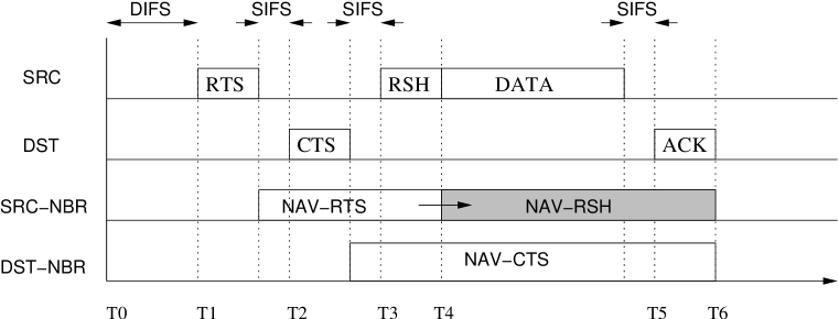
In the normal mode of operation, the IEEE 802.11b MAC uses a Distributed Coordination Function (DCF) for media access. DCF is an implementation of CSMA/CA protocol which follows the 4-way handshaking protocol for data transmissions. In DCF, whenever a node is ready to transmit data, it senses the channel to be idle for a period of Distributed Inter Frame Spacing (DIFS). Following this, it generates a random backoff timer chosen uniformly from the a [0, -1] where is the contention window. Initially the contention window is set to (16 for 802.11b). After the backoff timer expires, the node sends a short Request To Send (RTS) message to the intended receiver of data. If this message is received properly by the receiver and if it is able to receive any transmission, it responds back with a short Clear To Send (CTS) message. A node may not be able to receive any transmission if some other node in its vicinity has already reserved the channel for packet reception or transmission. Both RTS and CTS messages carry the duration information for which the channel is going to be occupied by the proposed data transmission. Upon hearing RTS and CTS, all other nodes in the vicinity of the sender and receiver update their Network Allocation Vectors (NAVs) with the information about the duration for which the channel is going to be busy. NAV is essentially a channel reservation vector. Thus, all nodes in the vicinity of the sender and receiver defer their transmissions and receptions to avoid collisions. The CTS message is followed by the DATA transmission which is acknowledged by the receiver by sending an ACK message if the DATA is received successfully. The data is repeatedly retransmitted in the absence of ACKs till a threshold number of retransmissions are carried out. Once the retransmissions exceed the threshold, the transmission is assumed to be unsuccessful. After an unsuccessful transmission attempt, the sender follows a binary exponential backoff (BEB) and doubles its contention window size. This is done in order to reduce the channel contention between nodes. The contention window is not incremented further if it already equals (256 for 802.11b). After every successful transmission, the contention window is reset back to . RTS,CTS,DATA, and ACK are separated by a time spacing of Short Inter Frame Space (SIFS). A timeline for DCF message exchanges is shown in Figure 1. The sense period of DIFS is always larger than SIFS. This ensures that no new transmission attempts interfere with the ongoing transmission.
DCF provides a mechanism for collision avoidance by performing a virtual carrier sense through RTS-CTS message exchanges. This is necessary to solve the hidden node problem. However, a node may chose to resort to a 2-way handshaking mechanism where data packets are transmitted without RTS-CTS message exchanges. The packet is acknowledged back by the receiver by responding with an ACK message. This mechanism can be used for small packets where the overhead of RTS/CTS message exchange can be traded off for small probability of collisions.

2.2 Link Management
Apart from channel access mechanism, 802.11b also provides additional facilities such as power save features, security etc. Moreover, 802.11b MAC is a distributed entity where decisions regarding various activities are taken independently at various nodes. To distribute MAC level information among the constituent nodes, 802.11b defines several messages which are transmitted as link level frames. The frames that are exchanged between different nodes of an 802.11b network are classified into three categories as follows:
-
•
Management
-
–
{association, re-association, probe}{request, response}, and disassociation: These frames are used for affiliation activity of any node to a particular cell and access-point.
-
–
authentication and de-authentication: These frames are used for security purposes.
-
–
beacon: This frame is usually sent by an access-point in infrastructure mode. In ad hoc mode, the first node to initiate an ad hoc network sends the beacon. This frame carries important management information like time-stamp, supported rates, traffic indication maps etc.
-
–
ATIM: Announcement Traffic Indication Message is a frame sent after every beacon frame. This is used by nodes utilizing the power save features of 802.11b to indicate their traffic pattern.
-
–
-
•
Control
The frames like RTS, CTS, ACK, PS-Poll (power save poll) CF-Poll, CF-ACK, CF-END (Contention free channel information in PCF) are categorized as control frames. -
•
Data
The data frames can be piggybacked with frames like CF-ACK, CF-Poll etc.
IEEE 802.11b also specifies a fragmentation mechanism using which an 802.11b node can divide data packets into smaller frames and transmit large packets when the frame error rates are high. The fragmentation threshold can be a configurable value or can be dynamically determined depending on the channel conditions.
To summarize, the 802.11b MAC layer provides, (1) Channel access mechanism, (2) Link management facility, (3) Rudimentary security, (4) Power management, and (5) Fragmentation.

3 Quality of Service
IEEE 802.11b WLANs provide best effort service similar to their wired counterpart Ethernet networks. Best effort service essentially indicates that every data packet handed over to the 802.11b interfaces receives similar treatment as other packets in terms of delivery guarantees. Thus, from an application perspective, it receives no Quality of Service guarantees from the network in terms of available bandwidth, latency, jitters etc. Some applications like media streaming and conferencing are sensitive to packet latency and effective bandwidth characteristics of the underlying network. With the growing thrust on use of wireless networks for media streaming and conferencing, it becomes essential to provide a service that is not merely best effort service but a service that is deterministic at certain level. IEEE 802.11b WLANs are usually deployed as access networks to the wired infrastructures for mobile terminals as shown in Figure 2. In wireless LAN scenario, usually the media and conferencing servers reside in the faster and reliable wired domain, whereas, the clients reside in wireless domain exploiting the mobility features. Thus the importance of QoS is relatively higher in the infrastructure setup rather than the peer-to-peer setup.
On the wired network, IETF’s Integrated Services [4] and Differentiated Services [5, 6] architectures are available to support guaranteed QoS and traffic prioritization respectively above the link layer. IEEE’s 802.1p is a layer 2 traffic prioritization standard for switched Ethernet environments. However, there are very limited QoS solutions that exist for wireless LANs, particularly 802.11b networks.
3.1 Point Coordination Function
IEEE 802.11b standard provides a very rudimentary support for quality of service in its infrastructure mode of operation. This support is provided by the MAC layer in terms of Point Coordinated Function (PCF). PCF is a MAC coordination facility that may exist on access-points to differentiate between the traffic flows from different nodes. PCF is an optional capability for access points and its implementation is not mandatory. Very few commercially available access-points for 802.11b networks actually provide this facility. Moreover, there are no clear mechanisms for individual nodes to participate in PCF and exploit the quality of service mechanism provided by it.
PCF provides a very rudimentary form of QoS by allowing nodes to transmit frames in a contention free manner. The access-point of a cell acts as a coordinator called the point coordinator (PC) for that cell. All nodes in 802.11b network obey the medium access rules of the PCF, since these are based on DCF which is followed by all nodes. The PC grants a contention free channel access to individual nodes by polling them for transmissions. On being polled, a node transmits a single frame destined for any node in the network. All nodes which need some quality of service are termed as CF-Pollable nodes. A node becomes CF-Pollable by indicating its interest in being polled during its association with an AP (PC). This results in the node being included in a CF-Pollable list maintained by the PC. A node can withdraw itself from polling process by performing a re-association.
In infrastructure mode of 802.11b, the time is divided into periodic superframes which start with the so-called beacon frames. A beacon frame in 802.11b is a management frame sent by an access point to carry out time synchronization and deliver protocol related information to all nodes. Beacon frames are periodically sent by the access points regardless of PCF functionality. Each superframe is divided into two units, namely, Contention Free Period (CFP) and Contention Period (CP). CFP is the period when contention free channel access is provided by the PC to individual nodes. CP is the period when all nodes contend for the channel using DCF. If the PCF functionality is not provided by the access point then entire superframe is the contention period. The extent of division of a superframe into CFP and CP is determined by the PC which can be arbitrary, but it is mandatory to have a CP of a minimum duration that allows at least one node to transmit one frame under DCF.

Figure 3 shows the activity of a wireless network during a superframe. At the beginning of superframe the PC waits for a period PCF Inter Frame Space (PIFS) and then transmits the beacon frame. If the PC supports PCF and the list of nodes that are interested in being polled is not empty, the PC sends a CF-Poll (or DATA+CF-Poll) frame to one of the nodes after waiting for channel to be idle for SIFS. In response, the node can respond with a DATA + CF-ACK or just CF-ACK if no data is ready to be sent. The response is sent after sensing the channel to be idle for an SIFS period. If there is no response to CF-Poll frame, the PC sends CP-Poll to next node after waiting for an idle period of PIFS. At the end of CFP, the PC sends a CF-END frame to begin the contention period using DCF. Thus in CFP, each polled node transmits frames in a contention free manner. In CFP, RTS/CTS handshaking is not carried out. During the entire CFP the PC is in control because it accesses channel after sensing the channel to be idle for PIFS duration. PIFS is much smaller than DIFS which is the period for which every nodes in DCF should sense the channel to be idle. The shorter duration of PIFS compared to DIFS ensures that no node can contend for the channel except either the PC or the node that has been recently polled.
There are several problems with PCF that make it less attractive for QoS utilization. First and foremost, there is no guarantee of bandwidth or any other QoS parameters except a contention free transmission of a single frame. The channel share available to individual nodes cannot be specified and it decreases with an increase in the number of pollable nodes in the network. Second, there is no definite bound on next poll being received by a node. The polls received from PC for a node may not be periodic. For flows with tight delay bounds and periodic traffic, this may be unacceptable. Third, there is no guarantee that the superframe itself is periodic. This is because the PC must sense the channel to be idle for PIFS duration before sending the next beacon. If the transmission of last frame from the previous superframe is prolonged then the beacon transmission may not be strictly periodic. Fourth, the size, rate and transmission time occupied by each frame is not constant. Some frames may be fragmented and may be arbitrarily long (upto 2312 bytes) and hence may take longer than usual transmission time. This will affect subsequent nodes. Some of the nodes may not be polled in a particular superframe. In short, there is no clear admission control and usage policy. Last, there is no clear way of interfacing an application with this mechanism. This makes PCF a facility with no use.
3.2 Rether for IEEE 802.11b
If one were to revamp PCF and come up with a scheme that is tailored to
provides QoS to applications, following enhancement would be required.
Interface: There must be some interface through which an application
can specify its bandwidth requirements to the underlying QoS mechanism.
Admission Control: There must be some admission control criteria so that the
available meager resources, once granted to certain applications, are not hijacked back.
Periodicity: The channel access must be provided in a fairly periodic fashion
for delay sensitive and periodic traffic.
Isolation: Once an application (or its flow) is admitted, the service
provided to it must not be affected by quirkiness of other applications and nodes.
Bandwidth Guarantee: The channel access granted should reflect into an appropriate
bandwidth guarantee over a long term duration.
Rether [7] is a QoS mechanism for 802.11b networks which provides bandwidth guarantees to individual flows. Rether borrows many salient features of PCF and is a software solution residing in the network stack of individual nodes. Rether addresses all of the above issues. In addition, it does not require any changes at the MAC layer and does not use the PCF capability which may not be available with every access point.
Like CFP and CP in PCF, Rether also has a notion of Real-Time (RT) and Non Real-Time (NRT) periods. Analogous to the superframe, Rether has a concept of a periodic cycle which corresponds to one set of RT and NRT period. Rether strives to guarantee a contention free channel access to all nodes during both RT and NRT period. During RT period, the channel access is granted to nodes with bandwidth reservations, and the NRT period is used to grant channel access to all nodes in the wireless network. Similar to the mandatory requirement of CP in PCF, Rether also has a notion of RT limit of bandwidth reservation beyond which no new flows are granted bandwidth guarantees. This is done to avoid the starvation of flows with no bandwidth reservations. Rether grants channel access to individual nodes by sending so-called tokens. The individual nodes signify their end of transmission by sending and explicit acknowledgment. Rether grants contention free channel access even in NRT period by circulating the token in a round robin fashion among the nodes without any bandwidth reservation. In order to avoid fairness issues, the round robin nature is persistent across consecutive NRT periods.


As depicted in Figure 5, Rether is implemented as a software module which resides between the IP layer and the device driver for the wireless interface. It intercepts all the packets that are handed over to the device driver and exercises control over their transmission which follows established QoS policies. Rether follows a client-server architecture. In an infrastructure wireless LAN, the Wireless Rether Server (WRS) is co-located with the access point. All nodes in the network understand the Rether protocol and are termed as Wireless Rether Clients (WRC). The WRS is primarily responsible for admission control and channel coordination.
Rether uses implicit bandwidth reservation mechanism based on port signaling. The advantage of this mechanism comes from compatibility with legacy applications which cannot be modified to carry out explicit reservation requests. The reservation mapping is specified in system policy files in terms of quintuples like :
{SrcAddr/Mask, DstAddr/Mask, SrcPrtRange, DstPrtRange, BW}
Rether module intercepts all outgoing packets on a node. Upon intercepting the first packet corresponding to any flow, the WRC sends a reservation request to the WRS if a corresponding policy specification exists. If the request is accepted all packets corresponding to the flow are maintained in a separate queue. The WRS circulates the token among all nodes who have established reservations. All WRCs dispatch packets from their queues according to the bandwidth requirements upon reception of tokens. The dispatching is limited to bandwidth share or allocated slice of the cycle which ever occurs first. This limitation helps in providing isolation between nodes with bad radio characteristics and normal nodes. Once all nodes with reservations are served, WRS switches to NRT mode and the clients without any reservation are provided with tokens in a round robin fashion.
With this architecture, Rether provides an effective bandwidth guarantee scheme which can be readily used by applications. The guarantees are provided by granting a contention free channel access to all nodes transmitting packets. Further, Rether is an all-software protocol which does not need any modification to the underlying MAC layer.
3.3 IEEE 802.11e
The market thrust on wireless LAN technologies and the requirement of QoS support in these networks has led to the establishment of an IEEE standardization working group to enhance 802.11 to provide applications with QoS support. Upcoming standard 802.11e tries to address the QoS problems faced by wireless LANs based on 802.11 specifications.
The QoS support in 802.11e is provided in two forms. First, it supports a priority based best-effort service similar to diffserv. Second, it supports parameterized QoS for the benefit of applications requiring QoS for different flows. 802.11e achieves this by enhancing the 802.11 DCF and PCF functionality, and by providing a signaling mechanism for parameterized QoS.
The enhanced MAC protocols in 802.11e are EDCF and EPCF. Both EDCF and EPCF are commonly refered as the Hybrid Coordinated Functions (HCF). The priority based best effort service is provided by the EDCF. This is done by introducing so-called traffic categories. Frames corresponding to different traffic categories are now transmitted through different backoff instances. Each traffic category has an associated independent backoff instance. The scheduling of frames for every traffic category is done the same way as in DCF. The differentiation in the priority is achieved by setting different probabilities for different categories for winning the channel contention. The probability is changed by varying the so-called Arbitration Inter Frame Space (AIFS) which is the listen interval for channel contention. AIFS is analogous to the DIFS period in DCF. For each traffic category, the value of AIFS determines the priority. With lower AIFS values, the listen interval required for channel contention is lower and hence the probability of winning the channel contention is higher. For compatibility with legacy DCF, AIFS should be at least equal to DIFS. The backoff procedure in case of collisions is similar to that in DCF. The main distinguishing factor is the method by which the contention window is expanded after collisions. In DCF, the contention window is always doubled. Whereas in EDCF, the contention window is expanded by a predetermined persistence factor (PF). For example, in DCF scenario the PF is always 2 since the contention window is always doubled.
A single node can have upto eight traffic categories. These different categories are realized as eight different virtual nodes with varying parameters, such as, AIFS, CW, and PF. These parameters are responsible for determining the priority of each traffic category. If the backoff counters of multiple traffic categories reach zero at the same time, there is a virtual collision within the same physical node but different traffic categories. This is resolved by a scheduler inside the node by allowing transmissions from the traffic category with the higher priority.
Another enhancement in 802.11e is the concept of a transmission opportunity (TxOP). TxOP is defined as the interval during which a node has the right to initiate transmissions. Thus, a node can initiate multiple transmissions as long as its TxOP has not expired. The value of EDCF-TxOP is unique throughout the network.
IEEE 802.11e also facilitates parameterized QoS. This is provided by the enhanced version of PCF (EPCF). The HCF has a notion of Hybrid Coordinator (HC) similar to the PC in PCF. The HC can allocate TxOP to itself or any other node at any time but after sensing the channel to be idle for a duration of PIFS, which is shorter than DIFS. This ensures that the HC has the highest priority over all other nodes at any given time. The HC allocates TxOP to pollable nodes in contention free periods and sometimes even during contention periods. The main distinction between PCF and HCF is that in PCF a node can transmit only one frame after receiving CF-Poll frame. In HCF, a node can initiate the transmission of frames till the end of TxOP. The duration of TxOP is notified to the node using the Poll frame sent by the HC. To provide TxOPs with appropriate duration and appropriate time, the HC needs to obtain the pertinent information from the individual nodes from time to time. For this purpose, the HC initiates the so-called controlled contention periods during which nodes send their resource requests to the HC without contending with other nodes which are sending only data traffic. There can be eight more traffic categories for parameterized traffic in addition to the eight EDCF categories. The frames queued in these categories are transmitted after receiving poll frames from the HC. Thus, at most eight flows on any node can be provided parameterized QoS. The flows are identified by source and destination MAC addresses.
S. Mangold et al. [8] present a comprehensive overview of these features. They evaluate various QoS support features by means of simulations. The simulations were mostly for 802.11a network (a higher speed version of 802.11 operating at 5GHz band). They analyzed the behavior of EDCF for different categories (mainly high, medium, and low priorities) and the measured throughput performance against the offered load. The simulation results obtained were consistent with the expected results. For high priority traffic the throughput increased linearly with the increase in offered load. Whereas, the low and medium priority traffic observed knee points after certain level. The knee point of low priority traffic appeared ahead of medium priority traffic. They also evaluated the performance of HCF for parameterized QoS. The metric chosen was the service delay for frames. The results were consistent with expectations. The delay probability decreased for higher values. Almost all the time the delay was within fixed bounds. The evaluations showed that the enhanced MAC protocols indeed provide the expected QoS which is the main objective of 802.11e.

One of the major issues with QoS provisioning is how to percolate the QoS related information to pertinent layers. For example, the QoS requirements are mainly application specific requirements, whereas, the actual bandwidth provisioning has to be done at the MAC layer in the LAN. This issue calls for a coordination between the MAC and higher layers so that the applications can request their QoS requirement in an appropriate manner. For this purpose, 802.11e defines two entities; Station Management Entity (SME) and MAC Layer Management Entity (MLME). SME is a logical entity in a node which is capable of communicating with all layers in the network stack, whereas, MLME deals with interacting with SME and managing MAC layer. The SME and MLME communicate with each other by means of intra-STA signaling. Different MLMEs in an infrastructure network communicate by means of inter-STA signaling. For example, the communication between HC and a node regarding TxOP duration etc. is part of the inter-STA signaling. The inter-STA signaling is used to setup, modify, and delete traffic streams. This signaling carries a traffic specification (TSPEC) element to characterize the QoS requirements of a node. As shown in Figure 6, TSPEC carries various information like minimum data rate, burst size, etc., which can be derived directly from higher layer requirements. Whereas, some fields like polling interval, retry interval, etc., are more MAC layer specific. Since SME is capable of interacting with all protocol layers, it is capable of obtaining QoS requirement for specific flows. These requirements are then conveyed to the MLME which is responsible for establishment of final reservations. Sai Shankar et al. [9] describe the QoS signaling procedure for parameterized traffic in the purview of RSVP.
As of beginning of year 2003, the 802.11e is still a draft and has not been standardized yet. The QoS mechanism seems to be geared more toward RSVP. (TSPEC is mostly RSVP specific). The draft is continuously being revised. For example, there are some documents which indicate that the TSPEC element is being replaced with a new Queue State element [10].
4 Fairness
Wireless channel is a shared scarce resource. The MAC protocols used over wireless networks are distributed protocols which try to avoid collisions and provide the nodes in a network with an access to the channel in a fair manner. The efficiency of MAC protocols can be measured using two parameters: the probability of collision and fairness in the allocation of channel to competing nodes. The wireless LAN protocols, like any other randomized multiple access protocols, try to resolve the collision problem by following a binary exponential backoff (BEB). BEB is a very efficient mechanism in terms of reducing collision probability. It often reduces the collision probability to a fraction of transmissions, as low as 1%.
Typically all variations of CSMA/CA protocol suffer from the fairness problem investigated first by Bhargavan et al. [11]. A channel access protocol (MAC) is termed to be unfair if it fails to provide the channel access to individual nodes without giving preference to one node over others when there is no explicit differentiation. That is, when multiple nodes in a network are competing with each other for channel access, the probability of each node winning the contention should be equal.
Though the wired Ethernet protocol based on CSMA/CD is known to be fair, its wireless counterpart 802.11b based on CSMA/CA is proven to be unfair [12]. The unfairness of wireless networks has roots in the fact that unlike wired networks, the collisions in wireless networks are asymmetric. It is not necessary in wireless networks that all nodes involved in collision suffer from packet loss. The collisions and hence the binary exponential backoff can occur primarily because of the following three reasons.
-
•
Transmissions from two nodes interfere with each other and hence their transmissions do not get acknowledged. The absence of ACKs is then treated as collisions by both the senders.
-
•
In the 4-way handshaking mode, if a node does not receive CTS response for its RTS request, it treats this as a collision and hence doubles its backoff window. This is irrespective of the status of the destination node. A node may defer to send back CTS if any other node in its vicinity has reserved the channel by sending an RTS or CTS to some other node.
-
•
If two nodes carry out simultaneous transmissions intended for the same destination, one of them may succeed because of higher power level. This is called the capture effect in wireless channels [13].
Out of these three collision scenarios only the first one is the real collision. The other two scenarios result in success for one node and failure for the other. In this case, only the failed one performs the binary exponential backoff. For subsequent channel contention, the node which succeeded recently has a higher probability of winning the contention because of its lower backoff window. This is essentially because of the dissimilar congestion view about the channel by different nodes. Nodes which are generally successful in accessing the media perceive it to be less congested compared to the nodes which encounter failures. This prompts the successful nodes to access the channel in a more aggressive manner (because of lower backoff window) than the failed nodes. This skewed notion of congestion leads to an unfair access of the channel.
The dissimilarity in wired and wireless networks arises because of the dissimilar nature of the media. In wired networks the media is indeed a shared media. If one node is accessing/using media all other nodes are aware of the media access. But the wireless media is a piecewise shared media. The reach of each node is limited by the transmission power and the local noise present in the region. This makes the media characteristics location dependent and hence a non-uniform nature of the media is perceived by constituent nodes.
The backoff procedure used in almost all wireless medium access protocols is essentially borrowed from the wired Ethernet where the non-uniform nature of media does not exist. So, the binary exponential backoff procedure which provides a fair media access in wired networks becomes the cause of unfairness in the wireless networks.
4.1 Impact of Unfairness
The unfairness of MAC has a far reaching impact on the behavior of higher layer protocols and the applications using the network. Application like audio/video streaming are sensitive to packet delays and jitters. When the underlying link behavior is unfair, some applications may be starved of bandwidth just because their share is unfairly distributed somewhere else.
Shugong Xu et al. [14] analyze the behavior of TCP protocol in multihop 802.11 networks. Using simulations they show that TCP suffers from instability and unfairness problem in these networks. The instability causes the throughput of available wireless network to fluctuate because of interactions between different nodes carrying TCP-data and TCP-ACK traffic. The unfairness problem leads to indefinitely long timeouts causing multiple retransmissions and route breakups.
Koksal et al. [12] describe a scenario where TCP performance degrades because of short term unfairness exhibited by MAC protocols. Because of short term unfairness the TCP acknowledgments fail to reach the sender in a timely fashion. This results into a bursty traffic. This bursty traffic results into and ACK compression which aggravates the burstiness of the stream. The bursty traffic has many disadvantages like packet loss in response to bursty traffic and throughput loss because of idle links during two consecutive bursts.
4.2 Achieving Fairness
Since the fairness problem is deep rooted in the MAC layer itself, it is reasonable to conclude that it can be solved by modifying the MAC in an appropriate way that achieves fairness. To this effect there have been several enhancements and modifications suggested to the MAC layer. Some of the examples are MACAW [11], Estimation based backoff [15], Distributed Wireless Ordering Protocol [16], and Distributed Fair Scheduling [17].


MACAW
Vaduvur Bhargavan et al. [11] observe that to allocate media fairly, congestion level estimation should be a collective effort. In other words, the propagation of congestion information should be explicit rather than each node learning it on its own.
MACAW tries to address the fairness issue in single cell scenarios as depicted in Figure 8. In this setup there are 3 nodes N1, N2, and N3 which are trying to transmit data to another node B (base station) in same cell. If the transmission queues of all the nodes are backlogged then most of the times all of them are contending for the channel access. If during the contention all but one pad have relatively high backoff counters then the one with low backoff counter will win the contention. This will result in that node resetting its contention window to the lowest possible window size. This will put the successful node at an advantage over the other nodes since it has now a more than fair chance of winning the contention at later time. This will result in increasing the contention windows of other even further. Note that, in this scenario the implicit assumption is that the other nodes do not perform carrier sense and do not freeze their backoff counters for the duration of transmission.
The observation to be made here is that the backoff counter (or the contention window) of a node does not reflect the ambient congestion level that exists in the entire network. MACAW advocates sharing of this information by all the nodes in the network. This can be done by including the value of current contention window in every packet that gets transmitted. All other nodes can now update their contention values depending on the latest notified value. Thus, in a network where all nodes are within the reach of each other, after every transmission all nodes have same contention window.
This scheme solves the problem of information sharing but introduces a new problem of oscillating contention windows. After every successful transmission, the contention window gets reset to the minimum possible value. If the number of nodes in a network is very high, all nodes would spend a lot of time adjusting their contention window to reach an optimal level which would be immediately reset after a successful transmission by any of the nodes. MACAW deals with this oscillation problem by introducing a multiplicative increase linear decrease (MILD) backoff algorithm. In this algorithm the backoff window is increased by a multiplicative factor after collision and is decreased by 1 after success. The multiplicative increase yields a prompt convergence to the backoff window when the contention is high and avoids oscillations by not resetting it to the minimum possible value.
MACAW does not assume that the nodes use carrier sense to avoid collisions. In a single cell network, the fairness problem does not exist if nodes perform carrier sense and freeze their backoff counters for the duration of transmission by other nodes.
MACAW also tries to address the issue of proper definition of fairness. If the fairness criteria is defined as,“equal channel share for every node,” then there are certain nodes like base stations in infrastructure networks which are at a disadvantage. Consider the setup shown in Figure 8. Here the base station B needs handle streams to nodes N1 and N2. Node N3 needs to send data to the base station. In this scenarios there are only two nodes which need to access the channel. If the channel access is granted equally to N3 and base station then the channel share is not fair from the perspective of streams. MACAW suggests that this problem can be solved by running multiple instances of backoff algorithm each corresponding to a stream. As a matter of fact, this scheme is the basis of traffic categories in 802.11e.
Estimation based backoff
Zuyuan Fang et al. [15] propose a novel measurement and estimation based scheme to solve the fairness problem in 802.11b networks. The proposal is based on estimating the throughput of all nodes and then computing a fairness index based on this estimation. This fairness index can then be used to adjust the contention window.
The fairness index between any two nodes and is computed using the following equation:
| (1) |
where is the predefined fair share that a station i should receive and
is the throughput achieved by node i. The constraints on and
are such that for a total throughput of W :
= 1 and = W
The fairness goal now becomes maximizing the value of fairness index locally. When the fairness index equals 1 all nodes obtain the throughput proportional to their share. There are two issues with this approach. First, how to predefine the fair share of each node. Second, how to measure the total usage by all nodes. Note that the algorithm should take into account the hidden nodes and node mobility as well. Thus, there cannot be any signaling traffic between the nodes.
The solution to the first problem is achieved by dividing the nodes into two partitions. In this approach, each node regards all of its neighbors as a single entity with a notion of myself and the others. Now the fair share assumed by each node is = 0.5. All other nodes also get the remaining share of 0.5. The assumption here is that when all nodes use the same approach, all of them will compete with same fair share. Thus due to the local contention and collisions the long term throughput will achieve fairness. If one wants to provide a stream based fairness, a node can increase its fair share by the proportional amount. That is, if a node has two streams then it treats streams of all other nodes as a single stream and computes its fair share as = 0.67.
The second problem is solved by snooping on the traffic in the network. A node can always measure its own traffic. The traffic from hidden nodes is deduced by snooping on the CTS and ACK packets sent to those nodes.
Once a node has an estimate of its own traffic and the traffic by others it computes the fairness index using the above mentioned equation. After computation of the fairness index it doubles it contention window if it has obtained more than its fair share and halves it if it has not received its fair share.
The effectiveness of this approach essentially depends on the approximation of the fair share . if the value of is higher than what it ought to be, the node acts in a greedy fashion and the short term fairness of the channel allocation is affected. For a network with competing nodes, the share should be . The farther the assumed value (0.5) from , the greedier is the algorithm. This greediness of algorithm, though ensures the long term fairness, affects the short term fairness severely. Moreover, the IEEE 802.11b MAC is known to be fair in long term and it is the short term fairness one needs to address. This can be possibly done by estimating the number of nodes in the network. If the estimation of number of nodes is close to the actual number of nodes, the algorithm can work very efficiently.
Distributed Fair Scheduling
Nitin Vaidya et al. [17] extend the notion of fairness to include the weight of a flow for considering its share of the channel. This is in contrast with the prevalent notion of equal share to all nodes or equal share to all flows. They propose an extension to 802.11b DCF to achieve this Distributed Fair Scheduling (DFS) with weighted proportions. The DFS was designed in an attempt to emulate the Self-Clocked Fair Queueing (SCFQ) [18]. The DFS is specifically tailored for distributed systems like 802.11b LANs.
SCFQ is a centralized algorithm for packet scheduling on a link shared
by multiple flows as shown in Figure 10. The central
coordinator maintains a virtual clock. At any given time t,
v(t) indicates the virtual time. Assume that :
denotes the packet arriving on flow, is the
real time of arrival for packet , and represents the size
of the packet . For each packet , a start tag and a
finish tag are assigned. The assignment algorithm is as follows:
-
1.
i = .
-
2.
Every packet is stamped with start tag using following equation:
= max {v(), }. -
3.
A finish tag for each packet is calculated as:
= + .where is the bandwidth share of the flow i.
-
4.
Initially at time = 0, the virtual clock v(0) is set to 0. The virtual time is updated after every packet is transmitted. At the end of the transmission of packet , the virtual clock is set to .
-
5.
Packets are selected for transmission in an ascending order of finish tags.
Alternatively one can assign the start tag for a packet based on
the real time when it is advanced to the front of the queue. If the
packet arrives when the flow is empty the the time =
is the real time when the packet is advanced to the front of the queue,
else is the real time when the packet finishes the
transmission. Thus the start tag for a packet can be assigned in a lazy
fashion by following equation
| (2) |


Like SCFQ, DFS determines the packet transmission times based on the finish tag of each packet. Further, the virtual time is updated in the same way as SCFQ. DFS tries to map the shared wireless medium to the output link and input flows paradigm of SCFQ. As shown in Figure 10, the output link in Figure 10 is mapped to the shared wireless medium and the input flows are mapped to the flows from each individual node.
SCFQ is a centralized algorithm. Because of this centralized nature, there is no issue in determining the shortest of the finish tags of the packets from each queue. But in DFS all queues are distributed. Thus, the selection of next eligible packet for transmission has to be done in a distributed manner. DFS circumvents this problem by choosing the backoff interval proportional to the finish tag of the packet that is at the front of the flow. Further, each transmitted packet carries the virtual finish time of the packet each transmitted packet carries its virtual finish time with it. This virtual finish time is used by other nodes to synchronize their virtual clocks.
DFS is implemented as follows:
-
•
Whenever a packet advances to the front of the flow, its start tag is updated depending on the virtual time at that instance.
-
•
The virtual finish time for every packet is calculated similar to SCFQ but with a scaling factor for choosing a suitable scale for virtual time. Note that = v() and from equation (2):
(3) -
•
Using this virtual finish time a backoff interval is picked for the packet :
= - v()
Using equation (3) we get:(4) -
•
This backoff window is further randomized by multiplying it with a random variable with mean 1.
On close observation, it becomes apparent that there is no need to maintain a virtual clock as the virtual finish time is never used in calculating the backoff interval. After every packet transmission on LAN, all nodes calculate the backoff interval based on the fairness share of each node and the packet size. DFS deals with collisions the same way as 802.11b, i.e., the binary exponential backoff. Thus only first backoff interval is chosen depending on the fairness share of the node and is a linear function of packet size and fairness share. If the fairness share is very small, there might be long duration of idle time because of this linear nature of backoff interval. If the number of nodes in the network is high, this might lead to dropped throughput of the network because of excessively long backoff intervals. This problem is circumvented by compressing larger backoff intervals into smaller exponential range. It is not clear how the channel shares is assigned to each node.
5 Performance
Throughput performance of communication links is measured in terms of observed data rates. Looking from the link layer perspective, the performance is the effective data rate available for the raw bits exchanged between nodes. Whereas, looking from the network layer perspective, it is the rate at which the network layer data is exchanged. This precludes the management data exchanged at the link layer. As one moves higher up the protocol stack, the performance of a link progressively reduces. The reason for this progressive performance reduction is almost always associated with lower level protocol overheads. Further, for shared media like wireless channels, where multiple nodes contend for the same channel, additional channel bandwidth is used up to resolve the contention and some bandwidth may even be lost when collisions arise.
5.1 Performance Loss
For wireless networks like 802.11b, it is never possible to achieve the
theoretical available bandwidth at the application level. Since a wireless channel can
never be devoid of noise, the first loss is at the physical radio link itself.
Shannon’s equation gives the relation between available data rate for a channel
with bandwidth with a Signal to Noise Ratio (SNR) as :
=
This is the theoretical limit and there can be additional loss because of multipath fading, Doppler shifts, and bit errors [19].
The second rung of reduction in throughput occurs at the Physical layer. An 802.11b frame is shown in Figure 11. Each frame comprises of 24 bytes of Physical Convergence Protocol Layer (PLCP) preamble and header. This PLCP preamble is then augmented with rest of the MAC Protocol Data Unit (MPDU). The header is always transmitted at a slower rate of 1 Mbps and rest of the MAC Protocol Data Unit is transmitted at a variable rate. This slow rate transmission is necessary for compatibility and reachability with all nodes in the network. Thus, a significant portion of transmission occurs at the lower data rates causing a reduced throughput.

IEEE 802.11b uses CSMA/CA [3] protocol for media access. In this protocol each data packet transmission is preceded by a channel reservation request (RTS) and a channel reservation response (CTS) between sender and receiver. The data packet is then followed by an acknowledgment from the receiver (ACK). The ACK is required for the reliability of link level transmissions. The transmission follows the so called 4-way handshake protocol of RTS–CTS–DATA–ACK in order to solve the hidden node problem. The additional bandwidth consumed by these RTS/CTS/ACK and several other management frames add up to the reductions in performance throughput.
The observed data rate for 802.11b networks by network layer is around 7 Mbps in typical indoor environments and the bandwidth of 802.11b networks is 11 Mbps. The next level of performance loss is because of complex interactions between protocol layers and other overheads. We will be examining some of the protocol performance issues.
5.2 Performance of TCP
Performance of TCP/IP over wireless networks is a widely researched topic. TCP behavior is studied under various flavors of wireless environments. The primary thrust of this research is on the behavior of TCP in response to the error conditions in wireless networks. TCP, which is known to be a very stable and robust protocol on wired networks does not perform as well on wireless networks. Some of the serious issues with TCP are that of performance degradation over wireless links. The primary reason for performance degradation is the assumption by TCP that all losses in the network are due to congestion [20].
In almost all wireless networks, the transmissions are highly prone to frame errors which increase with packet size. For example, in 802.11 networks, the Frame Error Rate (FER) doubles for every 300 byte increment in frame size [21]. Thus, at higher packet sizes, the frame errors are higher and hence the packet loss is higher. This packet loss is wrongly treated as congestion by TCP and its congestion control mechanism is triggered. As a result, TCP reduces the congestion window size. The TCP congestion window size is the number of packet that can be sent with outstanding acknowledgments. Congestion window is the measure of minimum number of packets required to keep the link occupied increasing the channel utilization. This congestion control causes lower channel utilization even though in reality there is no congestion in link.
One of the first proposed solutions for TCP performance degradation on wireless links is Indirect-TCP (I-TCP) by A. Bakre et al. [22]. I-TCP works by splitting the transport connection at the wired-wireless boundary, usually on base stations. I-TCP maintains two separate TCP segments, one is over the wired network between the base station and the wired end of TCP connection, the other is over the wireless between the base station and the wireless host. This way, the losses occurring on wireless network are hidden from the wired nodes. To cover up for the losses on wireless segment the base station carries out retransmissions. Though an efficient solution, this approach violates the end-to-end semantics of TCP. For example, in this approach even if the sender receives an acknowledgment, it does not mean that the receiver has indeed received the packet. This violation of end-to-end semantics can have serious impact on applications. It may so happen that the wireless host may crash before it receives the packet that has been acknowledged by the base station. This is against TCP semantics and may not be acceptable to certain applications.
Hari Balakrishnan et al. [23] try to address this problem by proposing a snoop module that resides in the routing protocol stack of the base station. This snoop module snoops on all the packets that are sent to the mobile hosts and the acknowledgments that are transmitted by the mobile nodes. It also caches the packets that are transmitted over the wireless network. This enables the base station to detect packet losses in the wireless network and to retransmit the lost packets, thus avoiding the triggering of TCP’s congestion control and avoidance mechanisms.
The 802.11b provides a fragmentation oriented solution for this at the MAC layer. Since the frame error rate increases with frame size, the reliability of transmissions can be increased by reducing the frame size. Al most all 802.11b network interface cards support an option of enabling the fragmentation. In the event of bad channel conditions and increased frame errors, the MAC unilaterally fragments the larger frames into smaller frames of optimal size. This is done in a manner transparent to the higher layers. The receiving node then defragments the frames to obtain a complete data packet which can be handed over to the higher protocol layer. Since the fragmentation occurs at the frame level, there is no higher protocol overhead associated with the fragments. There is a small overhead of additional MAC header. Compared to the alternative of loosing the frame and reducing the overall throughput, a small overhead is a fair trade off.
Another problem with TCP in wireless LANs is that of Self Collision. George Xylomenos et al. [24] describe a scenario where the TCP data packets contend for the channel with the ACKs for the previous packets. This contention results in self collision for the TCP connection causing overall performance to degrade. This self collision is caused because of the half duplex nature of wireless networks. Haitao Wu et al. [25] propose a modification (described in section 5.3) to the Distributed Coordination Function (DCF), which is the MAC protocol for 802.11b, to alleviate this self collision problem.
Typically most of the solutions for the issues faced by higher protocols like TCP are localized solutions. The problems are tackled within a protocol layer and no effort is made to make other protocol layers aware of the changing situation. While this transparent approach is good from modularity and simplicity of design point of view, it severely impacts the performance. It is evident that in order to optimize the network performance, all layers in the protocol stack should adapt to the variations in the wireless link appropriately. Further, this should be done while considering the adaptive strategies at other layers [19].
Data Rate Code Length Modulation Symbol Rate Bits/Symbol 1 Mbps 11 (Barker Sequence) BPSK 1 MSps 1 2 Mbps 11 (Barker Sequence) QPSK 1 MSps 2 5.5 Mbps 8 CCK QPSK 1.375 MSps 4 11 Mbps 8 CCK QPSK 1.375 MSps 8
5.3 Performance Improvements
The performance improvement research for IEEE 802.11b can be broadly categorized into three classes based on the locality of the optimizations involved. These categories are mainly: MAC performance optimization, Network or Transport layer enhancements, and Infrastructural arrangements.
5.3.1 MAC Performance Optimization
Recent performance optimization research in 802.11b MAC aims at improving or enhancing the performance by modifying the MAC while retaining backward compatibility with existing specification. We give an overview of some schemes seeking to modify the DCF channel access protocol to bring in performance enhancements.
Multi-Rate 802.11b
IEEE 802.11b supports data transmission facility at multiple rates. These multiple data rates are possible because of different modulation techniques which are optimized for different channel conditions. Techniques like Quadrature Phase Shift Keying (QPSK), with 8 bit Complementary Code Keying (CCK) error correction codes, provide a bandwidth of 11 Mbps but need very high Signal to Noise Ratio (SNR) in channel. Whereas, techniques like QPSK, with 11 bit Barker Sequence, provide 2 Mbps of bandwidth but are capable of operating in noisy environments. Table 1 describes various data rate specifications for IEEE 802.11b.
Network interface Cards supporting these multiple data rates are capable of switching between different modulation techniques after assessing the channel characteristics. A user can choose to clamp the network interface at one particular rate or can enable the option of letting the device choose an appropriate rate. In order to improve the performance, the network interface cards can adapt to varying channel conditions and dynamically switch between different modulation techniques. This adaptation primarily involves two tasks, (1) sensing the channel quality and (2) selecting the appropriate technique and hence the data rate. Channel quality can be estimated by using several metrics, such as, signal to noise ratio, bit error rate, signal power, etc. A history of these metrics can be maintained which can be used to predict the channel conditions in future. But given the volatile nature of wireless channels, it is not clear how accurate and reliable these estimates can be. Using these estimates, one can select an appropriate rate for the estimated channel condition and transmit the data at the selected rate. For example, if the channel condition is excellent then the sender can select the highest possible rate for transmissions. On the other hand, if the bit error rate is high, the sender can choose to select a stronger encoding technique while dropping the rate. For worse channel conditions, the sender may resort to the lowest possible rate just to get the data across.
Auto Rate Fallback Scheme (ARF)
The channel quality estimation is a proactive approach and may not be accurate. Instead, one can implement a simple reactive channel quality sensing mechanism which gauges the changing channel conditions based on success or failure of previous transmissions.
In IEEE 802.11b, link level reliability is provided by explicit link level ACKs. Retransmissions are carried out if positive acknowledgments are not received. Lucent corporation’s Orinoco cards provide a simple result based Auto Rate Fallback (ARF) [26] mechanism which uses ACKs (or their absence) to estimate the channel quality. The ARF mechanism is a timer driven mechanism which keeps track of missed acknowledgments and works as follows. When an ACK is missed for the first time, after earlier successful transmissions, the first retransmission is carried out at the same rate. After second failure, the transmission rate is downgraded to the next lower data rate and a recovery timer is started. The transmission rate is upgraded back to the next higher data rate if the timer expires or 10 consecutive transmissions are successful. After this recovery if the very next transmission meets a failure, the system immediately reenters the fallback condition and resumes the normal operation.
While the ARF mechanism is good for link quality estimation between a fixed pair of nodes, it overlooks the fact that it is the receiver whose channel conditions need to be estimated and not the sender. A direct disadvantage of ARF scheme can be seen when there are multiple nodes communicating with each other in a wireless network. If a node moves to a location with bad radio characteristics, other nodes communicating with this particular node would experience transmission failures and as a result the transmission rate would be dropped. Consequently, it would take 10 successful transmissions or a timeout of the recovery timer to increase the data rate to the next higher level. This can result in pulling down the throughput for the entire network at lower data rates. If more than 10% of the nodes in a wireless network are in bad radio characteristics zone and the communication traffic between all nodes is more or less equal, the overall throughput of the network would always be clamped at the lower threshold. In addition, if some nodes are mobile and there are certain dark spots in the wireless network, the nodes moving in and out of dark spots would reduce the network throughput further. Thus, ARF would fail to perform efficiently in a network which comprises of zones with varying network characteristics. Which defeats the primary goal of ARF, that is to adapt to varying network conditions.
Receiver Based Auto Rate Scheme (RBAR)
Gavin Holland et al. [27] propose a rate adaptive scheme which uses feedback information from the receiver to sense the channel condition rather than estimating it at the sender. They also observe that in cellular networks, most of the receiver based channel quality estimation techniques have following characteristics:
-
•
Channel quality information is estimated by the receiver and periodically fed back to the sender either on same channel or on a separate channel.
-
•
The sender performs rate selection based on the feedback from the receiver.
-
•
The estimation, feedback, and rate selection schemes often reside at the physical layer and are transparent to the higher layers (such as, even MAC).
It is difficult to apply same techniques to wireless LANs because conventional wireless LANs usually operate in half duplex mode***For full duplex mode, one would need the receiver and transmitter on same card to operate simultaneously. The transmitter in this case would interfere with the ongoing packet reception. Hence most of the wireless LANs operate in half duplex mode.. This makes simultaneous feedback impossible. Moreover, wireless LANs use distributed contention based media access which need accurate time estimates for packet transmissions so that other nodes in the network can be informed about them. Dynamic encoding below MAC layer would hinder this operation and can impact efficiency.
Thus, one of the major problems in receiver based estimation schemes for wireless LANs like 802.11b is the requirement of a mechanism to provide feedback information to the sender. Another desired feature about the feedback is that it should convey instantaneous information rather than history to be more effective.
Since, IEEE 802.11b uses DCF for channel coordination, each DATA packet from sender is preceded by a short RTS packet. RBAR leverages on this RTS packet to estimate the channel quality and reception at the receiver end. Using this information the receiver selects an appropriate transmission rate. This rate information is then piggybacked on the CTS response to the sender. The sender then uses this information to carry out the actual transmission.
In 802.11b DCF, RTS and CTS packets carry the duration information for which all nodes should set their NAV. RBAR proposes to replace this duration information with data rate and the size of the data packet. Other nodes overhearing RTS and CTS can calculate the duration from this information and still set their NAVs to appropriate values.
The operation sequence and the 4-way handshaking for RBAR is shown in Figure 12. Whenever some node Src has some data to be sent to some node Dst, it performs the usual channel sensing for a period equal to DIFS. Once the channel is sensed to be idle for DIFS time it sends a short RTS message to DST. This RTS message carries the tentative transmission rate and the size information. Using this information, nodes in the vicinity of Src calculate the duration and set their NAVs accordingly. The node Dst upon receiving RTS analyzes it for its signal quality, strength and other metrics and selects an appropriate rate for the transmission. This selected rate and the size of data is again encapsulated in the CTS response. Nodes overhearing CTS response set their NAVs to appropriate values. The node Src, after receiving CTS response, selects the suggested rate and carries out the data transmission. In the event that the selected rate is different than the tentative rate, the nodes in the vicinity of Src who can not hear the CTS response also need to be informed of the change in the duration. For this purpose, RBAR prepends the DATA packet with a Reservation Sub Header (RSH) which informs other nodes of modified rate and size. This is used to modify the NAVs of hosts in the vicinity of Src. This way the data transmission is carried out with the rate suggested by the sender.
The overhead of RBAR comes in the form of the additional RSH frame. This frame is required when the actual transmission rate is different than the tentative transmission rate. The overhead is maximum when the data packet size is the smallest and decreases with an increase in the data packet size. The authors analytically show that even for small packets with size of 32 bytes RBAR outperforms ARF scheme by at least 10% in terms of the overall channel throughput. With increasing packet sizes, gains up to 20% are observed.
The gains are significant and the required modifications are relatively trivial. This makes RBAR approach a very elegant solution to deal with varying channel conditions. But RBAR heavily relies on a single RTS frame to infer the channel conditions and select the optimal rate. Further, in 802.11b, the RTS frame is always transmitted at the lowest possible rate so that all nodes can update their NAVs. Thus, a single RTS frame may be inadequate to infer proper channel characteristics.
Opportunistic Auto Rate Scheme (OAR)
B. Sandeghi et al. [28] propose an opportunistic media access scheme (OAR) which extends RBAR and tries to utilize the period of good channel conditions to maximize the network throughput. It exploits the fact that the coherence period for 802.11b networks is in the range of multiple milliseconds even at mobility speeds of 20 m/s. The Coherence period of a channel is the interval for which the SNR values do not decorrelate and the channel quality remains fairly unchanged. Thus the channel quality estimation done at an instance can be assumed to be valid for the duration of the coherence period. For 802.11b, this period corresponds to multiple packet transmission times. This enables OAR to rely on the signal quality information provided by the receiver and carry out multiple packet transmissions. The main idea of OAR is to exploit good channel conditions to transmit as many packets as possible while retaining the long term fairness provided by 802.11b. OAR achieves this by sending a burst of packets for a single RTS-CTS handshake. For this purpose, OAR suggests a modification to the 4-way handshake mechanism, which can be retrofitted into 802.11b DCF.
The number of packets transmitted by OAR in any transmission burst should be limited so as to provide a fair channel access to all nodes. OAR tries to achieve this by allocating a fair temporal share of the channel. The fair temporal share is determined as the maximum time the channel can be occupied if OAR were to transmit a single packet at the base rate. The base rate of a channel is the lowest possible rate with which data can be transmitted. The base rate of 802.11b channel is 2 Mbps. Thus the number of packets sent in every burst is equal to the ratio of sending rate and the base rate. Thus the burst is limited to at most 5 packets when the selected transmission rate is 11 Mbps. This guarantees that OAR inherits the same temporal fairness properties of original 802.11 base protocol [26].

In OAR, the transfer of a burst of packets is achieved by using the IEEE 802.11b fragmentation mechanism. Figure 13 shows the timeline for transmission of a fragmented data packet. Each fragment carries the duration information about the next fragment to update the NAVs of neighboring nodes. The ACKs for fragments repeat the same information for the benefit of nodes in the vicinity of receiver. Only the last fragment and the last ACK do not carry this information. Also, each fragment except the last one has more fragments flag in the frame control field set to 1 to indicate the use of fragmentation mechanism. Thus, each fragment/ACK pair acts as a virtual RTS/CTS. Also the transmission gap between any two frames is SIFS. This ensures that new transmission attempt by other nodes do not take place before all the fragments are transmitted.
If the date rate is above the base rate, OAR sets the more fragments field of each frame to 1 for an appropriate number of packets. Also, to disable defragmentation at the receiver end fragment number field in each frame is set to 0. This enables OAR to send a burst of packets without initiating contention. This provides the so called opportunistic contention gain. With performance gains because of rate adaptation and opportunistic contention gains OAR outperforms ARF and RBAR. OAR achieves throughput gains of around 40% to 50% over RBAR.
To realize these performance gains, it is necessary that the packets that are queued with the network interface card are meant for the same destination node, otherwise, packets destined for different nodes cannot be sent in a burst. The best place where one can use OAR is the infrastructure wireless LAN where all packets are sent through the base station. Since the destination of all upstream packets is a unique node, OAR stands to have more performance gains as compared to the ad hoc wireless LANs. 802.11b also support a 2-way handshaking data transfer which does not require RTS/CTS message exchange. This mode is widely used when the packet size is smaller than some configurable threshold. On comparing with 2-way handshaking, OAR does not provide much performance gains because OAR obtains performance gains by reducing the overhead posed by RTS/CTS messages which do not get exchanged in 2-way handshaking.
DCF+
The TCP Self Collision problem (mentioned earlier) occurs because TCP ACK packets contend with data packets for the same channel in half duplex mode of wireless LANs. Haitao Wu et al. [25] propose a scheme called DCF+ which tries to provide a solution for this problem by modifying the MAC protocol. DCF+ tries to reduce the contention between data and TCP ACKs. In DCF, every node starts a contention after sensing the channel to be idle for DIFS period. DCF+ aims at removing the contention for TCP ACKs by giving them preferential treatment and hence avoid the self collisions.

Figure 14 illustrates the packet exchanges in DCF+ protocol. Assume that some node A sends a data packet (may be after RTS/CTS handshake) to some node B. Node B, upon receiving this packet, needs to send back an ACK to node A. If the node B has a packet ready in its queues for node A, it sends back an ACK with the duration field set to some value which would set the NAVs for the nodes in its neighborhood. When such an ACK arrives at node A, it responds back with a CTS so that the nodes in its neighborhood set their NAVs. Upon receiving CTS, node B sends the data (TCP-ACK) to node A which is acknowledged in normal way. This mechanism is backward compatible with DCF as there are no new frames introduced. If a node does not understand DCF+, it simply refrains from participating in DCF+. The ACK messages serve the purpose of RTS messages for backward traffic, and thus, the contention is avoided for ACKs. Simulation analysis for this protocol shows that it has around 5% to 20% performance gain over conventional DCF. The performance gain increases with the increase in number of wireless nodes. Also the DCF+ protocol is shown to be more fair compared to DCF.
This proposal requires the MAC layer to be aware of TCP in order to identify TCP-ACKs and prioritize them. Moreover, in presence of fragmented frames this protocol cannot function. Note that the use of duration field n ACKs by DCF+ and the fragmentation mechanism will be conflicting with each other. The fragmentation mechanism in DCF uses the duration field for the benefit of subsequent fragment transmission. It is not clear what would be the behavior of DCF+ when fragments are encountered. This proposal assumes that the probability of data and TCP-ACK collisions is very high in a peer-to-peer TCP connection. But in reality, the collisions are very limited because of the binary exponential backoff.
5.3.2 Higher Layer Optimization
The default response of nodes to bit errors is to drop the erroneous frames if the forward error correction cannot retrieve the original contents. But certain applications like audio/video applications often prefer packets with partial errors over lost packets. Performance of such applications can be greatly improved if the link layer passes the corrupt packets up the protocol stack and leaves the decision about whether to drop the packets or not to the applications. UDP Lite [29] is a protocol based on UDP which allows applications to specify the extent of data that needs to be protected by checksum. This is achieved by providing the size count for sensitive data in the header. For performance purpose, this sensitive data needs to be at the beginning of the packet. This way, an application can indicate its preference about the treatment of checksum errors. By using UDP Lite like protocols applications can still function while being resilient to the channel errors which do not affect their correctness.
UDP lite works on the premise that most of the errors are created inside the node and very few errors are created over the links. This is not true for wireless links. To function properly on wireless links, UDP Lite requires support from link layer drivers either in the form of partial checksums or some mechanism to disable checksums. To our knowledge, there is no direct way of achieving this for 802.11b commercial cards. The closest one can get to this is to enable the RF Monitoring mode on a card to receive all packets. This is equivalent to sniffing functionality in wired networks.
Given the requirement, it is also feasible to incorporate the partial checksum functionality in commercial wireless network interface cards. The MAC for wireless networks can borrow the idea of partial checksumming from UDP-Lite and leave the decision of dropping the frames to higher layers or to applications. This would greatly benefit the media applications like Voice over IP or video streaming.
5.3.3 Infrastructure Solutions
The performance of wireless LANs can also be improved by careful structuring and balancing the radio load. The maximum channel throughput in 802.11b LANs with multiple nodes does not exceed more that 5 to 6 Mbps. A common technique to improve this throughput is to aggregate multiple non-overlapping channels in same physical area. For 802.11b, atmost 3 non-overlapping channels can be aggregated to achieve a theoretical performance of 33 Mbps. This technique is termed as channel aggregation.
In the infrastructure (access-point) wireless LANs all traffic needs to pass through the access point. Thus, the performance of an infrastructure WLAN is limited by the access point bandwidth. Usually, infrastructure mode wireless LANs are used as the wireless access networks to the wired networks. A clear improvement is possible when multiple access points are provided in a non-overlapped channel fashion. This is similar to the technique used in cellular mobile systems. The throughput performance of a cell can be improved by shrinking the cell size and increasing the cell density [19].
Another scope of improvement in infrastructure WLANs is in reducing the load on the access point by minimizing the intra-wireless network traffic. Each packet sent by a wireless node to another wireless node consumes the bandwidth equivalent of two packet transmissions, once upstream–to the access point, next downstream–from the access point to the destination node. This is acceptable if the two communicating nodes are mutually out of range. But if the nodes are in proximity, it a waste of scarce wireless LAN bandwidth. In such scenarios, the nodes communicating with each other can establish a transient ad hoc network for intra-wireless network traffic and remove the burden from the access point. A. Raniwala et al. [30] propose a scheme called microAdhoc networking to achieve this. Some of the issues that need to be addressed in this approach are; seeking the peer nodes for establishing an ad hoc network, channel switching latencies, and maintaining the simultaneous membership of ad hoc as well as infrastructure network.
6 Intelligent Collision Avoidance
Typically wireless LAN Medium Access Control protocols are decentralized and distributed protocols like 802.11b [1], ALOHA [31], MACA [3], MACAW [11], etc. The primary objective of these protocols is to reduce the collision that may occur when multiple nodes try to transmit data simultaneously. This objective is achieved by coupling the carrier sense with slotted randomizing the packet transmission instead of exclusive medium access semantics to trade the complexities and overheads of such mechanism with a low probability of collisions.
All distributed wireless MAC protocols encounter significant problems like hidden node problem and exposed node problem [3] because of this distributed and randomized nature. Hidden nodes result in an improper carrier sense and hence potential collisions, whereas, Exposed nodes result in a misdirected carrier sense and hence unwarranted refraining from transmissions. Both scenarios result in reduction of the overall throughput of the wireless channel.
The Collision Avoidance [3] extension to CSMA protocols provides an elegant solution to the hidden node problem. Collisions are avoided by exchanging additional management messages like Request To Send:RTS and Clear To Send:CTS dueling as the channel reservation messages directed to the neighboring nodes. On hearing these RTS/CTS messages the neighboring nodes, which could potentially be the hidden nodes, refrain from any transmission activity for a period that is mentioned in the RTS/CTS messages. A pictorial representation of collision avoidance in shown in Figure 15. This collision avoidance mechanism, although very elegant and simple, comes with an overhead of extra messages which is not justifiable when the required data transmission duration is small. Usually network interface equipments implementing CSMA protocols follow a threshold size for data transmission sizes above which CA (virtual carrier sensing) is enabled and otherwise it is turned off.
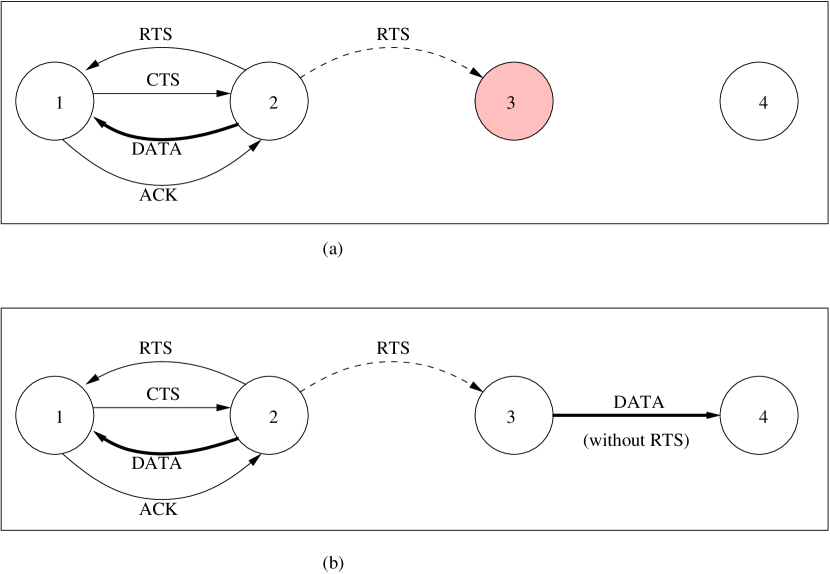
Exposed node problem, on the other hand, occurs because of a misdirected carrier sense which results in refraining from data transmission even in the situations where collisions would not occur causing a reduced overall channel utilization. To the best of our knowledge, there exists no practical solution to this problem. Further the collision avoidance mechanism, if used, results in a conservative behavior by all the nodes that are present in the vicinity of the nodes that are currently using the wireless channel. In this work, we propose a mechanism called the Intelligent Collision Avoidance (ICA) which tries to improve the channel utilization by allowing the exposed nodes to carry on data transmissions in parallel whenever possible. This mechanism leverages on the RTS/CTS messages exchanged during the collision avoidance phase to deduce the directionality of transmission and RTS/CTS threshold values to carry out parallel data transmissions.
6.1 Proposed Scheme
The root cause of exposed node problem is the misdirected carrier sense by nodes causing unwarranted refraining from data transmissions. In the pure CSMA MAC, it becomes impossible to deduce the location of intended receivers of any data transmission. But in CSMA/CA protocols it is possible to decipher the directionality of the data transmissions by leveraging on the control messages exchanged during the collision avoidance phase. We assume that the wireless transmission characteristics are symmetric, i.e. the mutual signal levels that are observed at any two nodes are same provided the transmission power used by both the nodes is same.
In our scheme we intend to rely on the signal strength of the CTS message that is sent by the receiver node to decipher the directionality of data transmissions and hence asses the impact of any parallel data transmission on the reception of receiver node. In basic CSMA/CA protocol whenever a node hears an RTS message it refrains from transmitting any data. But instead it can rely on the absence of CTS response to decipher that the receiver happens to be out of range for transmissions from this node and hence it is an exposed node for this particular instance of transmission. In such case the exposed node can initiate a parallel data transmission improving the channel utilization. In Figure 15 node 3 is the exposed node, node 1 is the receiver, and node 2 is the sender.
Although the exposed node can safely transmit data, it can not receive any data because of other ongoing data transmission. Thus the exposed node is accompanied by a hidden node which has already initiated data transfer. In Figure 15 node 3 is the exposed node and node 2 is the hidden node for node 4. Thus, any transmission by node 4 intended for node 3 will not be heard by it because of ongoing transmission from node 2. This would hamper tranmissions like CTS from node 4. This forces node 3 to resort to data transmission without using collision avoidance. Further, if the MAC protocol uses link level ACKs then the exposed node can turn into a hidden node for the ACK traffic. This problem can be resolved by limiting the data transmission by the exposed node so that the ACK is not garbled. This requires a proper estimation of the data transmission time and the time at which the ACK will be transmitted.
The timing estimate can be easily obtained from the RTS frame that is initially transmitted by the sender node. The exposed node can now limit the data transmission for this duration. The limiting size can be determined by using the existing fragmentation logic in the MAC.
The medium access algorithm for every node intending to transmit data in this case is:
-
•
Sense the channel for the DIFS period
-
•
If an RTS message is seen, wait for CTS timeout, else follow the usual DCF procedure.
-
•
In the absence of CTS message, deduce that the node is an exposed node and start data transmission. Fragment the data so that the data transfer ends exactly when the data transmission from the node sending RTS also ends.
-
•
Wait for ACK. If an ACK is not received assume that the data did not get transmitted properly else follow the same procedure for remaining portion of data.
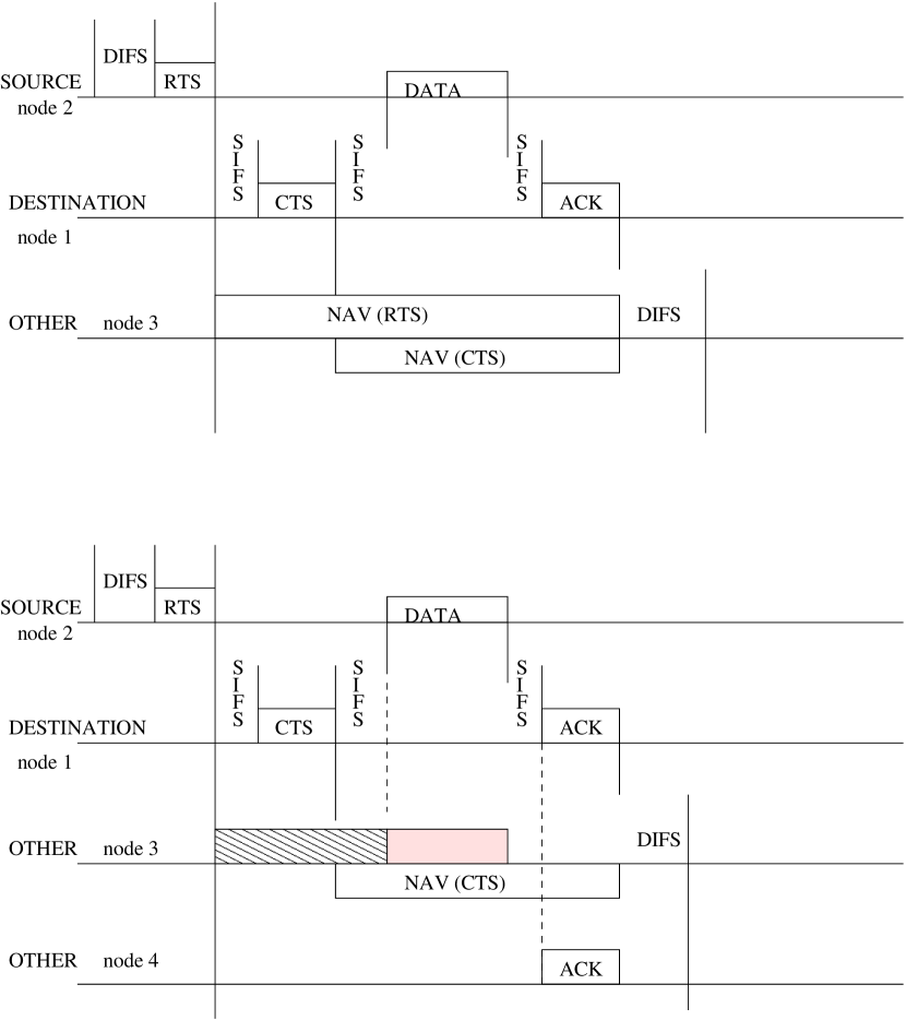
The resulting timing diagram is depicted in Figure 16.
6.2 Performance Simulation
We are in the process of analyzing this modification to protocol. We have modified the NS-2 simulator with an extension for ICA. We have observed a two-fold performance gains for simple string topology. We plan to evaluate our scheme for the following aspects:
-
•
Scalability: The extent to which parallel data transmissions are possible. How different topologies and different number of nodes involved affect our scheme.
-
•
Range: One of issues here is the impact of ratio of hearing range and sense range. If the sense range of wireless NICs is much higher than the hearing range then it is not clear how parallel transmissions are going to affect each other. We are relying on the radio capture effect to decipher packet transmissions correctly in the event parallel transmissions interfere with each other.
-
•
Mobility: The impact of mobility is unclear. We are relying on long coherence period to alleviate the impact of mobility on the overall scheme.
-
•
Power consumption: The Intelligent Collision Avoidance scheme promises throughput gains at an expense of additional power. We intend to analyze the exact impact of the schema on the overall power consumption in the network.
7 Conclusions
Though IEEE 802.11b is the most dominant wireless LAN technology today, it is evident that is not a well matured technology and has a fair share of its own problems.
In this survey we focused on certain aspects of 802.11b like performance issues, QoS, and fairness. We highlighted the main issues in these areas and compared the current research aimed at performance enhancement, QoS provisioning, and fair scheduling. Most of the solutions we reviewed are closely related to the MAC layer enhancements. It is possible to solve all these solution by enhancing/modifying different aspects of the protocol stack. As an example we cite various TCP performance related solutions at different levels. It is our observation that the solutions are effective and simple if these are provided at the source of the problem itself. The basic distinguishing factor for wireless media from wired media is the nature of the medium itself. Thus, it is our belief that most of the solutions for the problems introduced because of quirkiness of wireless medium should be provided closest to the medium and that is the MAC layer of the protocol stack.
We also suggested a scheme (ICA) to improve the overall network throughput by slight enhancements to the MAC layer. ICA is inspired by other MAC layer schemes like RBAR, OAR, and MACAW protocol. In future, we plan to evaluate ICA to verify its effectiveness. We also plan to study various scalability, mobility, and other related issues.
References
- [1] IEEE. “IEEE Standard for Wireless LAN Medium Access Control (MAC) and Physical Layer (PHY) specifications”. Institute of Electrical and Electronics Engineers, November 1999.
- [2] Gartner group. http://www.gartner.com.
- [3] P. Karn. “MACA - A New Channel Access Method for Packet Radio”. In Proceedings of 9th ARRL Computer Networking Conference, 1990.
- [4] L. Zhang, S. Berson, S. Herzog, and S. Jamin. “Resource ReSerVation Protocol (RSVP)”. IETF RFC 2205, Sep 1997.
- [5] W. Feng, K. Kandlur, D. Saha, and K. Shin. Adaptive packet marking for providing differentiated services on the Internet. In Intl. Conf. on Network Protocols, Oct 1998.
- [6] P. Almquist. Type of Service in the Internet Protocol Suite. RFC 1349, Jul 1992.
- [7] Srikant Sharma, Kartik Gopalan, Ningning Zhu, Pradipta De, Gang Peng, and Tzi cker Chiueh. “Implementation Experiences of Bandwidth Guarantee on a Wireless LAN”. In ACM/SPIE Multimedia Computing and Networking (MMCN 2002), January 2002.
- [8] S. Mangold, S. Choi, P. May, O. Klein, G. Hiertz, L. Stibor. “IEEE 802.11e Wireless LAN for Quality of Service”. In Proceedings of the European Wireless, volume 1, pages 32–39, Florence, Italy, February 2002.
- [9] Sai shankar and Sunghyun Choi. “QoS Siganling for Parameterized Traffic in IEEE 802.11e Wireless LANs”. In AISA 2002, pages 67–84, 2002.
- [10] Peter Johanson. “Hybrid Coordinator Simplifications: Queue State element and Express traffic”. IEEE 802.11-01/597r0, November 2002.
- [11] V. Bharghavan, A. Demers, S. Shenker, and L. Zhang. “MACAW: A Media-Access Protocol for Packet Radio”. In Proceedings of ACM SIGCOMM, 1994.
- [12] Can Emre Koksal, Hisham Kassab, and Hari Balakrishnan. An analysis of short-term fairness in wireless media access protocols (poster). In Measurement and Modeling of Computer Systems, pages 118–119, 2000.
- [13] Zoran Hadzi-Velkov and Boris Spasenovski. “Capture Effect in IEEE 802.11 Basic Service Area Under Influence of Rayleigh Fading and Near/Far Effect”. In The 13th IEEE International Symposium on Personal, Indoor and Mobile Communications, 2002.
- [14] Shugong Xu and Tarek Saadawi. “Does the IEEE 802.11 MAC Protocol Work Well in Multihop Wireless Ad Hoc networks?”. IEEE Communications Magazine, pages 130–137, June 2001.
- [15] Zuyuan Fang, Brahim Bensaou, and Yu Wang. “Performance evaluation of a fair backoff algorithm for IEEE 802.11 DFWMAC”. In Mobile Computing and Networking, pages 48–57, 2002.
- [16] V. Kanodia, C. Li, A. Sabharwal, B. Sandeghi, and E. Knightly. “Ordered Packet Scheduling in Wireless Ad Hoc Networks: Mechanisms and Performance Analysis”. In ACM MOBIHOC’02, September 2002.
- [17] Nitin H. Vaidya, Paramvir Bahl, and Seema Gupta. Distributed fair scheduling in a wireless LAN. In Mobile Computing and Networking, pages 167–178, 2000.
- [18] S. J. Golestani. “A Self-Clocked Fair Queueing Scheme for Broadband Applications”. In IEEE INFOCOM’94, 1994.
- [19] J. Walrand and P. Varaiya. “High-Performance Communication Networks”. Morgan Kaufman, 2nd edition, 2000.
- [20] George Xylomenos and George C. Polyzos. “TCP Performance Issues over Wireless Links”. IEEE Communications Magazine, pages 52–58, April 2001.
- [21] G. T. Nguyen, Randy H. Katz, Brian Noble, and Mahadev Satyanarayanan. “A Trace-Based Approach for Modeling Wireless Channel Behavior”. In Proceedings of Winter Simulation Conference, pages 597–604, December 1996.
- [22] A. Bakre and B. R. Badrinath. “A Comparision of Mechanisms for Improving TCP performance over Wireless Links”. In Proceedings of the second USENIX Symposium on Mobile and Location Independent Computing, April 1995.
- [23] Hari Balakrishnan, Srinivasan Seshan, and Randy H. Katz. “Improving Reliable Transport and Handoff Performance in Cellular wireless Networks”. ACM Wireless Networks, 1995.
- [24] George Xylomenos and George C. Polyzos. “TCP and UDP Performance Over a Wireless LAN”. In Proceedings of the IEEE INFOCOM‘99, pages 439–446, March 1999.
- [25] Haitao Wu, Yong Peng, Keping Long, Shiduan Cheng, and Jian Ma. “Performance of Reliable Transport Protocol over IEEE 802.11 Wireless LAN: Analysis and Enhancement”. In Proceedings of the IEEE INFOCOM‘02, June 2002.
- [26] Ad Kameraman and Leo Monteban. “WaveLAN-II: A High-Performance Wireless LAN for the Unlicensed Band”. Bell Labs Technical Journal, pages 118–133, Summer 1997.
- [27] Gavin Holland, Nitin Vaidya, and Paramvir Bahl. “A Rate-Adaptive MAC Protocol for Multi-Hop Wireless Networks”. In ACM MOBICOM’01, july 2001.
- [28] B. Sandeghi, V. Kanodia, A. Sabharwal, and E. Knightly. “Opportunistic Media Access for Multirate A Hoc Networks”. In ACM MOBICOM’02, September 2002.
- [29] Lars-Ake Larzon, Mikael Degermark, and Stephen Pink. “UDP Lite for Real Time Multimedia Applications”. In Proceedings of the Sixth IEEE International Workshop on Mobile Multimedia Communications, 1999.
- [30] Ashish Raniwala and Tzi-cker Chiueh. “Transient Ad Hoc Networks for IEEE 802.11b”. http://www.cs.sunysb.edu/ raniwala/microAdhoc, 2003.
- [31] N. Abramson. “The ALOHA system - Another Alternative for Computer Communications”. In Fall Joint Computer Conference, AFIPS Conference, 1970.