Programmable Ethernet Switches and Their Applications
Abstract
Modern Ethernet switches support many advanced features beyond route learning and packet forwarding such as VLAN tagging, IGMP snooping, rate limiting, and status monitoring, which can be controlled through a programmatic interface. Traditionally, these features are mostly used to statically configure a network. This paper proposes to apply them as dynamic control mechanisms to maximize physical network link resources, to minimize failure recovery time, to enforce QoS requirements, and to support link-layer multicast without broadcasting. With these advanced programmable control mechanisms, standard Ethernet switches can be used as effective building blocks for metropolitan-area Ethernet networks (MEN), storage-area networks (SAN), and computation cluster interconnects. We demonstrate the usefulness of this new level of control over Ethernet switches with a MEN architecture that features multi-fold throughput gains and sub-second failure recovery time.
Keywords: System design, Simulations, Experimentation with real networks/Testbeds, Ethernet, Spanning Tree.
I Introduction
Ethernet technology has come a long way from its initial shared-media 10 Mbps capability to today’s switched-media form providing throughput up to several Gbps. Its simplicity, cost effectiveness, and the economies of scale have enabled it to make forays into practically various scales of networks, including metropolitan area networks. Recent technological advances, such as Ethernet in the First Mile [1], which enables subscribers to connect to an Ethernet-based core network over a wide variety of media ranging from voice grade copper to multi-mode fiber, further reinforce the case of metropolitan Ethernet network (MEN) architecture. Bandwidth availability of up to 10 Gbps and micro-second level message latencies also make Ethernet a low-cost alternative to widely used cluster interconnects (CI) such as Myrinet [2], Quadrics [3], and Infiniband [4]. Finally, with the increasing momentum of IP storage, Ethernet-based storage area networks (SAN) are becoming formidable challengers against fiber channel-based SAN because of lower cost and additional flexibility. These new applications of Ethernet elevate it from a LAN technology to a ubiquitous networking technology.
Many Metro Ethernet services today are actually built on circuit switched technologies such as SONET, ATM, RPR, or established packet switching technologies like MPLS etc. These services are actually provided by means of tunnels set up over these physical carrier technologies. Deployment of standard Ethernet switches in the core is still very rare, because there are several architectural deficiencies with switching in Ethernet. First, Ethernet networks use a spanning tree protocol (IEEE 802.1d) [5] to establish a path between any pair of nodes. It is well known that the spanning tree approach fails to exploit all the physical network resource. In addition, failure of switches and links requires rebuilding the of spanning tree, which is a lengthy process. IEEE 802.1w [6], the rapid spanning tree configuration protocol (RSTP), mitigates this problem by providing mechanisms to detect failures and quickly reconfigure the spanning tree. However, the recovery period can still range from an optimistic 10 milliseconds to more realistic multiple seconds after failure detection, which is still not adequate for many applications. Second, Ethernet does not support any mechanism akin to MPLS [7], which allows the user to route packets/flows along a particular path. As a result, it is impossible to apply any traffic engineering technique [8] to balance traffic load across the network. Traffic engineering may not be useful in small local area networks, but is very important in the context of MAN, SAN, and CI. In particular, the ability to route traffic on a given route can also greatly help enforcing QoS by leveraging the traffic prioritization scheme (IEEE 802.1p) [9], which prioritizes certain classes of traffic over others.
The key insight of this work is that modern Ethernet switches incorporate advanced network control mechanisms that are programmatically configurable and could be used to improve the aggregate throughput, the availability and the QoS. Virtual LAN (VLAN) [10] technology provides a mechanism to a physical subnet into multiple broadcast domains to improve the security and performance of LANs. Multiple spanning tree (MST) protocol [11] makes it possible to configure multiple spanning tree instances on a network, each associated with a distinct VLAN, to isolate traffic from one another. Many commercially available Ethernet switches also support IGMP snooping [12] for making intelligent multicast forwarding decision by examining the Layer-3 IP headers and use the network resources more efficiently. Finally, most Ethernet switches can limit the rate of incoming or outgoing packets over their physical interfaces.
Most of these advanced structuring mechanisms in modern Ethernet switches are accessible through SNMP, HTTP, or command line interface. It is possible to remotely configure VLANs and their associated spanning trees, IGMP snooping and interface rate limits using management protocols. It is also possible to remotely monitor switches for failures and different activities can be triggered in reaction to these failure events. These features are thus referred to as programmable features of modern Ethernet switches.
In this paper, we show that the programmable control mechanisms of modern Ethernet switches can be used to build the following high-level functionalities that are critical to MEN, SAN, and CI applications – (i) Enable traffic engineering that in turn routes packet traffic to balance the load of physical network links. Routes obtained from switching path selection are enforced by means of VLAN tags in a fashion similar to MPLS labels. (ii) Enable proactive switch and link disjoint backup path provisioning to provide a very high degree of tolerance of switch or link failures. (iii) Use rate limiting features of Ethernet switches to regulate the bandwidth consumption of end nodes in order to isolate different traffic from one another. (iv) Use IGMP snooping and link-layer multicast to support link-layer multicasting without broadcasting.

II Switching Path Selection
In Ethernet, packets are always switched along the spanning tree of the network. The sender nodes***Throughout this paper, we use the terms nodes and hosts to refer to the end-hosts that are connected to a switched networks. The switch-nodes of the network are always explicitly referred as switches in the paper. do not have any control over the switching path. In large scale networks like MAN, the number of network elements (links and switches) involved in a path between far off end-hosts is usually high. Failure of any of these elements can cause a complete communication breakdown between the given pair of end-hosts. Further, the intermediate links are shared by multiple switching paths. This sharing may lead to an overload situation and the absence of alternate switching paths precludes any scope of load balancing by offloading traffic to other links. Figure 1 depicts a typical load imbalance scenario when switching is done along a spanning tree.
Storage and cluster networks primarily require high switching bandwidth and low communication latency between different nodes. In switched Ethernet, the peak bandwidth between any two segments is limited by the bandwidth of the link connecting them. Addition of multiple links does not improve the situation because, in spanning tree topology, there can be only one active link forwarding traffic to a segment. Thus, the general tendency is to aggregate the cluster nodes on a single switch with high port density. The aggregation cost of switching networks increases rapidly with the size of the cluster which in turn raises the per port cost factor.
| Let the set of all load balanced paths be | ||
| Let the set of all edge pairs be | ||
| Let the set of spanning trees be | ||
| Let = | ||
| Sort the members of in the descending order of path | ||
| length | ||
| While ( and ) | ||
| Sort the members of in descending order of their | ||
| frequency of appearance in members of | ||
| Let = Next element in | ||
| While such that | ||
| Remove from | ||
| Find such that and do not form a loop | ||
| Merge with | ||
| If no such is found, add to |
II-A VLAN-based switching
IEEE 802.1s MST protocol allows for the existence of multiple spanning trees in an Ethernet network, where each spanning tree corresponds to different VLANs. These multiple spanning trees can be used to provide load balanced and fault-tolerant switching paths for different communicating nodes. Given the traffic profile or traffic requirements of any network, one can come up with different load balanced switching paths such that the overall network utilization is efficient [13]. These load balanced switching paths can be aggregated together such that there are no loops in the aggregation. Such a constrained aggregation would yield multiple spanning trees. Each spanning tree can further be associated with a unique VLAN tag. The details of deriving load balanced switching paths and grouping them into multiple spanning trees are discussed in [14]. The path aggregation algorithm is shown in Figure 2 for quick reference. This algorithm tries to minimize the overall number of spanning trees and hence VLANs required after aggregation. Since the number of overall spanning trees required is inversely proportional to the number of paths grouped together, the number of spanning trees can be reduced by including larger number of paths together. To increase the number of paths per spanning tree, the algorithm tries to merge paths which share common features such as sub paths, edges, or simply nodes. The end result would be that each load balanced path is part of a spanning tree which is identified by a unique VLAN tag.
For every incoming packet, the switches analyze the Ethernet header for VLAN tags. If a VLAN tag is found, the packet is switched along the corresponding spanning tree. Thus, any specific switching path can be selected by simply inserting the appropriate VLAN tag in the packet header. A host can insert different VLAN tags while communicating with different destination nodes and thus can select different load balanced switching paths. This mechanism is very much analogous to MPLS, where the packet switching paths are selected based on the labels present in packet headers. The difference is that, in MPLS, the labels are inserted by ingress routers, whereas here the VLAN tags need to be inserted by the end hosts.
This VLAN-based switching is feasible only if a desired VLAN spanning tree can be imposed (configured) on any network. This is where the programmability features of Ethernet switches come into picture. Almost all switches, which provide support for 802.1s MST protocol, also facilitate programmability of links in terms of associated VLANs. Usually, whenever VLANs are associated with different switches (links) in a switched network, the switches participate in a distributed spanning tree setup process and build a packet forwarding spanning tree. However, if the links with which a particular VLAN is associated already form a spanning tree, this spanning tree becomes the default switching spanning tree for that VLAN. Thus, with the availability of VLAN programmability features in switches, it is possible to realize this programmable VLAN-based switching which enables efficient traffic engineering.

II-B Fault Tolerance
Most managed (programmable) switches provide status monitoring facilities where one can remotely setup traps which can get triggered by various events like, link failure, neighboring switch failure, link recovery, switch recovery, neighbor discovery, etc. Using these traps one can detect topology changes and failures in the network. If for every communicating host-pair, a backup path is provisioned, it is easy to deal with failure scenario by simply switching the communication over to the VLAN that corresponds to the backup path. In order to deal with failure of any switch or link in the communication path, the backup path must be a link and switch disjoint path to the primary path. Due to the disjoint nature, the primary and backup paths belong to different spanning trees (and hence different VLANs). Failures in one spanning tree do not affect other spanning trees which do not include the failed links. Since the primary and backup paths are pre-provisioned through traffic engineering, the fail-over duration is limited to failure detection and event communication latencies between switch and the status monitoring nodes. The failure detection latencies for commercially available managed switches such as Cisco Catalyst 2924 range from 400 to 500 milliseconds. The fail-over period observed in this case does not exceed 500 to 600 milliseconds and is consistently in the sub-second range. This is a significant improvement over multiple second fail-over latency of 802.1w RSTP deployment. Note that, 802.1w failure recovery period does not take into account the failure detection period and is just the convergence period for spanning tree recovery.
One caveat about the above mentioned detection and recovery mechanism is that it needs the presence of status monitoring node(s) in the network which is(are) aware of the entire network topology and the traffic provisioning therein. Further, it is essential that the status monitoring node is always reachable from all the switched in the network and all nodes which need to be notified about the failure and the new VLAN tags that need to be used. If a network failure disrupts the communication path between the failure detecting switch and the monitoring node itself, the fail-over mechanism cannot proceed. However, this situation can be overcome by dispatching the failure notification over multiple communication paths to the status monitoring node. Another possibility is to have multiple status monitoring nodes strategically located in the network such that at least one status monitoring node can communicate with the failure detecting switch and all the affected nodes. An example failure recovery scenario is depicted in Figure 3.
III Efficient Reliable Multicast
Nodes in any high end cluster interconnect need to communicate with each other for exchanging data as well as perform state checkpointing and message logging for fault tolerance. It is often the case that the same data is transmitted to multiple nodes during checkpointing and message logging. For example, the cluster nodes may exchange periodic heartbeat messages with several other nodes monitoring the health of the entire cluster. The state checkpointing data may be replicated across multiple nodes for an increased level of fault tolerance. In storage area networks, data is usually mirrored over multiple storage nodes. In all these cases, the network performance can be significantly improved if such communication is done over a multicast protocol rather than unicast protocol. Traditionally, link-layer multicast over Ethernet networks was implemented through coarse broadcast-and-filter semantics. The Ethernet switches treated link-layer multicast packets as broadcast packets and the transmission was done over all the switch port. The onus of filtering out irrelevant broadcast packets on the basis of destination MAC addresses was placed on the end-host network interface cards (NICs). Though this mechanism relieved end-host CPUs from redundant packet processing burden, the network performance suffered significantly because of unnecessary packet forwarding to all the ports.
Fortunately, most modern Ethernet switches, particularly Gigabit switches, support a feature called IGMP snooping, which was designed to support IP multicast without using link-layer broadcasting. In the IP multicast schema, a node can join or leave a multicast group by sending a join or leave IGMP [15] packets to the designated routers which take care of propagating these messages to upstream routers. In order to avoid redundantly broadcasting the downstream multicast traffic, Ethernet switches monitor these IGMP join and leave messages to determine the ports on which the multicast traffic needs to be forwarded. Subsequently, all downstream multicast traffic is forwarded to only specific ports.
Although IGMP snooping was designed to improve the efficiency of IP multicast on switched Ethernet networks, it can be exploited to support link-layer multicast as well. Whenever a multicast group rooted at a particular node needs to be created, the only thing the participating nodes need to do is to send an IGMP join message to the root node. The intermediate switches would monitor the IGMP messages and construct a spanning tree connecting the participating ports. Once such a spanning tree is established, all multicast packets are forwarded along the spanning tree rather than link-layer broadcasting. If different such spanning trees, catering to different multicast groups, are pre-configured through traffic engineering for efficient network performance, all these trees can be aggregated together in a way similar to path aggregation described in Figure 2. This aggregation would yield system-wide spanning trees. These spanning trees can then be constructed in the network by using the programmable features mentioned earlier.
The reliability of the link-layer multicast can be ensured by implementing a positive acknowledgment and timeout based scheme. In this scheme, after every multicast transmission, the sender sets a timer and expects every receiver in the group to return an acknowledgment before the timer expires. If some receivers fail to acknowledge the reception in time, the sender can resort to unicast transmission to each such receiver. This scheme is simple and efficient, and is optimized for the case when packet drops and corruptions are extremely rare, as in the case of switched Ethernet networks.
The number of link-layer multicast groups a switch can support is limited. Typically, the commodity switches can support up to 500 multicast groups. To perform traffic engineering based on the communication profile of all the nodes and to limit the number of per-switch multicast groups are some of the key challenges in multicast provisioning. These problem can be addressed by maximizing the number of nodes that can share a multicast tree without affecting the overall performance and then performing traffic engineering. There can be various ways the traffic engineering can be performed. One of the plausible ways is to use the hose model [16] developed for resource management in VPNs. Though this model is challenging to support from traffic provisioning aspect, it captures the essence of multicast traffic in the sense that the traffic profile specification is in the form of the amount traffic moving in and out of the nodes rather than pairwise statistics as required by the traditional pipe models.
IV QoS Enforcement
Traffic engineering and bandwidth provisioning alone cannot provide quality of service in a network. It requires network usage policing and regulation to provide a desired degree of QoS in the network. Without usage regulation, the best one can do is to provide QoS on the lines of priority based DiffServ [17] in the Internet. This kind of mechanism is inadequate to insulate different traffic flows from one another and is not an acceptable scenario in MAN where adherence to service level agreement (SLA) is a very crucial requirement. Ethernet also specifies a DiffServ like traffic class prioritization mechanism [9] which is supported by almost all Ethernet switches. But it is clearly inadequate because of lack of global enforcement.
The key to regulate the network usage and insulate different traffic flows from one another is to monitor and enforce the usage right at the ingress points in the network. If the amount of inflow network traffic does not exceed the total engineered traffic, different traffic flows cannot affect each other unless some of the network elements have failed. If the traffic engineering is performed with proper backup provisioning, it can be ensured that all the traffic flows are insulated from each other even after failures.
Many mid-end and high-end Gigabit Ethernet switches support programmable rate limiting features. For efficient wire speed, these features are usually implemented in hardware. Rate limiting can be used to provide restricted bandwidth usage based on predefined profile or per physical port usage. Excess traffic can either be dropped or reprioritized. Though typically supported programmable parameters of rate limiting are quite extensive, it can be simply specified in terms of the raw bandwidth limitations and the burst size limits. Using these rate limiting features, it is possible to regulate the inflowing traffic at the ingress ports. The amount of allowed inflow traffic can be determined from the SLA in metro network scenario or from the traffic characterization in the cluster interconnect scenario. Further, the 802.1p traffic classification and prioritization can be used to mark lower priority for the traffic that is sent in excess of the allowed traffic so that this traffic is serviced only if there is spare bandwidth available on every link and every switch along the path.
V Programmability Requirements
To realize the programmable switching Ethernet paradigm there are certain minimum features that should be supported by the switches in the network. The most important feature is the 802.1q tag based VLAN support with 802.1s MST support. This feature needs to be supported by all the switches in the network. Similarly, all switches also need to support link and switch status monitoring capability for fault tolerance. Further, for a robust fault tolerance mechanism, the status monitoring node needs to be able to communicate with all the switches even after multiple failure. This can be achieved by sending multiple failure notification over different paths. Another alternative can be to place multiple status monitors at strategic locations in the network.
The rate limiting feature is required to regulate the inflow of traffic from end-hosts. It is worth exploring, whether all switches in the network need to support this feature. Rate limiting is essential only when an end-host is connected to a switch. In MAN setup, the switches can be classified as core switches and edge switches where the edge switches serve as ingress points. The core switches need not participate in the rate limiting activity as the edge switches ensure that the traffic reaching core switches is already rate limited. This mechanism is analogous to ingress filtering in Internet. An alternate viewpoint can be that, usually there is spare bandwidth available at the edges but the core of the network carries most of the traffic, so it should be the core where bandwidth regulation takes place rather than at the edges. This argument also has some merit in it. However, the final decision can be made only after traffic engineering. But unfortunately, traffic engineering requires the knowledge of topology which usually gets acquired after deployment. Moreover, when bandwidth provisioning is done based on customer requirements and SLAs, service providers prefer to use statistical multiplexing to maximize the network utilization. The rate limiting feature cannot deal with congestion occurring because of inherent inability of statistical multiplexing to deal with worst case scenario.
In cluster and storage networks, potentially all switches may support end-hosts. This makes it essential to support rate limiting at all the switches. Also, the traffic profile may change from time to time. Strict rate limiting on a changing traffic profile fails to capture the changing requirement and hence is inappropriate. The proper way to tackle this is to adapt soft rate filtering with re-prioritization of excess traffic so that no traffic is dropped as long as there is network capacity available to service it. In addition, if the current traffic profile differs significantly from the profile used for bandwidth provisioning, traffic re-engineering needs to be carried out
Throughout the discussion, we implicitly assumed the availability of traffic monitoring and engineering mechanism. Traditional pipe model based traffic engineering requires pairwise load statistics for all end-hosts. Even if traffic specifications is provided by customers, as in MAN case, precise traffic profiling is required to exploit statistical multiplexing. Commodity Ethernet switches maintain statistics such that the amount of traffic entering and leaving the ports and some other finer details such as traffic per VLAN, amount of multicast traffic, etc. This is clearly insufficient to build a complete pairwise traffic profile. There are two possible solutions to this problem. The traffic engineering can use the hose model [16] of resource management. This model provides the flexibility of traffic specification in terms of required input and output capacities at the end-hosts rather than a pairwise traffic matrix. However, resource provisioning becomes a tougher problem to solve in this context. An alternative is to modify the end-hosts to keep track of pairwise traffic between all peers. These end-hosts can then periodically communicate these statistics to the nodes responsible for traffic engineering. This approach is feasible in storage and cluster networks where all the nodes fall under a common administrative domain.
Whenever end-hosts need to communicate with other peers, the switching path is selected by specifying the VLAN corresponding the spanning tree along which the packets are switched. The sending node needs to insert the appropriate VLAN tag in the packet header. This tag needs to be obtained from some node aware of traffic engineering. Further, during fail-over, the status monitors inform the sender nodes to change over to backup VLANs. This requires all senders to be aware of the path-selection and fail-over mechanism in order to comply with and utilize them. It may not be possible to modify the network stack of customer nodes in environments like MAN. In such cases, the service provider can address this problem by placing proxy nodes which take care of interacting with service provider nodes.
VI Performance Benefits
We studied the improvement in aggregate through of a VLAN-based multi-spanning-tree Ethernet architecture over its single spanning tree counterpart using simulations. The simulations were carried out to determine the maximum bandwidth that could be supported in the network. The network topology was assumed to be a grid topology which can represent metro Ethernets and cluster networks. The simulations were carried out against a uniform traffic pattern of each node communicating with other nodes with equal traffic load. The uniform traffic distribution is a representation of cluster networks. The simulations were run against grids of sizes 16, 25, 36, 49, and 64 nodes connected using links with a capacity of 100 Mbps. The traffic between nodes was 10, 8, 5, 2, and 1 Mbps for grids of sizes 16, 25, 36, 49, and 64 respectively. The effectiveness of path selection was compared for possible throughput against the single spanning tree case. The path selection was carried out for both cases, with and without backup redundancy. All traffic comprised of at least one hop between the switches.
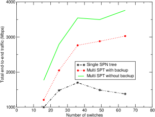
Figure 4 shows the comparative maximum throughput for single spanning tree network against the VLAN-based switching path selection. The traffic pattern is assumed to have a uniform distribution across all node pairs. This is a representative distribution of cluster networks. It can be seen that the total aggregate end-to-end throughput is always more in system. As the number of nodes increases the performance shows considerable increase. This is because of availability of additional number of active links in topology.
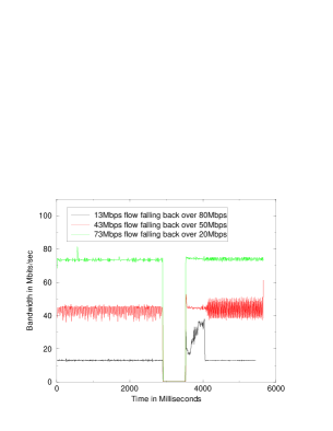
Figure 5 shows the effect of link failure on TCP throughput. The experiment was run with a setup where two switches were connected by two links. These links were then configured to belong to two different VLANs. To have a more realistic scenario, we introduced enough background traffic to keep the link utilization at the maximum level in the VLAN that served the main traffic. Upon link failures, the TCP traffic passing through this link falls back onto the backup VLAN, which happens to pass through the other link. There was an expected drop of bandwidth for the recovery period (around 600 milliseconds) Once the backup VLAN was used, the TCP flow regained its momentum hardly suffering any more delay and attaining stability in around 300ms to 400ms. Thus, the complete failure recovery time can be broken down into following components: The failure detection time, including the event notification to status monitor, of around 400 to 600 milliseconds and the VLAN change notification time of a few milliseconds. The total down-time incurred is in sub-second range.
VII Conclusion
Lack of fine-grained path selection mechanism in Ethernet networks is a major barrier for the application of traffic engineering technology. The fallout of this restriction has been a limiting factor for Ethernet deployment in the core carrier networks. Though Ethernet is becoming more and more popular, this popularity is from access perspective and not from the core network perspective. In this paper, we described how the programmable control mechanisms in modern Ethernet switches support MPLS-like load-balancing path selection to provide multi-fold network throughput gains. When combined with status monitoring in Ethernet, this fine-grained path selection can be used to provide sub-second level fault tolerance, which is a required feature in core networks. We also described a simple efficient reliable multicast protocol which uses Layer-3 awareness of commercially Ethernet switches to improve the performance of storage and cluster networks. We believe there are many more high-level functionalities that can be composed from the basic programmable control mechanisms. One of the future directions for this work is to explore and build interesting high-level functionalities that can enhance large scale networks as a whole.
References
- [1] IEEE, “IEEE Standard for Local and Metropolitan Area Networks: Ethernet in the First Mile,” Institute of Electrical and Electronics Engineers, 2004.
- [2] Nanette J. Boden, Danny Cohen, Robert E. Felderman, Alan E. Kulawik, Charles L. Seitz, Jakov N. Seizovic, and Wen-King Su, “Myrinet: A Gigabit-per-Second Local Area Network,” IEEE Micro, vol. 15, no. 1, pp. 29–36, 1995.
- [3] F. Petrini, W. Feng, A. Hoisie, S. Coll, and E. Frachtenberg, “The Quadrics NetworkL High-Performance Clustering Technology,” IEEE Micro, vol. 22, no. 1, pp. 46–57, 2002.
- [4] “Infiniband Specification,” Infiniband Trade Association, Jun 2001.
- [5] IEEE, “IEEE Standard for Local and Metropolitan Area Networks: Media Access Control (MAC) Bridges,” Institute of Electrical and Electronics Engineers, 1990.
- [6] IEEE, “IEEE Standard for Local and Metropolitan Area Networks: Rapid Configuration of Spanning Tree,” Institute of Electrical and Electronics Engineers, 2000.
- [7] E. Rosen, A. Viswanathan, and R. Callon, “Multiprotocol Label Switching Architecture,” IETF RFC 3031, Jan 2001.
- [8] G. Ash, “Traffic Engineering & QoS Methods for IP-, ATM-, & TDM-Based Multiservice Networks,” Internet Draft, Oct 2001.
- [9] IEEE, “IEEE Standard for Local and Metropolitan Area Networks: Supplement to Media Access Control (MAC) Bridges: Traffic Class Expediting and Multicast Filtering,” Institute of Electrical and Electronics Engineers, 1998.
- [10] IEEE, “IEEE Standard for Local and Metropolitan Area Networks: Virtual Bridged Local Area Networks,” Institute of Electrical and Electronics Engineers, 1998.
- [11] IEEE, “IEEE Standard for Local and Metropolitan Area Networks: Multiple Spanning Trees,” Institute of Electrical and Electronics Engineers, 2002.
- [12] “Understanding IGMP Snooping,” Dell PowerConnect Application Note 18.
- [13] K. Gopalan, “Efficient network resource allocation with QoS guarantees,” Technical Report TR-133, Experimental Computer Systems Labs, Department of Computer Science, State University of New York at Stony Brook, March 2003.
- [14] Srikant Sharma, Kartik Gopalan, Susanta Nanda, and Tzi cker Chiueh, “Viking: A Multi-Spanning-Tree Ethernet Architecture for Metropolitan Area and Cluster Networks,” in Proceedings of the IEEE INFOCOM‘04, Mar 2004.
- [15] W. Fenner, “Internet Group Management Protocol, Version 2,” IETF RFC 2236, Nov 1997.
- [16] N. G. Duffield, Pawan Goyal, Albert Greenberg, Partho Mishra, K. K. Ramakrishnan, and Jacobus E. van der Merive, “A flexible model for resource management in virtual private networks,” in ACM SIGCOMM, 1999, vol. 32 of 3, pp. 33–46.
- [17] S. Blake, D. Black, M. Carlson, E. Davies, Z. Wang, and W. Weiss, “An Architecture for Differentiated Service,” IETF RFC 2475, December 1998.