Equilibrium and Driven Vortex Phases in the Anomalous Peak Effect
In type-II superconductors, vortex lines are embedded in an atomic solid, and thus the low-temperature condensed vortex phase cannot exhibit true long-range translational order due to the random impurities in the atomic lattice [1]. Nevertheless when the random pinning is sufficiently weak, vortex lattice order can extend to very large distances. Upon increasing temperature or field, the vortex lattice will eventually transform into a disordered liquid [2-6]. In the search for the signature of a vortex solid-liquid transition in high- superconducting YBa2Cu3O7-δ (YBCO) crystals, with increasing temperature and in a strong magnetic field, two striking phenomena were discovered: a sharp peak in the critical current, i.e. a peak effect [7, 8, 9, 10], suggesting a sudden enhancement of vortex pinning; and, just above the peak effect, a sharp rise [11] of the ohmic resistance indicating a sudden increase in the vortex mobility. How these two effects relate to the microscopic processes by which a (quasi- [12]) ordered vortex lattice transforms into a disordered vortex liquid is still an unsettled issue.
The conventional interpretations of the peak effect are, in one form or the other, based on Pippard’s proposal of a static disordering of the vortex lattice in a random pinning potential[13, 14, 15]. The peak effect is a crossover from a regime where the vortex lattice is stiff to a regime where the vortex lattice becomes too soft to resist the random distortions due to the random pins. The suggested mechanisms [13, 14] for softening are of a purely electromagnetic origin. Since the discovery of the peak effect in high- superconducting YBCO crystals, the question arises as to whether there is a thermodynamic mechanism for the peak effect, and whether the peak effect is associated with the vortex solid-liquid transformation in the weak random pinning potential. For example, the peak effect in YBCO has been described as a result of [16, 17] or a precursor to [9] the melting of the vortex lattice. Specifically, it was argued by Tang et al. that within the Larkin-Ovchinnikov theory [14] of collective pinning, in which the typical pinning force density is determined by the shortest elastic length scale in the vortex lattice, a vortex-lattice melting can give rise to a pronounced peak effect, if the melting is more gradual than a one-step process [17]. The rise of the critical current at the onset of the peak effect is a crossover between two length scales: the Larkin pinning length and a short-range correlation length in the intermediate vortex phase(s) determined by thermal fluctuations, e.g. unbound dislocation loops [5], or other types of topological defects [18]. In this model, the peak effect and the subsequent resistive transition are different stages of the transition from a (quasi- [12]) ordered vortex-line lattice to a completely disordered vortex liquid. These intriguing possibilities give a strong motivation for the recent studies [19, 20, 21, 22, 23] of the peak effect in conventional type-II superconductors.
In this Letter, we describe an experiment which, for the first time, tests the predictions of the classical Pippard-type model and that of Tang et al. for the peak effect. For a given weak-pinning sample exhibiting a pronounced peak effect, the Tang model predicts that after the pinning has been artificially enhanced, the onset of the peak effect should move upward in field since the Larkin length is now reduced and the crossover should occur at a higher field deep within the intermediate vortex phase(s). The Pippard-type model gives exactly the opposite prediction: the onset of the peak effect should occur at a lower field. Our results are strongly in favor of the Tang model over the classical Pippard scenario of a static disordering for the peak effect. A detailed analysis of the data suggests that at least two types of topological defects, i.e. screw and edge dislocations, are responsible for disordering the vortex lattice and leading to a peak effect.
The experiments are performed on a 2H-NbSe2 crystal (“XV1-2” in [23], renamed as No.2) which was shown previously to exhibit a very pronounced peak effect, and which has a very low critical current density, demonstrating the weak-pinning nature of the starting sample [23]. The details of the experimental setup and calibrations are described previously [23]. Except for the data in Fig.3, all measurements are performed with the samples immersed in a liquid helium bath with temperature regulated at 4.20 K.
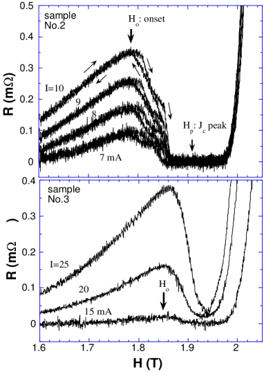
Fig.1 shows the main result of this paper. In the top panel, we plot the sample resistance as a function of the applied magnetic field of the virgin sample (No.2, dimensions 1.38mm (l) x 1.14mm (w) x 0.015mm (t) [24]) at low driving currents. The onset of the peak effect is defined as the point at which the sample resistance starts to decrease with increasing field. If one uses a voltage criterion to determine a critical current density , starts to rise with increasing field at about the same field value (see Fig.2, open circles). This sample (No.2) exhibits unusual features in the peak-effect regime. From to , the resistance is hysteretic upon field cycling. The resistance is higher for increasing field than for decreasing field. The difference in resistance between the two field cycles displays two striking peaks [23], suggesting (at least) two kinds of processes in the breakup of the vortex lattice. This is directly observable from Fig.1(top) in the peak-effect regime.
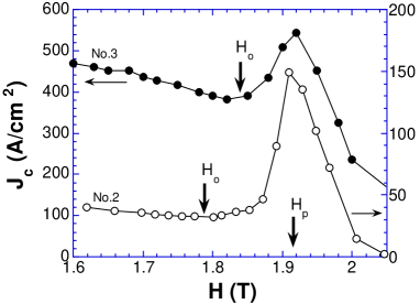
We find that, by mechanically bending or cutting the sample, one can add pinning centers to the sample and increase the critical current density, as shown in Fig.2. Sample No.3 (dimensions 1.38 x 0.25 x 0.015mm) was cut from the virgin crystal (No.2).
From Fig.2, one notices that the at 1.800 T is enhanced by a factor of 12.2, while the at 1.915 T (at the peak) is only increased by a factor of 3.5, from sample No.2 to sample No.3 after cold-working. This can be understood in the Larkin-Ovchinnikov theory if the vortex lines are pinned collectively below the onset of the peak effect, but individually at the apex of the peak effect. In the collective pinning regime, the Larkin-Ovchinnikov theory predicts that the pinning force density , where , , are density, force, and size of the pins, respectively. In the individual pinning regime, at the peak, . The enhancement factors can be understood if the density of pins in sample No.3 is 3.5 times greater than that of No.2. A factor of increase in is, therefore, expected in the low-field collective pinning regime. This analysis also explains why the peak effect is more pronounced in clean samples, since the ratio peak-/onset- increases with decreasing pin density. A transmission electron microscopy examination [25] of a similar cold-worked sample reveals large numbers of dislocations in the atomic lattice of the 2H-NbSe2 crystal, suggesting that these mechanically induced atomic-lattice defects are responsible for the enhanced pinning.
Thus the peak effect data in Fig.2 can be explained by the Larkin-Ovchinnikov theory if one assumes a crossover from a collective pinning regime below the peak effect to an individual pinning regime within the peak effect region. The underlying mechanism of this crossover, however, is the issue of current interest.
Larkin and Ovchinnikov suggested a mechanism [14] whereby this crossover occurs when the transverse Larkin length, , becomes smaller than the effective penetration depth , where is the London penetration depth, and . When this occurs, the nonlocality of becomes important and provides additional vortex-lattice softening. Thus Rc drops further and becomes softer still, leading to an elasticity “ultraviolet catastrophe.” Since , adding disorder () reduces , and the crossover should occur at a lower field. This is exactly the opposite of what we observe here. If Fig.2 is somewhat less convincing, Fig.1(lower panel) shows clearly that the onset of the peak effect in the cold-worked sample No.3 is higher than that of virgin sample No.2. In addition, the fine structures of the peak effect in the virgin sample are no longer observable. As shown in Fig.1(lower panel), in sample No.3, the resistance drop is essentially featureless and is no longer hysteretic in the peak-effect regime.
The disappearance of the fine features in the peak-effect regime and the upward shift in the onset field of the peak effect, however, are what one would expect if the onset of the peak effect in the virgin sample is an elastic instability driven by thermal fluctuations. In the Tang model [17], the onset of the peak effect is a crossover from the Larkin pinning length to a rapidly decreasing (with increasing or ) elastic length set by thermal fluctuations (although the random pinning may still play a role in the the elastic instability and the new elastic length). In the peak-effect regime, the vortex lattice behaves like a liquid at large length scales, but behaves like a solid at a short length scale. The long-wavelength liquid-like property of the pinned vortex lattice is cut off by the Larkin pinning length, and cannot manifest in the vortex transport until the liquid-like correlation length becomes smaller than the Larkin pinning length [17]. In this picture, by adding disorder () to a clean sample, the Larkin length, , becomes smaller, and the crossover occurs at a higher field, as is seen here. We thus propose that there is an equilibrium phase transition in the vortex lattice at the onset of the peak effect in the clean sample (No.2) where the resistance hysteresis begins. The pinned vortex lattice starts to break up spontaneously at this transition, but it takes two stages (each of which seems to be a first-order transition) for the vortex lattice to become completely disordered at the apex of the peak effect, both of which occur in a very narrow region of the diagram (see Fig.3 below). An apparently flowing vortex line fluid, characterized by an observable ohmic resistance, is achieved only at a larger (disorder-dependent) field, 2.05 T for sample No.2 and 2.40 T for sample No.5.
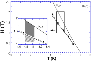
Here we should point out an early study of the effects of added pins on the peak effect in V3Si crystals [26]. Although it was not discussed, the vs. data showed that the onset of the peak effect shifted upward in field at low irradiation dosages. Further increases in irradiation shifted the onset to lower fields, leading to broad peaks as a function of magnetic field. Similar broad peaks were also found in high- superconductors, known as the “fish-tail” effect [27] or the “second-peak” effect [28]. However, if one plots the onset fields of these latter effects on the phase diagram, they are either temperature independent or have a positive slope [28]. Thus in those samples is a monotonic function of temperature. In Fig.3, we plot the temperature dependence of the onset of the peak effect on the phase diagram for sample No.3 (obtained using a variable temperature cryostat). A similar phase diagram was also measured using an ac-susceptibility technique [30]. Because its phase line has a negative slope on the diagram, the peak effect here can be observed as a function of temperature and magnetic field. Since the “fish-tail” [27] or the “second-peak” [28] effects are consistent with the nonlocality catastrophe scenario (e.g. the onset shifts downward in field with increasing disorder [26]) and are observable even with strong pinning [26], one may dub this behavior a normal peak effect. The peak effect in weak-pinning samples, observed as a function of both and , may be termed an anomalous peak effect. The two effects appear to have different mechanisms, as also pointed out by Larkin et al. [16]. This distinction may help settle many unresolved issues in both phenomena.
Since the onset of the peak effect is where the short-range ordered vortex lattice becomes even more disordered, one can use the current dependence of this onset to study the driven vortex phases and the dynamic phase transitions [19, 31, 32] between them. It turns out that, as shown below, the driven dynamics of the vortex lattice can also shed new light into the origin of the peak effect and the nature of vortex-lattice disordering (e.g. screw or edge dislocations, etc.).
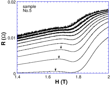
Fig.4 shows the resistance vs. field for different driving currents for sample No.5 (0.75m in thickness). (The noise at high driving current may be caused by the shunt current in the silver paint voltage contacts since the sample is very thin.) The sample No.5 was peeled off from sample No.2 using clear sticky tape (the tape can be dissolved in toluene) and has dimensions 1.0mm x 0.5mm x 0.75m. For this thin sample, a well defined, although broad, resistance dip and, correspondingly, a shallow peak in , can be observed. The ratio peak-/onset- is 1.1, and the peak (2200 A/cm2 at 1 V) is at 1.73 T. The measured phase line (not shown) of the peak effect in sample No.5 still has a negative slope, similar to Fig.3. An order-of-magnitude estimate [33] suggests that the longitudinal Larkin length is much greater than the thickness of the sample across the peak-effect regime, up to 1.80 T in this sample. We thus believe that the higher and the lower field of the peak effect in sample No.5 are results of the 2D nature of the sample.
Again, if we define the onset of the peak effect at the resistance maxima (when still discernable), a dynamic phase diagram of the peak effect can be constructed, as shown in Fig.5. There are two major differences between the dynamic phase diagrams in thick and thin samples. For low driving currents, the onset of the peak effect in thick samples seems to settle at a finite large magnetic field value, 1.78 T for sample No.2 (Fig.5 inset, a replot of Fig.4b in [23]) and 1.85 T for sample No.3 (see Fig.1). However, for the thin sample No.5, the onset of the peak effect appears to continuously decrease in field with decreasing current. In fact, the data can be fitted to an empirical form , implying that there is no end point on the field axis for the onset of the peak effect in the limit of small driving current. For large and increasing driving currents, the onset of the peak effect in thick samples tends to turn around and decrease rapidly. In thin samples, it continuously increases in field until the peak effect (resistance dip) is no longer identifiable. We suggest that this difference in driven dynamics arises from the dimensionality of the system.

Since edge dislocations are the most likely topological defects in a 2D lattice, we interpret the observed peak effect in 2D samples as a result of an elastic length crossover from the Larkin length below the peak effect to a rapidly decreasing elastic length set by thermally excited edge dislocations [17]. The lack of a lower end point on the vs. curve (Fig.5) is consistent with the common belief [34] and numerical simulations [35] that edge dislocation pairs are always unbound at arbitrary temperature in a random potential, in 2D.
If the low current part of the dynamic phase diagram suggests an unstable 2D vortex lattice at rest, the higher current behavior would suggest an unstable 3D vortex lattice in motion. Apart from the testable, trivial explanations (such as self-heating, suppression of superconduting order parameter, etc.), which have been ruled out, this result may suggest that the different dynamics of screw and edge dislocations both play a role. In a 3D vortex-line lattice, there can be both screw and edge dislocations, or combinations (e.g. loops) of the two. Unlike the edge dislocations in a 2D lattice, which are always immobilized by a Peierls potential, the screw dislocations are much more mobile since there is no discrete periodicity along the field direction [36]. Thus, when pairs of screw dislocations are generated, due to the interaction between the moving lattice and the pins, there are two competing processes. They recombine, if the motion is slow and the rate at which they are generated is low. However, if the rate of generation is higher than the rate of recombination, a Kosterlitz-Thouless- unbinding transition [37] may occur and result in a moving disordered vortex lattice full of free screw dislocations.
We are grateful to A. Houghton, D. A. Huse, M.C. Marchetti, T. Nattermann, S. Ryu, and Chao Tang for helpful discussions, and to J.M. Valles for a critical reading of the manuscript and for forcing us to clarify several important points. S.J.S. is an undergraduate UTRA Fellow.
∗An Alfred P. Sloan Research Fellow and the corresponding author. Electronic address: xsling@brown.edu.
REFERENCES
- [1] A.I. Larkin, Sov. Phys. JETP 31, 784 (1970).
- [2] D.R. Nelson and S. Seung, Phys. Rev. B 39, 9153 (1989).
- [3] A. Houghton, R.A. Pelcovits, and A. Sudb, Phys. Rev. B 40, 6763 (1989).
- [4] E.H. Brandt, Phys. Rev. Lett. 63, 1106 (1989).
- [5] M.C. Marchetti and D.R. Nelson, Phys. Rev. B 41, 1910 (1990).
- [6] D.S. Fisher, M.P.A. Fisher, and D.A. Huse, Phys. Rev. B 43, 130 (1991).
- [7] X. S. Ling and J. I. Budnick, in Magnetic Susceptibility of Superconductors and Other Spin Systems, edited by R.A. Hein, T.L. Francavilla, and D.L. Liebenberg (Plenum Press, New York, 1991), pp. 377-388.
- [8] G. D’Anna et al., Europhys. Lett. 25, 225 (1994).
- [9] W.K. Kwok et al., Phys. Rev. Lett. 73, 2614 (1994).
- [10] X.S. Ling, J.I. Budnick, and B.W. Veal, Physica C 282, 2191 (1997).
- [11] H. Safar et al., Phys. Rev. Lett. 69, 824 (1992); M. Charalambous et al., ibid. 71, 436 (1993); W.K. Kwok et al., ibid. 72, 1092 (1994); W. Jiang et al., ibid. 74, 1438 (1995).
- [12] T. Nattermann, Phys. Rev. Lett 64, 2454 (1990); T. Giamarchi and P. Le Doussal, . 72,1530 (1994); S. Ryu, A. Kapitulnik, and S. Doniach, Phys. Rev. Lett. 77, 2300 (1996); J. Kierfeld, T. Nattermann, and T. Hwa, Phys. Rev. B 55, 626 (1997); D.S. Fisher, Phys. Rev. Lett. 78, 1964 (1997).
- [13] A.B. Pippard, Phil. Mag. 19, 217 (1969).
- [14] A.I. Larkin and Yu.N. Ovchinnikov, J. Low Temp. Phys. 34, 409 (1979).
- [15] H.R. Kerchner, J. Low Temp. Phys. 50. 337 (1983).
- [16] A.I. Larkin, M.C. Marchetti, and V.M. Vinokur, Phys. Rev. Lett. 75, 2992 (1995).
- [17] C. Tang et al., Europhys. Lett. 35, 597 (1996).
- [18] E. Frey, D.R. Nelson, and D.S. Fisher, Phys. Rev. B 49, 9723 (1994).
- [19] S. Bhattacharya and M.J. Higgins, Phys. Rev. Lett. 70, 2617 (1993); Phys. Rev. B 49, 10005 (1994).
- [20] M.W. Rabin et al., Phys. Rev. B 57, R720 (1998); R.D. Merithew et al., Phys. Rev. Lett. 77, 3197 (1996).
- [21] W. Henderson et al., Phys. Rev. Lett. 7, 2077 (1996).
- [22] P.L. Gammel et al., Phys. Rev. Lett. 80, 833 (1998).
- [23] X.S. Ling, J.E. Berger, and D.E. Prober, Phys. Rev. B 57, R3249 (1998).
- [24] The thickness of the sample No.2 was inaccurately quoted as 20 m in [23]. It should be 15 m according to a SEM measurement.
- [25] D. Paine, unpublished.
- [26] R. Meier-Hirmer, H. Küpfer, and H. Scheurer, Phys. Rev. B 31, 183 (1985).
- [27] M. Daümling et al., Nature 346, 332 (1990).
- [28] B. Khaykovich et al., Phys. Rev. Lett. 76, 2555 (1996).
- [29] X.S. Ling, Ph.D. Thesis (U. of Connecticut, 1992); UMI (Microfilms), Ann Arbor, Michigan 48106.
- [30] K. Ghosh et al., Phys. Rev. Lett. 76, 4600 (1996).
- [31] A.E. Koshelev and V.M. Vinokur, Phys. Rev. Lett. 73, 3580 (1994).
- [32] M.C. Hellerqvist et al., Phys. Rev. Lett. 74, 5114 (1996).
- [33] P. Koorevaar et al., Phys. Rev. B 42, 1004 (1990).
- [34] A. Houghton, private communications.
- [35] M.J.P. Gingras and D.A. Huse, Phys. Rev. B 53, 15193 (1996).
- [36] E.H. Brandt, Phys. Rev. B 34, 6514 (1986).
- [37] J.M. Kosterlitz and D.J. Thouless, J. Phys. C 6, 1181 (1973).