Optical forces arising from phase gradients
Abstract
We demonstrate both theoretically and experimentally that gradients in the phase of a light field exert forces on illuminated objects, including forces transverse to the direction of propagation. This effect generalizes the notion of the photon orbital angular momentum carried by helical beams of light. We further demonstrate that these forces generally violate conservation of energy, and briefly discuss some ramifications of their non-conservativity.
pacs:
radiation pressure — geometric phase — computer-generated holography — light-matter interaction — optical trappingLight’s ability to exert forces has been recognized since Kepler’s De Cometis of 1619 described the deflection of comet tails by the sun’s rays. Maxwell demonstrated that the momentum flux in a beam of light is proportional to the intensity and can be transferred to illuminated objects, resulting in radiation pressure that pushes objects along the direction of propagation. This axial force has been distinguished from the transverse torque exerted by helical beams of light carrying orbital angular momentum (OAM) allen92 . We demonstrate theoretically and confirm experimentally that OAM-induced torque is a special case of a general class of forces arising from phase gradients in beams of light. We also demonstrate that phase-gradient forces are generically non-conservative, and combine them with the conservative forces exerted by intensity gradients to create novel optical traps with structured force profiles.
Our experimental demonstrations of phase-gradient forces make use of extended optical traps created through shape-phase holography roichman06 ; roichman06c ; roichman07b in an optimized polin05 holographic optical trapping dufresne98 ; grier03 system. Holographically sculpted intensity gradients enable these generalized optical tweezers ashkin86 to confine micrometer-scale colloidal particles to one-dimensional curves embedded in three dimensions. Independent control over the intensity and phase profiles along the curve then provide an ideal model system for characterizing the forces generated by phase gradients in beams of light.
I Optical forces due to phase gradients
The vector potential describing a beam of light of frequency and polarization may be written in the form
| (1) |
Assuming uniform polarization (and therefore a form of the paraxial approximation), the spatial dependence,
| (2) |
is characterized by a non-negative real-valued amplitude, , and a real-valued phase . For a plane wave propagating in the direction, , where is the light’s wavenumber, is the speed of light in vacuum, and is the refractive index of the medium. Imposing a transverse phase profile on the wavefronts of such a beam yields the more general form
| (3) |
where and where the the direction of the wavevector,
| (4) |
now varies with position. The associated electric and magnetic fields are given in the Lorenz gauge by
| (5) | ||||
| (6) |
where is the magnetic permeability of the medium, which we assume to be linear and isotropic. Following the commonly accepted Abraham formulation loudon04 , the momentum flux carried by the beam is
| (7) | ||||
| (8) |
where is the light’s intensity, and where we have employed the gauge condition . This result is somewhat controversial leonhardt06 despite a century of study, with the alternative Minkowski formulation differing from Eq. (8) by a factor of . Both formulations are believed to yield consistent results for the force on an illuminated object, but differ in their predictions for the recoil of the medium loudon04 .
Applying Eq. (3), separates naturally into an axial component and an additional component
| (9) |
transverse to the optical axis. For small objects, the transverse force arising from may be approximated as
| (10) |
where is the cross-section describing the light-matter interaction. For a dielectric sphere of radius , ashkin86 ; harada96c ,
| (11) |
where is the ratio of the particle’s refractive index, , to the medium’s, .
More than a decade ago, Allen, et al. allen92 pointed out that the helical phase profile, imbues a beam of light with an orbital angular momentum flux, , amounting to per photon. Here, is the azimuthal angle around the optical axis, and is an integer describing the wavefronts’ helical pitch. This orbital angular momentum is distinct from the photons’ intrinsic spin angular momentum allen92 ; simpson97 ; allen99 ; oneil00 ; oneil02 ; curtis03 . Through it, even linearly polarized light can exert a torque around the optical axis he95a ; friese96 ; simpson96 . Equations (9) and (10) reveal the torque exerted by helical wavefronts to be a particular manifestation of the more general class of transverse forces arising when phase gradients redirect radiation pressure.
Intensity gradients also exert forces on illuminated objects ashkin86 . In this case, the dipole moment induced in the object responds to gradients in the field, yielding a force proportional to the gradient of the intensity. For a small sphere, this has the form ashkin86 ; harada96c ,
| (12) |
Unlike the phase-gradient force, can be directed up the optical axis, and so can be used to form stable three-dimensional optical traps, despite axial radiation pressure. This is the basis for optical tweezers and related single-beam optical traps ashkin86 .
Forces due to intensity gradients are manifestly conservative ashkin92 , arising as they do from the gradient of an analytic function. Phase-gradient forces, by contrast, generally are not conservative. This is evident because
| (13) |
in general. This noteworthy property of scattering forces was pointed out by Ashkin ashkin92 , but appears not to have been emphasized subsequently in the optical trapping literature. Effects arising from non-conservative optical forces may not have drawn much attention because the experimentally accessible transverse forces can appear to be conservative in the symmetric beams that usually are considered. The phase-gradient force in a helical beam, by contrast, accelerates objects around the optical axis and so obviously does not conserve energy.
II Creating optical traps with phase gradients
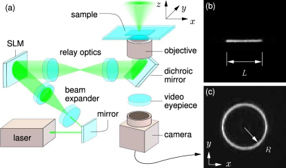
We demonstrate and characterize phase-gradient forces using the optimized holographic optical trapping technique polin05 ; dufresne98 ; roichman05a and shape-phase holography roichman06 ; roichman07b to create extended optical traps with specified profiles for both their intensity and phase. Our apparatus, shown schematically in Fig. 1(a), uses a phase-only spatial light modulator (Hamamatsu X7690-16) to imprint computer-generated holograms on the wavefronts of a slightly converging polin05 beam of light provided by a solid-state laser (Coherent Verdi 5W) operating at a vacuum wavelength of 532 nm. The modified beam is relayed to an objective lens (Nikon Plan Apo, oil immersion, NA 1.4) that focuses it into the intended three-dimensional optical trapping pattern. This objective lens is mounted in an inverted optical microscope (Nikon TE-2000U), and the trapping beam is directed into the objective’s input pupil with a wavelength selective polarizing beam splitter. Light at other wavelengths passes through the beam splitter to form images on a CCD camera (NEC TI-324AII).
The holograms used for this study are designed to bring the light to a focus along one-dimensional curves, , embedded in the three-dimensional focal volume of the objective lens. The hologram also encodes a designated intensity profile and phase profile along the arclength of . This is accomplished by numerically back-projecting goodman05 the intended field along back to the plane of the SLM to obtain the ideal complex-valued hologram, . The real-valued amplitude is defined to be non-negative by absorbing sign changes into the definition of the phase, . This facilitates encoding the complex hologram on a phase-only SLM roichman06 ; roichman06c ; roichman07b . The shape-phase algorithm assigns to the phase pixel at with a probability proportional to . An alternate phase pattern imprinted on unassigned pixels is used to divert excess light away from the intended trapping pattern. How the SLM plane is divided into assigned and unassigned domains can be tuned to minimize artifacts, improve diffraction efficiency, and optimize accuracy roichman06 ; roichman06c ; roichman07b .
The images in Figs. 1(b) and (c) show a focused line trap roichman06 and ring trap, respectively, each designed to have uniform intensity and uniform phase gradients. These images were obtained by placing a mirror in the microscope’s focal plane and capturing an image of the reflected light. Because these extended traps come to a diffraction-limited focus, their axial intensity gradients are steep enough to trap particles stably in three-dimensions against radiation pressure ashkin86 .
III Phase gradient forces in line traps
III.1 Linear phase gradients
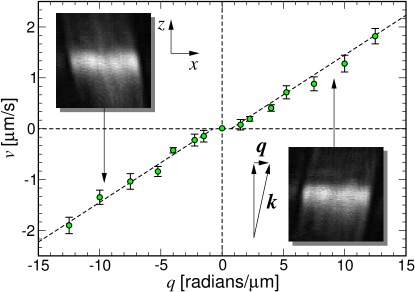
To demonstrate the phase gradient force predicted by Eq. (9), we used digital video microscopy crocker96 to track micrometer-scale colloidal spheres moving along uniformly bright line traps such as that in Fig. 1(b). The trap-forming hologram was adaptively optimized to minimize intensity variations and to incorporate linear phase gradients, , ranging from to . The effect of imposing this transverse phase gradient can be seen in axial sections roichman06c through the projected three-dimensional intensity distributions, shown inset into Fig. 2. The diffraction-limited focal line remains in the plane despite the imposed phase gradient. The beam’s direction of propagation, however, deviates from the axis by the angle . This tilt directs a component of the beam’s wave vector along the line, thereby creating a longitudinal component of the radiation pressure. The measured angle of inclination and its uniformity along confirm both the phase gradient’s magnitude and also its uniformity.
Line traps with tunable linear phase gradients were projected into aqueous dispersions of colloidal silica spheres in diameter sealed into the 40 thick gap between a glass microscope slide and a #1 glass coverslip. The line traps were focused near the samples’ midplane to minimize both interference with reflections from the glass-water interface and also hydrodynamic coupling to the walls. In that case, the spheres’ viscous drag coefficient is reasonably approximated dufresne01 by the Stokes value , where is the viscosity of water. Equations (9) and (10) then suggest that a single sphere’s speed, , along the line should be proportional to .
To test this prediction, we measured the time required for a single sphere to travel the line’s length, , as the sign of was flipped 20 times for each value of . An estimated 100 mW of light formed the trap, after accounting for losses in the optical train. The observed off-line excursions of roughly 200 nm (root-mean-squared) suggest an axial and lateral trap stiffness comparable to that of a point-like optical tweezer powered by 1 mW. Under these conditions, the trapped sphere traveled the length of the line trap in roughly 2 s when subjected to the largest phase gradients. Results obtained by systematically varying are plotted in Fig. 2, and clearly show the anticipated linear dependence, except very near . The smallest values of created too weak a force to overcome localized traps formed by uncorrected intensity variations.
III.2 Phase-gradient traps
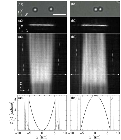
More complicated phase gradients give rise to more interesting physical effects. The particles shown in Fig. 3 also are trapped along a uniformly bright line trap of length . This line, however, has a parabolic phase profile along its length, that is predicted to create either force objects toward the center of the line, or out to the ends, depending on the choice of sign. The data in Fig. 3 also confirm this prediction. Axial sections through the projected intensity pattern show that the phase-gradient barrier results from light diverging along the line’s length, while the well results from the projection of converging rays onto the trap’s length. So long as the particles remain rigidly confined to the uniformly bright focal line, the phase-gradient force approximates a conservative one-dimensional potential energy landscape.
IV Phase gradient forces in ring traps
Like holographic line traps, holographic ring traps, such as the example in Fig. 1(c), can be endowed with arbitrary phase profiles, including the uniform azimuthal phase gradient, , that defines a helical mode. A helical profile, by itself, causes a beam to focus into a ring of light, forming a torque-exerting optical trap known as an optical vortex simpson96 ; he95 ; gahagan96 . Whereas the radius of an optical vortex is proportional to its helicity curtis03 ; sundbeck05 , holographic ring traps can be projected with any desired radius, independent of . This facilitates systematic studies of colloidal transport under varying phase gradients. Also unlike optical vortices, holographic ring traps come to a diffraction-limited focus, independent of , and therefore can trap micrometer-scale objects stably in three dimensions.
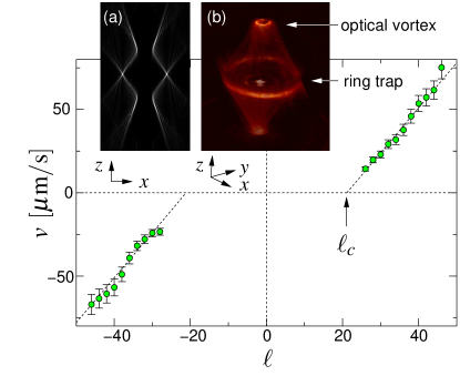
This property can be seen in the computed axial section through a holographic ring trap shown in Fig. 4(a). The section through the trap itself appears as two bright focal spots at the images mid-line. The ring’s axial intensity gradients are comparable to those of a conventional optical tweezer, and so suffice to trap objects stably in three dimensions. This ring trap features a helicity of , and so is expected to exert a torque around the optical axis proportional to . The helical wavefront topology also suppresses the beam’s axial intensity through destructive interference. Consequently, none of the light projected by the objective lens appears along the beam’s axis. Rather, it is diverted to a radius, from the axis curtis03 ; sundbeck05 . Provided that the ring trap’s radius, , exceeds , the converging helical beam focuses not only to the intended ring trap in the focal plane, but also to two conventional optical vortices above and below the ring trap. Sections through these optical vortices appear as bright regions above and below the mid-line in Fig. 4(a). Neither features the strong axial intensity gradients of the holographic ring. Consequently, neither can trap objects in three dimensions against radiation pressure. This structure also is evident in the three-dimensional reconstruction roichman06c of an experimentally projected holographic ring trap in Fig. 4(b).
We measured the free-running speed of a single colloidal silica sphere of radius as it circulated around holographic ring traps of radius projected into the midplane of a 40 thick sample. The trapped particle was subjected to azimuthal phase gradients ranging from to , and its peak speed was measured crocker96 to within 10% for each value of the helicity. The results are plotted in Fig. 4.
Like optical vortices, holographic ring trap are subject to -fold and -fold azimuthal intensity variations due to phase scaling errors lee05c . These create localized traps that compete with the intended phase-gradient force curtis03 ; lee06a . Consequently, the particle remains motionless for helicities below a threshold, . Similar pinning due to intensity gradients appears in Fig. 2. For , however, the particle’s peak speed increases linearly with , consistent with the predictions of Eqs. (9) and (10). Intermittent circulation near gives rise to large velocity fluctuations characterized by giant enhancement of the particle’s effective diffusion coefficient lee06a . Disorder in the effective force landscape also gives rise to interesting collective dynamics for multiple particles trapped on the ring, including transitions among periodic, chaotic and weakly chaotic steady states roichman07 . Phase-gradient forces in holographic ring traps therefore provide useful model systems for studying fundamental problems in nonequilibrium statistical mechanics. They also promise practical applications as the basis for microscopic pumps ladavac04a , mixers curtis02 , and optomechanical micromachines ladavac05 .
V Conclusions
The foregoing sections demonstrate that phase gradients in beams of light give rise to transverse forces arising from the redirection of radiation pressure. The existence of orbital angular momentum in beams of light and its transfer to illuminated objects can be seen to be manifestations of this general effect.
Although phase-gradient forces may appear to be conservative on restricted manifolds, they are not conservative in general. Non-conservative optical forces may give rise to interesting effects in illuminated particles’ dynamics, including departures from Boltzmann statistics for systems nominally in equilibrium. Such effects may substantially affect measurements of microscopic interactions and dynamics based on the statistics of optically trapped particles. They appear not to have been addressed in the large and rapidly growing literature in this area.
We have demonstrated that phase-gradient forces can be used to craft one-dimensional force profiles in uniformly bright holographic line traps. These can be used to probe the interactions between multiple particles trapped on a line, including both intrinsic colloidal interactions and also light-induced interactions. This application for phase-gradient forces in holographic line traps will be discussed elsewhere.
The phase-gradient force in holographic line traps is subject to the Abraham-Minkowski controversy. Extended line traps created with shape-phase holography therefore may provide useful model systems for probing how a medium influences the momentum flux of light.
Finally, it is worth mentioning that the polarization generally will vary with position in beams of light with spatially varying phase. Although optically isotropic materials are not influenced by polarization gradients, anisotropic materials can be. Polarization gradients therefore should provide additional independent avenues for exerting controlled forces on some microscopic systems.
Acknowledgements.
This work was supported by the National Science Foundation through Grant Number DMR-0606415. We are grateful to Marco Polin for enlightening conversations and to Andy Hollingsworth for help in synthesizing and characterizing monodisperse colloidal silica spheres.References
- (1) Allen, L, Beijersbergen, M. W, Spreeuw, R. J. C, & Woerdman, J. P. (1992) Phys. Rev. A 45, 8185–8189.
- (2) Roichman, Y & Grier, D. G. (2006) Opt. Lett. 31, 1675–1677.
- (3) Roichman, Y, Cholis, I, & Grier, D. G. (2006) Opt. Express 14, 10907–10912.
- (4) Roichman, Y & Grier, D. G. (2007) Proc. SPIE 6483, 64830F.
- (5) Polin, M, Ladavac, K, Lee, S.-H, Roichman, Y, & Grier, D. G. (2005) Opt. Express 13, 5831–5845.
- (6) Dufresne, E. R & Grier, D. G. (1998) Rev. Sci. Instrum. 69, 1974–1977.
- (7) Grier, D. G. (2003) Nature 424, 810–816.
- (8) Ashkin, A, Dziedzic, J. M, Bjorkholm, J. E, & Chu, S. (1986) Opt. Lett. 11, 288–290.
- (9) Loudon, R. (2004) Fortschr. Phys. 52, 1134–1140.
- (10) Leonhardt, U. (2006) Nature 444, 823–824.
- (11) Harada, Y & Asakura, T. (1996) Opt. Comm. 124, 529–541.
- (12) Simpson, N. B, Dholakia, K, Allen, L, & Padgett, M. J. (1997) Opt. Lett. 22, 52–54.
- (13) Allen, L, Padgett, M. J, & Babiker, M. (1999) Prog. Opt. 39, 291–372.
- (14) O’Neil, A. T & Padgett, M. J. (2000) Opt. Comm. 185, 139–143.
- (15) O’Neil, A. T, MacVicar, I, Allen, L, & Padgett, M. J. (2002) Phys. Rev. Lett. 88, 053601.
- (16) Curtis, J. E & Grier, D. G. (2003) Phys. Rev. Lett. 90, 133901.
- (17) He, H, Friese, M. E. J, Heckenberg, N. R, & Rubinsztein-Dunlop, H. (1995) Phys. Rev. Lett. 75, 826–829.
- (18) Friese, M. E. J, Enger, J, Rubinsztein-Dunlop, H, & Heckenberg, N. R. (1996) Phys. Rev. A 54, 1593–1596.
- (19) Simpson, N. B, Allen, L, & Padgett, M. J. (1996) J. Mod. Opt. 43, 2485–2491.
- (20) Ashkin, A. (1992) Biophys. J. 61, 569–582.
- (21) Roichman, Y, Waldron, A. S, Gardel, E, & Grier, D. G. (2005) Appl. Opt. 45, 3425–3429.
- (22) Goodman, J. W. (2005) Introduction to Fourier Optics. (McGraw-Hill, New York), 3rd edition.
- (23) Crocker, J. C & Grier, D. G. (1996) J. Colloid Interface Sci. 179, 298–310.
- (24) Dufresne, E. R, Altman, D, & Grier, D. G. (2001) Europhys. Lett. 53, 264–270.
- (25) He, H, Heckenberg, N. R, & Rubinsztein-Dunlop, H. (1995) J. Mod. Opt. 42, 217–223.
- (26) Gahagan, K. T & Swartzlander, G. A. (1996) Opt. Lett. 21, 827–829.
- (27) Sundbeck, S, Gruzberg, I, & Grier, D. G. (2005) Opt. Lett. 30, 477–479.
- (28) Lee, S.-H & Grier, D. G. (2005) Opt. Express 13, 7458–7465.
- (29) Lee, S.-H & Grier, D. G. (2006) Phys. Rev. Lett. 96, 190601.
- (30) Roichman, Y, Zaslavsky, G. M, & Grier, D. G. (2007) Phys. Rev. E 75, 020401(R).
- (31) Ladavac, K & Grier, D. G. (2004) Opt. Express 12, 1144–1149.
- (32) Curtis, J. E, Koss, B. A, & Grier, D. G. (2002) Opt. Comm. 207, 169–175.
- (33) Ladavac, K & Grier, D. G. (2005) Europhys. Lett. 70, 548–554.