Electronic structure and electric-field gradients analysis in
Abstract
Electric field gradients (EFG’s) were calculated for the compound at both and sites. The calculations were performed within the density functional theory (DFT) using the augmented plane waves plus local orbital (APW+lo) method employing the so-called LDA+U scheme. The compound were treated as nonmagnetic, ferromagnetic, and antiferromagnetic cases. Our result shows that the calculated EFG’s are dominated at the site by the Ce-4f states. An approximately linear relation is intuited between the main component of the EFG’s and total density of states (DOS) at Fermi level. The EFG’s from our LDA+U calculations are in better agreement with experiment than previous EFG results, where appropriate correlations had not been taken into account among 4f-electrons. Our result indicates that correlations among 4f-electrons play an important role in this compound and must be taken into account.
pacs:
71.20.-b, 71.28.+d, 76.80.+y, 71.27.+a, 71.20.Eh, 75.30.Mb, 75.25.+z, 31.30.Gs, 31.5.ArI Introduction
Hyperfine interactions provide sensitive physical quantities such as electric field gradients (EFG’s), which can be used to shed light experimentallyKohori1999 ; Kohori2000 and theoreticallyLali2001 ; Betsuyaku2004 into the electronic states of materials. In this paper we have focused on the as an interested system composed of strongly correlated 4f-electrons. It is a cubic heavy-fermion (HF) local moment antiferromagnetic (LMAF) system at ambient pressure with a Néel temperature of 10.1 K Lawrence1980 . This concentrated Kondo compound exhibitsMathur1998 various fascinating and unexpected physical properties. The various properties of this heavy fermion originate from the fact that one cannot assign a definite localization to the 4f-states, irrespective of the applied conditions to the compound. The unexpected physical behavior may be then attributed to the degree of localization of the 4f-electrons, i.e. the positions of the 4f-density of states (4f-DOS) with respect to the Fermi level. The position of the 4f-DOS demonstrates the degree of hybridization between localized 4f and conduction bands. The EFG quantity is extremely sensitive to the anisotropic charge distributions of the core electronsYu1991 , as well as to the aspherical electron density distribution of valance electronsSchwarz1990 , and as a result to the valance electronic structure. The EFG, thereby, can serve as a powerful gauge for measuring such a degree of localization.
J. Rusz et al.Rusz2005 very recently calculated Fermi surfaces of the regardless its antiferromagnetic ordering. Their calculations were performed in the localized extreme limit within the open core treatment Jalali2002 ; Jalali2004 . On the other delocalized extreme limit two individual groupsLali2001 ; Betsuyaku2004 calculated the EFG at the site in this compound. The calculations of the formerLali2001 and laterBetsuyaku2004 groups were performed, respectively, in the antiferromagnetic and nonmagnetic phases employing a similar method of the full-potential linearized augmented plane waves (FP-LAPW)Singh2006 .
In this paper, we have examined whether one can, using an intermediate way, improve the previous results of the localized and delocalized limits. For this purpose, we have employed the LDA+U schemeAnisimov1991 ; Anisimov1993 ; Czyyk1994 and then calculated the EFG’s at both and sites. The more advanced method of augmented plane waves plus local orbital (APW+lo)Sjstedt2000 ; Madsen2001 were used to linearize the energies. According to our knowledge, this is a first-report of the EFG calculations within the LDA+U scheme employing APW+lo method for this compound. Our spin-polarized calculations demonstrate non-zero EFG at site in the presence of spin-orbit coupling. The EFG’s, according to our knowledge, had not been previously calculated at the cubic site in this compound. The cubic symmetry of the Ce site explains why the EFG’s were less significant to be previously reported. We have emerged, nevertheless, a new result that the EFG’s are dominated at the site by 4f-states and not as usual by p-states. The goal of this work is to illustrate an approximately linear relationship between the values of EFG and density of states (DOS) at Fermi level (), viz. . According to our knowledge, such a linear relationship had not been previously observed. We also aim to justify about the tendency of the 4f-electrons in the ground state of the antiferromagnetic compound to show their degree of localization. We have also found that correlations among 4f-electrons influence semicore states of 5p-Ce.
II Details of the Calculations
All the calculations in this work were performed in the frame work of the density functional theoryHohenberg1964 ; Kohn1965 (DFT). We have taken the generalized gradient approximationPerdew1996 (GGA) into account for the exchange-correlation functional. We have employed the full-potential augmented plane waves plus local orbital (APW+lo) methodSjstedt2000 ; Madsen2001 as embodied in the WIEN2k codeBlaha1999 . The muffin-tin radii were chosen to be 2.2 Å and 2.8 Å for the In and Ce atoms, respectively. It has been allowed to be the 4s 4p 4f orbitals of the Ce and 5d 6s orbitals of In in the valance states. The expansion of the wave functions inside the spheres in lattice harmonics and in the interstitial region in plane waves were cut off by the maximum eigenvalue of and the , respectively. The cutoff for the Fourier expansion of the charge density and potential was taken to be . We used a mixing parameter of 0.001 in the Broyden’s scheme to reduce the probability of occurrence of the spurious ghostbands. A mesh of 165 special k points was taken in the irreducible wedge of the first Brillioun zone, which corresponds to the grids of in the scheme of Monkhorst-PackMonkhurst1976 . In order to perform the calculations nearly in the same accuracy for the case of magnetic super cell compared to the non-magnetic unit cell, the mesh of k points was reduced to 121 corresponding to grids. We diagonalized spin-orbit coupling (SOC) Hamiltonian in the space of scalar relativisticKoelling1997 eigenstates using a second-variational procedureMacDonald1980 imposing (111) direction on the Ce magnetic moments within a cut-off energy of 3 Ry. In order to take into account strong correlations of 4f Ce states, we have used the LDA+U methodAnisimov1991 ; Anisimov1993 ; Czyyk1994 . In one side, it is generally believed that, the on-site Coulomb repulsion U integral, as an input parameter for the LDA+U calculations, depends on the system under study. This means that the U parameter can vary for an atom, i.e. Ce in this work, from one case to the others. Here, we have used a value of 6.2 eV for the U parameter of Ce in . Fortunately, this value, U = 6.2 eV, had been before calculatedKioussis1996 for our own case of . Furthermore, on the other hand, the value obtained for the U parameter depends on the method of calculations. Unfortunately, the calculations of the U value were performed within the linear-muffin-tin-orbital (LMTO) methodKioussis1996 . Although the method of our calculations, i.e. APW+lo, is different from the LMTO, but we have noticed that for another case of face-centered-cubic the value of 6.1 eV could give satisfactory results in agreement with experimentShick2000 . The U=6.1 eV value of fcc- is not so far from the U=6.2 eV value of the compound. Therefore, we did neither more elaboration to calculate the Coulomb repulsion U within our APW+lo method, nor change this value to optimize it. Another input parameter for the LDA+U calculation is the exchange integral J. Here, we have used 0.7 eV for the J value. This J parameter can be derived using the values of 8.34 eV, 5.57 eV, and 4.12 eV for the Slater integralsShick2000 , respectively, within the following expression, which is valid for the f electrons:
| (1) |
Finally, since the factor of (U-J) appears in the total energy of the LDA+U method instead of U and J individually, we set J to zero, and let U be equal to the effective valueSawada1998 of = U - J = 5.5 eV.
III Chemical, Magnetic and Electronic Structures
III.1 Chemical Structure
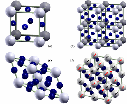
As shown in Fig. 1(a), crystallizes in the space group of with the binary-fcc prototype of . It is a cubic unit cell, where Ce atoms are located on the corners, and the In atoms on the middle of the surfaces. The point groups of Ce and In atoms are the cubic m-3m, and the non-cubic 4/mmm, respectively. The lattice parameter of the were measuredHarris1965 to be 4.69 Å. We have used this chemical structure to simulate the nonmagnetic and ferromagnetic phases.
III.2 Magnetic Structure
It has been experimentally observed that the cerium moments in this compound are aligned antiferromagnetically in adjacent (111) magnetic planes Lawrence1980 . Therefore, in order to simulate the antiferromagnetic situation, first the sides of the non-magnetic unit cell were doubled as depicted in Fig. 1(b) in all the 3 Cartesian xyz directions. We have preserved the space group of for the new magnetic supercell. The preserved fcc symmetry of the magnetic supercell causes to be reduced the number of atoms in the primitive rhombohedral magnetic unit cell, see Fig. 1(c), compared to the conventional unit cell shown in Fig. 1(b). Second, we have imposed the antiferromagnetic ordering on the magnetic moments of sites. The direction of the 4f spin in the ground state electron configuration of Ce atom, i.e. , were exchanged, i.e. , alternatively with the ordering of in the (111) direction as shown in Fig. 1(d).
III.3 Electronic Structure
We have calculated the density of states (DOS) in the lack of both spin-polarization (SP) and spin orbit coupling (SOC). This calculation has been performed using the chemical structure; Fig. 1(a). This is what we call it nonmagnetic (NM) phase from later on. The SOC was then included in two individual steps. The calculations in the first step were performed including spin-orbit interactions among only Ce-electrons. We refer to the results of this calculation by the name of ”NM+SOC(only Ce)”. The SOC was then, as the second step, included among the In-electrons as well. We call it ”NM+SOC” phase form now on. For sure, the SOC is included in both Ce and In atoms in the ”NM+SOC” phase. Our calculated DOS’s are in agreement with the previous calculationsLali2001 , and we avoid repeating them here. The SOC not only influences the semicore states of 5P Ce and 4d In, but also changes the density of states at the Fermi level (). The SOC splitting in the valance states is much smaller than the SOC splitting in the semi core states. However, the effects of the SOC would not be neglected on the results due to the fact that many physical quantities, e.g. EFG, are very sensitive to the value of the . The later point seems to be more significant for the Ce based compounds. A typical LDA/GGA calculation produces a sharp density of states for the 4f Ce, and situates it at the Fermi level. Thereby, any small changes in the sharply located 4f Ce DOS at the Fermi level can change more significantly the , and consequently the physical results.
The DOS’s were also calculated for the ferromagnetic phase in the lack of SOC, which we call it ”FM” phase. The result shows that imposing spin polarization (SP) causes to be reduced the from 141.82 states/(spin.Ry) in NM phase to 94.46 states/(spin.Ry) for spin up and to 14.90 states/(spin.Ry) for spin down in the FM phase. We have added up and down DOS’s of the FM phase. Therefore, a total reduction of 32.46 states/Ry in is occurred in going from NM to FM phase. Such a reduction affects the physical quantities that we shall discuss them in subsequent sections. We have then included the SOC in the FM phase, which we call it ”FM+SOC” phase. The result shows that including SOC gives rise to a reduction of 14.60 states/Ry from FM to FM+SOC. The shows a total reduction of 47.06 states/Ry in going from NM to FM+SOC. Hence it seems that the SP and SOC can influence physical quantities in a similar direction in this compound.
The DOS’s were calculated for the AFM state in the lack of SOC. The later state is called ”AFM(001)” phase in this paper. In the absence of the SOC there is no preferred spatial direction at the cubic site. In this case all the planes, for example (111), (001) and so on, are identical. Thus, for simplicity, the antiferromagnetic ordering, , were aligned along (001) axis. The SOC interactions were then included in the AFM(001) phase. One could introduce, at this step, a preferable direction in the presence of SOC. However, we would postpone setting up the correct direction of the cerium moments. The cerium moments were then kept still along (001) axis, which we call it ”AFM(001)+SOC” phase. The cerium moments in the AFM+SOC(001) phase were not changed to the more natural (111) direction, in order to avoid mixing the effects of SOC with the effects of spin directions in the AFM phase. The result of AFM(001) or AFM(001)+SOC shows that the picks of the semicore Ce 5p and 4d In DOS’s were nearly doubled in the AFM compared to the NM and FM phases. This is in consistent with the fact that the number of electrons are doubled in going from the chemical cell to the magnetic supercell. We have then directed the 4f Ce spins from (001) to (111) direction, and recalculated the density of states self-consistently including spin-orbit coupling. The DOS’s qualitatively were similar to those for the last case of (001) direction. However, quantitatively only changing the direction changes the values of from 167.47 sates/(spin.Ry) to 127.98 sates/(spin.Ry) for the spin up, and from 167.24 sates/(Ry.spin) to 128.24 states/(spin.Ry) for spin down. Such changes can affect the sensitive physical quantities.
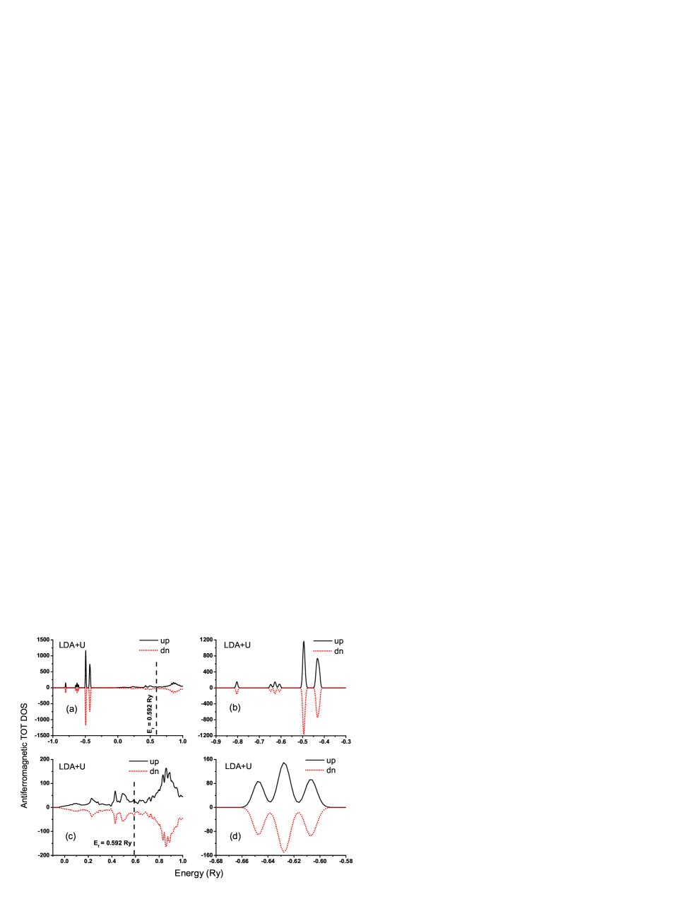
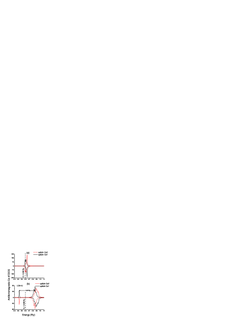
We have included an appropriate correlation among 4f Ce electrons with employing LDA+U calculations. The 4f spin orientations were preserved antiferromagnetically along (111) direction, and spin-orbit interactions were included in the LDA+U calculations. This constitutes our ”AFM(111)+SOC+LDA+U” phase. Total DOS’s of the AFM(111)+SOC+LDA+U phase are shown in Figs. 2. The result shows a significant reduction of the to 28.11 states/(spin.Ry) for both up and down spins. Total DOS’s are separately illustrated in semicore, Fig. 2(b), and valance, Fig. 2(c), regions. The DOS of the semicore region shows further splitting in one of the branches of 5p Ce DOS. This occurs in comparison with the phase of AFM(111)+SOC. Our calculated total DOS of the later phase, which is not shown here, is in complete accord with previous calculationsLali2001 . One may confirm the above mentioned further splitting by comparing Fig. 1 given in Ref. Lali2001, with our Fig. 2(a) or (b). One would more clearly observe the further splitting in Fig. 2(d). The semicore region in Fig. 2(d) is restricted to an appropriate interval, where the splitting is occurred. This shows that correlations among 4f electrons influence not only 4f Ce states directly, but also 5p Ce semicore states indirectly in this compound. There are two nonequivalent Ce atoms in the magnetic cell with opposite 4f spin directions, which are indexed as Ce1 and Ce2. The 4f DOS’s of Ce1 and Ce2 are shown in Figs. 3 for both phases of AFM(111)+SOC and AFM(111)+SOC+LDA+U. The up and down 4f-DOS’s of Ce1 are asymmetric with respect to each other, which is the case for Ce2 as well. This is in the case that in overall Ce 4f DOS is entirely symmetric regardless indexes 1 and 2. Therefore, in spite of the fact that Ce1 and Ce2 can individually impose magnetic moment, no net magnetic moment is imposed in the whole of the supercell. The 4f DOS of the AFM(111)+SOC phase is also shown in Fig. 3 (a). In this case one can more easily compare it with the later phase of AFM(111)+SOC+LDA+U shown in Fig. 3 (b). The result shows that the significant reduction in the originates mainly from the splitting between occupied and unoccupied 4f bands; see Fig. 3 (b). Such a splitting within LDA+U treatment is due to the effective Coulomb repulsion Hubbard U parameter. The 4f Ce DOS piles up in the vicinity of Fermi level within our GGA calculations. The later point is what one can clearly see for the AFM(111)+SOC phase in Fig. 3(a). This is in the case that the LDA+U calculations give rise to be constituted the 4f Ce DOS’s far from Fermi level. As shown in Fig. 3(b), including repulsion U potential energy causes to be shifted down occupied and shifted up unoccupied 4f DOS’s with respect to Fermi level. The separation energy between upper and lower 4f bands is calculated to be 0.43 Ry. Thus contributions of 4f Ce to the value of are highly decreased. The receding of the 4f Ce DOS, from the vicinity of Fermi level, indicates that the 4f electrons are going to lose their itinerant character, and as a result to gain their localized character. In order to justify about the tendency of the 4f-electrons to clarify the degree of their localization, one can compare Fig. 2(c) with Fig. 3(b). The comparison shows that the 4f Ce states play an important role and must not be ignored. The later point may be deduced from two subsequent facts. First in energy space, the 4f states as shown in Fig. 3(b) are distributed over an energy interval for which other conduction bands, e.g. In-states, as shown in Fig. 2(c) are distributed as well. Second in real space, each In atom is surrounded by 4 Ce atoms as one can see in Fig. 1(a). Consequently, the 4f states are well hybridized with the other conduction bands even after including LDA+U. Thus, the localization is reduced but not vanished by LDA+U. Therefore, we conclude that not only band-like treatment, but also open-core treatment cannot provide satisfactory results for the case of localized 4f states in this CeIn3 compound. The former treatment would not be well trusted because of putting 4f states right at the Fermi level. Thus the band-like treatment overestimates hybridization of the 4f Ce states with the other valance states. The later treatment would not be also well trusted because of confining 4f states in the core region. Thus the open-core treatment usually underestimates hybridization of 4f Ce states with the other valance states.
IV electronic specific heat
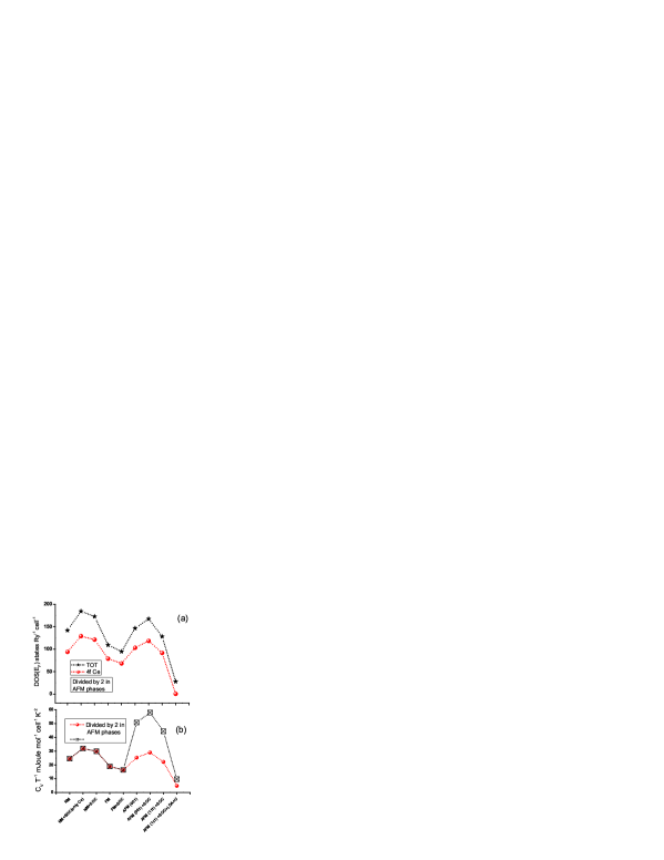
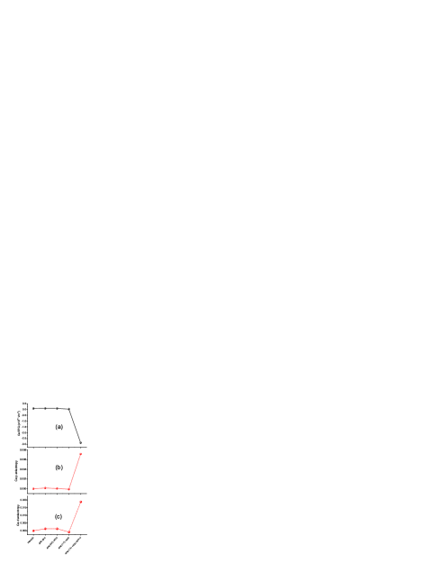
In this section, to fix ideas it seems advisable to compare the behavior of the electronic specific heats with the behavior of the through introduced phases in the preceding sec. III.3. The findings of this comparison in the next sec. V will be of relevance to the goal of this paper to realize whether or not such a comparison can be generalized to the EFG quantity as well. Therefore, we have plotted in Fig. 4(a) the calculated total and 4f Ce versus the discussed phases. The number of atoms in all the AFM phases is two times the number of other phases. The later point is also the case for the . We have then divided the by 2 for all the AFM phases. In this case, one can compare the AFM- with the of the other phases regardless the number of atoms in the magnetic and chemical cells. One performing such a comparison can focus only on the magnetic ordering effects through all the defined various phases. The behavior of this curve constitutes the backbone of this paper.
We have calculated the electronic specific heats, , in the lake of both phonon-phonon and electron-phonon interactions, and plotted the Sommerfeld linear coefficient, , in Fig. 4(b) versus all the phases. The result nicely represent the behavior of the total shown in Fig. 4(a), provided that the calculated specific heats per cell were also divided by 2 for the AFM phases. One would not be surprised observing such a perfect consistency between in one side the behavior of the specific heats and on the other hand the behavior of going through our defined phases. One would not be so, because the specific heats calculations were performed taking only electron-electron interactions into account. One can analytically omitting phonon interactions easily proveKittle2005 the formula of . This formula demonstrates a linear relation between and . According to our knowledge, it had not been analytically established such a relation between electric filed gradients (EFG’s) and . Therefore, the above sketched strategy will numerically make an opportunity in the next section trying to demonstrate an approximately linear relation between EFG and . We close this section by reporting the value of 9.74 within our LDA+U calculations. This calculated value is almost one order of magnitude less than the experimentally measured Nasu1971 value of . The discrepancy is in agreement with all the other ab initio calculations for other cases in the lack of phonon interactionsPetit2003 ; Albers1986 ; Steiner1994 .
V Electric Field Gradient
| Inte. | |||||||||||||
| Phase | SOC | LDA+U | In | Ce | In | Ce | In | Ce | |||||
| NM | No | No | 13.209 | 0 | 13.263 | 0 | -0.054 | 0 | |||||
| NM | Only Ce | No | 12.466 | 0 | 12.515 | 0 | -0.049 | 0 | |||||
| NM | Yes | No | 12.847 | 0 | 12.538 | 0 | -0.051 | 0 | |||||
| FM | No | No | 13.018 | 0 | 13.024 | 0 | -0.006 | 0 | |||||
| FM | Yes | No | (001) | 12.843 | 0.082 | 12.867 | 0.105 | -0.024 | -0.023 | ||||
| AFM | No | No | (001) | 13.027 | 0.089 | 13.032 | 0.086 | -0.005 | -0.003 | ||||
| AFM | Yes | No | (001) | 12.966 | 0.086 | 12.968 | 0.066 | -0.002 | -0.002 | ||||
| AFM | Yes | No | (111) | 12.857 | 0.029 | 12.961 | 0.040 | -0.004 | -0.011 | ||||
| AFM | Yes | Yes | (111) | 12.431 | -2.863 | 12.442 | -2.889 | -0.011 | 0.026 | ||||
| Yes | No | (111) | 12.490 | - | 12.540 | - | -0.050 | - | |||||
| unknown | 11.6 | - | - | - | - | - |
| Inte. | ||||||||||
|---|---|---|---|---|---|---|---|---|---|---|
| Phase | SOC | LDA+U | In | Ce | In | Ce | ||||
| NM | No | No | 0.1066 | 0 | -0.0060 | 0 | ||||
| NM | Only Ce | No | 0.1040 | 0 | -0.0061 | 0 | ||||
| NM | Yes | No | 0.1043 | 0 | -0.0061 | 0 | ||||
| FM | No | No | 0.0373 | 0 | -0.0050 | 0 | ||||
| FM | Yes | No | (001) | 0.0369 | 0 | -0.0052 | 0 | |||
| AFM | No | No | (001) | 0.0373 | 0.00015 | 0.0025 | 0.00130 | |||
| AFM | Yes | No | (001) | 0.0372 | 0.00005 | 0.0024 | 0.00130 | |||
| AFM | Yes | No | (111) | 0.0370 | -0.00010 | 0.0024 | -0.00085 | |||
| AFM | Yes | Yes | (111) | 0.0361 | 0.00715 | 0.0026 | 0.01880 |
The electric field gradient (EFG) is a tensor of rank 2. The EFG tensor has only 2 independent components in the principle axes system (PAS). The axes of the system were chosen such that . One can then only evaluate the main component of the EFG and the asymmetry parameter to determine the two independent components of the EFG in the PAS. In this paper we only focus on the as our calculated electric field gradients, since the asymmetry parameters are zero for our case. The main component of the EFG tensor has been calculated using the following formulaBlaha1988 :
| (2) |
where radial potential coefficient, , within LAPW method has been calculated as followsBlaha1988 ; Schwarz1990 :
| (3) | |||||
The integral yields the EFG contribution of the electrons inside and over the surface of the muffin-thin sphere with radius of . The summation yields the EFG contribution of the electrons entirely outside of the spheres. The contribution of the electrons inside the sphere is called the valance EFG, which we here denote it by . The contribution of the electrons over the surface and outside of the spheres is called the lattice EFG, which we here denote it by .
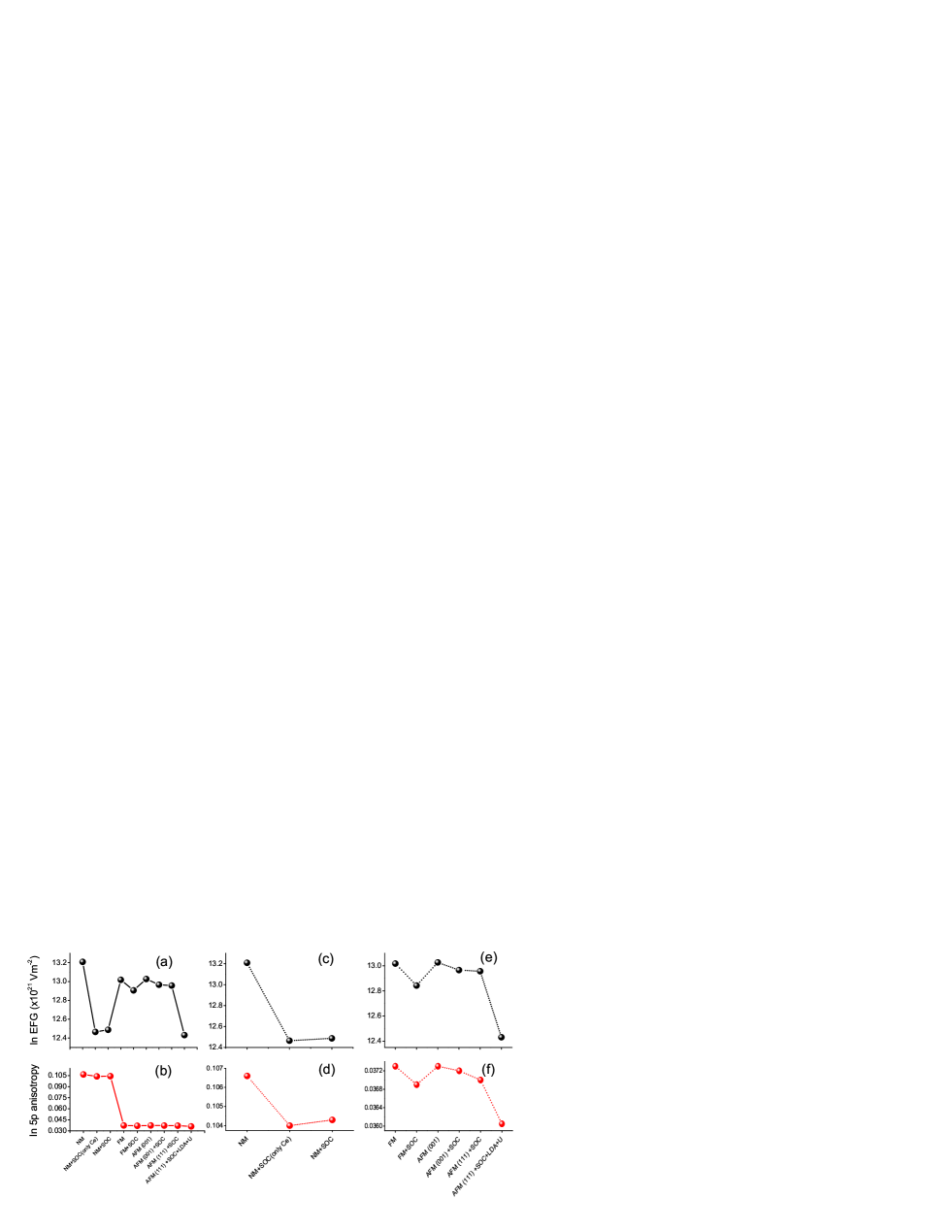
Electric field gradients, ’s, and their respective valance, ’s, and lattice, ’s, components were calculated for all the introduced phases in sec. III.3. Our results are compared with experiment and other theoretical calculations in Tab. 1. The anisotropy functions of and were also calculated and listed in Tab. 2 for all the phases. The result, in Tab. 1, shows that our calculated EFG within the phase of AFM(111)+LDA+U is in better agreement with experiment than previous calculationsKohori1999 ; Lali2001 . The better agreement confirms that we have taken more properly correlations among 4f electrons into account within our LDA+U calculations. One observes, from Tab. 2, that at In site the absolute value of is one order of magnitude greater than the absolute value of , which is not the case at Ce site. For the later case, the absolute value of is one order of magnitude smaller than the absolute value of , i.e. . We will back to this point soon. What important for us here is to study the variation of the EFG and appropriate anisotropy functions versus discussed phases to obtain a relation between EFG and . Therefore, we perform more comparisons throughout Tab. 1 and Tab. 2 illustratively in Figs. 5. We have plotted in Fig. 5(a) and in Fig. 5(b), both evaluated at site, versus all the phases. It is generally believed that, contributions to the EFG originating from p states dominate Blaha1988 . Consequently, one expects to find a linear relation between EFG and , i.e. . This is what one expects to observe looking at Fig. 5(a) and Fig. 5(b). It is hard to realize, however, the linear relation of by comparing these two figures with each other. Therefore, in order to exhibit such a linear relationship, we have separated 3 nonmagnetic phases from the other 6 magnetic phases. The and were respectively shown in Fig. 5(c) and Fig. 5(d) versus 3 nonmagnetic phases. Similar results, and , for the magnetic phases were separately shown in Fig. 5(e) and Fig. 5(f). Now one can among non magnetic phases clearly observe the linear relation between EFG and by comparing the behavior of , Fig. 5(c), with the behavior of shown in Fig. 5(d). They behave similar to each other trough non magnetic phases. This is also the case for the magnetic phases as well, since the shown in Fig. 5(e) behaves similar to shown in Fig. 5(f) through the magnetic phases. Now time seems apt to intuit that there is an approximately linear relation between EFG and , i.e. . The relation can be realized, if the behavior of the total shown in Fig. 4(a) is compared with the behavior of the shown in Fig. 5(c) and Fig. 5(e). The comparison yields the result that the EFG is approximately proportional to the . The result is obtained, because the and the vary similarly, going through all the phases. This is analogous to the used strategy in sec. IV to realize the linear relation of . Our result shows that the proportional constant is negative for the non magnetic phases, while it is positive for the magnetic phases. The former constant is negative, because the and inversely vary through non magnetic phases. They, however, vary directly versus magnetic phases resulting to the positive constant.
Furthermore, one can also conclude that the value of 4f-DOS(E can significantly influence the value of EFG. One may confirm this conclusion due to a similarity between the behavior of 4f and total shown in Fig. 4 (a). The foregoing result of ensures that the EFG can be also proportional to the 4f ; i.e. .
The later proportionality between EFG and 4f makes more crucial the method of treatment with 4f-Ce electrons. The later point describes why the value of EFG at site within the LDA+U calculation is smaller than those obtained within all the other calculations performed in the lack of LDA+U interactions. The description can be provided taking the splitting of 0.43 Ry shown in Fig. 3(b) into account between occupied and unoccupied bands due to the LDA+U treatment. The splitting gives rise to be shifted downwards the 4f DOS from the vicinity of Fermi level, and as a result to be reduced the value of 4f . The later reduction together with the discussed relation of provides the satisfactory description why the EFG is reduced within LDA+U calculations. All these support our previously concluded result in sec. III.3 concerning the important role of 4f electrons in this compound.
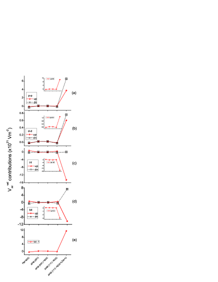
At Ce site due to its cubic point group the EFG’s are zero, as listed in Tab. 1, for all non magnetic phases and FM phase. For FM+SOC phase and all the AFM phases, however, our result shows non zero EFG values at this site. The non zero values for the EFG’s originate from the fact that SOC or magnetic ordering can give rise to a little bit deviation from cubic symmetry. One expects that the small deviation gives rise to small EFG’s. Our result, in Tab. 1, confirms the later point apart from the last phase of AFM(111)+SOC+LDA+U. For the later AFM(111)+SOC+LDA+U phase the EFG at Ce site is also practically small, but it is 2 order of magnitude larger than the other phases. To find the source of such a discrepancy, we follow our last strategy looking at the behavior of EFG and anisotropy functions through corresponded phases. The calculated EFG at Ce site can be compared with the versus magnetic phases (apart from FM phase for which EFG is exactly zero) using Fig. 6 (a) and (b). The comparison does not show similar behavior for the EFG and along the magnetic phases. To find the reason why they do not show similar behavior, now we come back to the mentioned point that at the Ce site; see Tab. 2. One first suspects, due to the larger value of than , that the behavior of EFG might be similar to the behavior of . The behaviors of EFG and are compared in Fig. 6 (a) and (c). However, they also do not show similar behavior. Therefore, we could not reproduce the behavior of the EFG using either or . For more realization, we have decomposed the EFG at Ce site into its valance contributions. The results are shown in Figs. 7 for spin up and spin down. In the Figs. 7, we have inset a figure to show sum of up and down spins for each of the valance contributions individually. The result, comparing Fig. 7 (a) and (b), shows that contributions of d-states to the EFG is one order of magnitude less than contributions of p-states. This is in the case that, as expressed before, is one order of magnitude larger than . Therefore, even for the case of , contributions to the EFG originating from p-states compared to the d-states dominate. This result is in complete accord with the calculations performed in Ref. Blaha1988, for transition metals. However, a different and important result can be emerged from comparing Fig. 7 (c) with Fig. 6 (a). The result is this that the EFG mainly originates from f-states at Ce site. We have added all the valance contributions to the EFG in Fig. 7 (d). The result shows that the behavior of EFG shown in Fig. 6 (a) is similar to total valance EFG contributions shown in Fig. 7 (c). Lattice contributions to the EFG also cannot change the similarity, because they are negligible as listed in Tab. 1. Therefore contributions to the EFG originating from f states dominate at Ce site. For sure in Fig. 7 (e) we have subtracted contributions to the EFG of f-states from total valance EFG contributions. The result, Fig. 7 (e), represents the behavior of p-anisotropy function shown in Fig. 6 (b). Such a representation reconfirms our last conclusion.
VI Conclusion
We have investigated the variations of electric field gradient (EFG’s) and their valance contributions as well as their anisotropy functions at both In and Ce sites in the for a variety of circumstances. For each of the circumstances, density of states at Fermi level () is calculated. We have found that comparing the behavior of the EFG with the behavior of versus the applied circumstances may be a useful strategy to emerge physical properties. We have found within such a strategy that the main component of the electric field gradient, , is approximately proportional to the value of total density of states at Fermi level () as well as . Despite anisotropy function of d-states is larger than the one of p-states at Ce site, contributions to the EFG originating from p-states dominate compared to d-states. This is in the case that, however, the EFG’s are dominated at the site by the 4f-states, while they are as usual dominated by p-states at the In site. The result shows that 4f Ce states are hybridized with conduction bands and play an important role which must not be ignored. Thus we have within our electronic structure calculations predicted that neither band-like treatment, nor open-core treatment can provide satisfactory results for this case. Our LDA+U calculations are in better agreement with experiment indicating the fact that correlations among 4f electrons are taken more properly into account. The correlations among 4f electrons influence not only 4f Ce states directly, but also 5p Ce semicore states indirectly in this compound.
Acknowledgements.
This work has been performed based on the research project number 821235, University of Isfahan (UI), Isfahan, Iran.References
- (1) Y. Kohori, Y. Inoue, T. Kohara, G. Tomka, and P. C. Riedi, Physica B 259-261, 103-104 (1999).
- (2) Y. Kohori, T. Kohara, Y. Yamato, G. Tomka, and P. C. Riedi, Physica B 281-282, 12-13 (2000).
- (3) M.V. Lalić, J. Mestnik-Filho, A. W. Carbonari, R. N. Saxena, and H. Haas, Phys. Rev. B 65, 054405 (2001).
- (4) K. Betsuyaku and H. Harima, J. Magn. Magn. Mater. 272-276, 187-188 (2004).
- (5) J. M. Lawrence and S. M. Shapiro, Phys. Rev. B 22, 4379 (1980); J. P. Morin, C. Vettier, J. Flouquet, M. Konczykowsky, Y. Lassailly, J. M. Mignot, and U. Welp, J. Low Temp. Phys. 70, 377 (1988); B. Benoit, J. X. Boucherle, P. Convert, J. Flouquet J. Palleau, and J. Schweizer, Solid State Commun. 34, 293 (1980).
- (6) N. D. Mathur, F. M. Grosche, S. R. Julian, I. R. Walker, D. M. Freye, R. K. W. Haselwimmer, and G. G. Lonzarich, Nature 394, 39 (1998).
- (7) J. Yu, A. J. Freeman, R. Podloucky, P. Herzig, P. Weinberger, Phys. Rev. B 43, 532 (1991).
- (8) K. Schwarz, C. Ambrosch-Draxl, P. Blaha, Phys. Rev. B 42, 2051 (1990).
- (9) J. Rusz and M. Biasini, Phys. Rev. B 71, 233103 (2005).
- (10) S. Jalali Asadabadi, S. Cottenier, H. Akbarzadeh, R. Saki, and M. Rots, Phys. Rev. B 66, 195103 (2002).
- (11) S. Jalali Asadabadi and H. Akbarzadeh, Physica B 349, 76-83 (2004).
- (12) D. J. Singh, L. Nordström, Planewaves, Pseudopotentials, and the LAPW Method, 2th edition, Springer, XIII, 134, Hardcover ISBN: 0-387-28780-9, 2006).
- (13) V. I. Anisimov and O. Gunnarsson, Phys. Rev. B 43, 7570 (1991).
- (14) V. I. Anisimov, I. V. Solovyev, M. A. Korotin, M. T. Czyżyk, and G. A. Sawatzky, Phys. Rev. B 48, 16929 (1993).
- (15) M. T. Czyżyk and G. A. Sawatzky, Phys. Rev. B 49, 14211 (1994).
- (16) E. Sjöstedt, L. Nordström, and D. J. Singh, Solid State Commun. 114, 15 (2000).
- (17) G. K. H. Madsen, P. Blaha, K. Schwarz, E. Sjöstedt, and L. Nordström, Phys. Rev. B 64, 195134 (2001).
- (18) P. Hohenberg and W. Kohn, Phys. Rev. 136, 864 (1964).
- (19) W. Kohn and L. J. Sham, Phys. Rev. 140, A1133 (1965).
- (20) J. P. Perdew, K. Burke, and M. Ernzerhof, Phys. Rev. Lett. 77, 3865 (1996).
- (21) P. Blaha, K. Schwarz, G. K. H. Madsen, D. Kvasnicka, and J. Luitz, WIEN2k, An Augmented Plane Wave + Local Orbitals Program for Calculating Crystal Properties. (Karlheinz Schwarz, Techn. Universit”at Wien, Austria), (1999), ISBN 3-9501031-1-2.
- (22) H. J. Monkhurst and J. D. Pack, Phys. Rev. B 13, 5188 (1976).
- (23) D. D. Koelling and B. N. Harmon, J. Phys. C 10, 3107 (1997).
-
(24)
A. H. MacDonald, W. E. Pickett, and D. D. Koelling,
J. Phys. C 13, 2675 (1980); Lecture note of Pavel Novak (1997) on
Spin-Orbit Coupling available from:
; see also Ref. Singh2006, . - (25) N. Kioussis, J. Thevenot, B. R. Cooper, and Q. G. Sheng, J. Appl. Phys. 79, (8) 6420 (1996).
- (26) A. B. Shick, W. E. Pickett, and A. I. Liechtenstein, arXiv: cond-mat/0001255v1, 1-4 (2000).
- (27) H. Sawada, Y. Morikawa , and K. Terakura, N. Hamada Phys. Rev. B 56, 12154–12160 (1997); S. L. Dudarev, G. A. Botton, S. Y. Savrasov, C. J. Humphreys, and A. P. Sutton, Phys. Rev. B 57, 1505–1509 (1998).
- (28) I. R. Harris and G. V. Raynor, J. Less Common Metals 9, 7 (1965).
- (29) C. Kittle, Introduction to Solid State Physics, 8th edition (Permissions Department, John wiley & Sons, Inc., river Street, Hoboken, NJ07030-5774, 2005), Chap. 6, p. 144.
- (30) S. Nasu, A. M. van Diepen, H. H. Neummann, R. S. Craig, J. Phys. Chem. Solids 32, 2772 (1971); M. Nicklas, R. Borth, E. Lengyel, P. G. Pagliuso, J. L. Sarrao, V. A. Sidorov, G. Sparn, F. Steglich, and J. D. Thomson, J. Phys.: Condens. Matter 13, L905 (2001).
- (31) L. Petit, A. Svane, W. M. Temmerman, Z. Szotek, and R. Tyer, Europhys. Lett. 62, 391-397 (2003).
- (32) R. C. Albers, A. M. Boring, N. E. Christensen, Phys. Rev. B 33, 8116 (1986).
- (33) M. M. Steiner, R. C. Albers, L. J. Sham, Phys. Rev. Let. 72, 2923 (1994).
- (34) P. Blaha and K. Schwarz, P. H. Dederichs, Phys. Rev. B 37, 2792 (1988).