Coherent optical manipulation of triplet-singlet states in coupled quantum dots

Hakan E. Türeci Institute of Quantum Electronics, ETH-Zürich, CH-8093, Zürich, Switzerland    J. M. Taylor Department of Physics, MIT, MA 02139, USA    A. Imamoglu Institute of Quantum Electronics, ETH-Zürich, CH-8093, Zürich, Switzerland
Abstract

We show that spin-orbit coupling in a quantum dot molecule allows for coherent manipulation of two electron spin states using Raman transitions. Such two-electron spin states defined by the singlet and triplet states of two exchange coupled quantum dots can have favorable coherence properties. In addition, two of the four metastable ground states in this system can be used as auxiliary states that could facilitate implementation of tasks such as mapping of spin states to that of a single propagating photon. We find that even weak spin-orbit effects — manifesting themselves as slightly different g𝑔g-factors for the electron and the hole — would allow for the coherent Raman coupling of the singlet-triplet states. We also discuss the possibilities for implementing quantum optical techniques for spin preparation and manipulation.

I INTRODUCTION

Over the past decade semiconductor quantum optical systems, implemented in quantum wells and particularly quantum dots, have been paradigmatic for the exploration of novel quantum mechanical effects in the solid state Awschalom et al. (2002). Potential applications as single photon sources Michler et al. (2000); Pelton et al. (2002) or as quantum bits for quantum information storage and processing Imamoglu (2000) have driven investigations of single quantum dots with ground states containing zero or a single electron charge. These systems bear marked resemblance to noble gas and alkali atoms. However, systems similar to alkaline-earth atoms (with two valence electrons) or homo-nuclear alkali molecules remain largely unexplored. Such systems typically have a more complex fine structure, leading to metastable spin states with useful decoherence properties Haljan et al. (2005) and have well-established semiconductor realizations Krenner et al. (2005); Stinaff et al. (2006).

In this article we examine approaches for optically coupling the four metastable ground (spin) states of a two-electron double quantum dot system via optical Raman transitions. These states, split into a singlet and triplet manifold, have demonstrated useful properties with respect to spin-related dephasing Duan and Guo (1997); Zanardi and Rasetti (1997); Lidar et al. (1998), as seen in recent experiments in electrically-controlled double quantum dots Petta et al. (2005). Our approach for coupling singlet and triplet states via optical fields can lead to the integration of optical manipulation, measurement and entanglement techniques with demonstrated approaches to controlling fine structure states in electrical quantum dots.

While we focus on the case of Zinc-Blende (III-V) semiconductor quantum dots, we find that optical coupling of ground state spins can be realized even with weak spin-orbit interaction, where a sufficient condition is that the electron and hole states have differing g𝑔g-factors; this is believed to be the case for small radius carbon nanotubes Jarillo-Herrero et al. (2004). Thus our approach for working with fine structure states can find wide application in a variety of quantum dot systems.

II Coherent optical manipulation of coupled quantum dots with strong-spin orbit effects

In this section we develop an approach to coupling singlet and triplet fine structure states of a double quantum dot system via optical Raman transitions. We rely upon the dramatic difference between exchange energies for two electrons on the same quantum dot and two electrons in separated quantum dots to provide a reliable means of using single spin selection rules to develop controlled, two-spin selection rules. We find that for doubly-charged double quantum dots with spin-orbit coupling, such as Zinc-Blende semiconductor quantum dots, polarization- and energy-selective transitions between all fine structure states are possible. This allows techniques, such as STImulated Raman Adiabatic Passage (STIRAP) to be used to initialize arbitrary superpositions of singlet and triplet spin states.

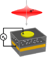
We consider here the optical transitions in a doubly-charged coupled quantum dot (CQD), a situation that can for instance be realized with an asymmetric pair of stacked InAs quantum dots embedded in a Schottky diode structure Stinaff et al. (2006) in an appropriate gate voltage regime. We assume that the left dot (L) is blue-shifted with respect to the right dot (R) and that the lowest conduction level of the right dot is detuned by ΔΔ\Delta with respect to the left one (see Fig. 1, inset). Higher orbital states can be neglected as the associated transitions are well separated in energy in the gate voltage regime of interest. For a range of gate voltages where the two dots contain a total of two electrons, by fine tuning the voltage it is possible to convert between atomic and molecular orbital states Stinaff et al. (2006), i.e., between charge states (0,2)02(0,2), (2,0)20(2,0) and (1,1)11(1,1). Labels (m,n)𝑚𝑛(m,n) here refer to the number of electrons confined in the (left,right)leftright({\rm left,right}) dot. In the presence of finite interdot tunneling and in the regime where (1,1)11(1,1) is the lowest energy charge configuration, the two resident electrons hybridize resulting in an energetically isolated singlet-triplet subspace where the effective degree of freedom is the total spin of the two electrons. This regime is denoted by (II) in Fig. 1 and in what follows we will work in this regime.

Refer to caption
Figure 1: The energy level structure of the coupled dot system as a function of the detuning ΔΔ\Delta. The charge state of the ground state follows the sequence (0,2)02(0,2), (1,1)11(1,1), (2,0)20(2,0) from left to right. Δ=ViΔsuperscriptsubscript𝑉𝑖\Delta=V_{i}^{*} (i=1,2𝑖12i=1,2) denote the anticrossing points at which the system undergoes a charge transition. The dashed lines show the triplet states |(1,1)T0ket11subscript𝑇0|(1,1)T_{0}\rangle and |(1,1)T±ket11subscript𝑇plus-or-minus|(1,1)T_{\pm}\rangle. The ground state is always in the singlet configuration at low magnetic fields. In the inset, we show the single-particle level structure of the coupled quantum dots. The detuning Δ<0Δ0\Delta<0 for the configuration shown.

In the (1,1) regime (II), the ground state manifold is given by the states |(1,1)S=12(eLeReLeR)|0ket11𝑆12superscriptsubscript𝑒𝐿absentsuperscriptsubscript𝑒𝑅absentsuperscriptsubscript𝑒𝐿absentsuperscriptsubscript𝑒𝑅absentket0|(1,1)S\rangle=\frac{1}{\sqrt{2}}(e_{L\uparrow}^{\dagger}e_{R\downarrow}^{\dagger}-e_{L\downarrow}^{\dagger}e_{R\uparrow}^{\dagger})|0\rangle, |(1,1)T0=12(eLeR+eLeR)|0ket11subscript𝑇012superscriptsubscript𝑒𝐿absentsuperscriptsubscript𝑒𝑅absentsuperscriptsubscript𝑒𝐿absentsuperscriptsubscript𝑒𝑅absentket0|(1,1)T_{0}\rangle=\frac{1}{\sqrt{2}}(e_{L\uparrow}^{\dagger}e_{R\downarrow}^{\dagger}+e_{L\downarrow}^{\dagger}e_{R\uparrow}^{\dagger})|0\rangle, |(1,1)T+=eLeR|0ket11subscript𝑇superscriptsubscript𝑒𝐿absentsuperscriptsubscript𝑒𝑅absentket0|(1,1)T_{+}\rangle=e_{L\uparrow}^{\dagger}e_{R\uparrow}^{\dagger}|0\rangle and |(1,1)T=eLeR|0ket11subscript𝑇superscriptsubscript𝑒𝐿absentsuperscriptsubscript𝑒𝑅absentket0|(1,1)T_{-}\rangle=e_{L\downarrow}^{\dagger}e_{R\downarrow}^{\dagger}|0\rangle with energies ES0=Δ+EcLR𝒥subscript𝐸subscript𝑆0Δsuperscriptsubscript𝐸𝑐𝐿𝑅𝒥E_{S_{0}}=\Delta+E_{c}^{LR}-\mathcal{J}, ET0,T±=Δ+EcLRsubscript𝐸subscript𝑇0subscript𝑇plus-or-minusΔsuperscriptsubscript𝐸𝑐𝐿𝑅E_{T_{0},T_{\pm}}=\Delta+E_{c}^{LR}, where 𝒥Te2/(ECRRECLR)𝒥superscriptsubscript𝑇𝑒2superscriptsubscript𝐸𝐶𝑅𝑅superscriptsubscript𝐸𝐶𝐿𝑅\mathcal{J}\approx T_{e}^{2}/(E_{C}^{RR}-E_{C}^{LR}). The typical energies for an InAs self-assembled quantum dot are given by ECLLECRR=VLL,LLee20meVsuperscriptsubscript𝐸𝐶𝐿𝐿superscriptsubscript𝐸𝐶𝑅𝑅subscriptsuperscript𝑉𝑒𝑒𝐿𝐿𝐿𝐿20𝑚𝑒𝑉E_{C}^{LL}\approx E_{C}^{RR}=V^{ee}_{LL,LL}\approx 20\,\,\,meV, ECLR=VLL,RRee10meVsuperscriptsubscript𝐸𝐶𝐿𝑅subscriptsuperscript𝑉𝑒𝑒𝐿𝐿𝑅𝑅10𝑚𝑒𝑉E_{C}^{LR}=V^{ee}_{LL,RR}\approx 10\,\,\,meV, where Vij,klab=𝑑𝒓𝑑𝒓φia(𝒓)φja(𝒓)Vc(|𝒓𝒓|)φkb(𝒓)φlb(𝒓)subscriptsuperscript𝑉𝑎𝑏𝑖𝑗𝑘𝑙differential-d𝒓differential-dsuperscript𝒓subscriptsuperscript𝜑𝑎𝑖𝒓subscriptsuperscript𝜑𝑎𝑗𝒓subscript𝑉𝑐𝒓superscript𝒓subscriptsuperscript𝜑𝑏𝑘superscript𝒓subscriptsuperscript𝜑𝑏𝑙superscript𝒓V^{ab}_{ij,kl}=\int\int\,d\bm{r}\,d\bm{r}^{\prime}\varphi^{a}_{i}(\bm{r})\varphi^{a}_{j}(\bm{r})V_{c}(|\bm{r}-\bm{r}^{\prime}|)\varphi^{b}_{k}(\bm{r}^{\prime})\varphi^{b}_{l}(\bm{r}^{\prime}) and φja(𝒓)subscriptsuperscript𝜑𝑎𝑗𝒓\varphi^{a}_{j}(\bm{r}) are the single-particle envelope wavefunctions on dot j=L,R𝑗𝐿𝑅j=L,R for conduction band electrons (a=e𝑎𝑒a=e) or holes (a=h𝑎a=h). The tunneling matrix element Tesubscript𝑇𝑒T_{e} appearing in the exchange splitting 𝒥𝒥\mathcal{J} is given by Te=te+VLL,LReete+VRR,LRee<1meVsubscript𝑇𝑒subscript𝑡𝑒subscriptsuperscript𝑉𝑒𝑒𝐿𝐿𝐿𝑅similar-to-or-equalssubscript𝑡𝑒subscriptsuperscript𝑉𝑒𝑒𝑅𝑅𝐿𝑅superscriptsimilar-to1𝑚𝑒𝑉T_{e}=t_{e}+V^{ee}_{LL,LR}\simeq t_{e}+V^{ee}_{RR,LR}\stackrel{{\scriptstyle<}}{{\sim}}1\,\,\,meV and connects |(1,1)Sket11𝑆|(1,1)S\rangle to |(2,0)Sket20𝑆|(2,0)S\rangle and |(0,2)Sket02𝑆|(0,2)S\rangle. Here, tesubscript𝑡𝑒t_{e} is the bare interdot electron tunneling matrix element.

Consider now a right-hand circularly polarized (σ+subscript𝜎\sigma_{+}) optical excitation with its optical axis along the heterostructure growth direction (z𝑧z-axis). This axis is defined with respect to the crystal axes of the quantum well structure on which the dots are grown, which typically defines the axis of shape asymmetry of the quantum dots (see Fig. 2). The light-matter interaction Hamiltonian in the dipole, rotating wave and envelope function approximations is given by

V+=i2Ω+(RReRhR+LReLhR)eiω+t+h.c.formulae-sequencesubscript𝑉𝑖Planck-constant-over-2-pi2subscriptΩsubscript𝑅𝑅superscriptsubscript𝑒𝑅absentsuperscriptsubscript𝑅absentsubscript𝐿𝑅superscriptsubscript𝑒𝐿absentsuperscriptsubscript𝑅absentsuperscripte𝑖subscript𝜔𝑡𝑐V_{+}=\frac{i\hbar}{2}\Omega_{+}\left(\mathcal{M}_{RR}e_{R\downarrow}^{\dagger}h_{R\Uparrow}^{\dagger}+\mathcal{M}_{LR}e_{L\downarrow}^{\dagger}h_{R\Uparrow}^{\dagger}\right)\mbox{e}^{-i\omega_{+}t}+h.c. (1)

Here, Ω+=12Le=0,Lze=0|x+iy|Lh=1,Lzh=+1subscriptΩ12quantum-operator-productformulae-sequencesuperscript𝐿𝑒0superscriptsubscript𝐿𝑧𝑒0𝑥𝑖𝑦formulae-sequencesuperscript𝐿1superscriptsubscript𝐿𝑧1\Omega_{+}=\frac{1}{\sqrt{2}}\langle L^{e}=0,L_{z}^{e}=0\,|\,x+iy\,|L^{h}=1,L_{z}^{h}=+1\rangle, where |Le=0,Lze=0ketformulae-sequencesuperscript𝐿𝑒0superscriptsubscript𝐿𝑧𝑒0|L^{e}=0,L_{z}^{e}=0\,\rangle is the periodic part of the conduction band Bloch wavefunction which has s𝑠s-character, and |Lh=1,Lzh=+1ketformulae-sequencesuperscript𝐿1superscriptsubscript𝐿𝑧1|L^{h}=1,L_{z}^{h}=+1\rangle is that of the valence band electrons (or holes) which has p𝑝p-character, while RRsubscript𝑅𝑅\mathcal{M}_{RR} and LRsubscript𝐿𝑅\mathcal{M}_{LR} are the overlaps of the electron and hole envelope wavefunctions R|Rhe{}_{e}\langle R|R\rangle_{h} and L|Rhe{}_{e}\langle L|R\rangle_{h} respectively. The implicit assumption here is that the light-hole levels and the spin-orbit split-off hole-band is energetically well-separated from the heavy-hole band denoted by |=|Jh=3/2,Jzh=3/2ketketformulae-sequencesuperscript𝐽32superscriptsubscript𝐽𝑧32|\Uparrow\rangle=|J^{h}=3/2,J_{z}^{h}=3/2\rangle, |=|Jh=3/2,Jzh=3/2ketketformulae-sequencesuperscript𝐽32superscriptsubscript𝐽𝑧32|\Downarrow\rangle=|J^{h}=3/2,J_{z}^{h}=-3/2\rangle (𝑱h=𝑳h+𝑺hsuperscript𝑱superscript𝑳superscript𝑺\bm{J}^{h}=\bm{L}^{h}+\bm{S}^{h}) so that their optical coupling can be neglected, a well-justified approximation in Zinc-Blende (III-V) semiconductor quantum dots Bahder (1990). Note that it is the correlation between the spin and spatial parts of the heavy-hole states ( |=|Lzh=1;ketketsuperscriptsubscript𝐿𝑧1|\Uparrow\rangle=|L_{z}^{h}=1;\uparrow\rangle, |=|Lzh=1;ketketsuperscriptsubscript𝐿𝑧1|\Downarrow\rangle=|L_{z}^{h}=-1;\downarrow\rangle) which enables us to use selection rules based on pseudospin conservation.

Refer to caption
Figure 2: Schematics showing the optical excitation of the CQD system embedded in a Schottky-diode structure. The light pulse Ω+(t)subscriptΩ𝑡\Omega_{+}(t) is incident along the crystal growth direction (z𝑧z-axis).

The excited state manifold of doubly charged excitons (X2superscript𝑋limit-from2X^{2-}) is eight dimensional

|(2,1)σh=eLeLeRhRσh|0\displaystyle|(2,1\uparrow)\sigma_{h}\rangle=e_{L\uparrow}^{\dagger}e_{L\downarrow}^{\dagger}e_{R\uparrow}^{\dagger}h_{R\sigma_{h}}^{\dagger}|0\rangle E1=ELLRsubscript𝐸1superscript𝐸𝐿𝐿𝑅\displaystyle E_{1}=E^{LLR}
|(2,1)σh=eLeLeRhRσh|0\displaystyle|(2,1\downarrow)\sigma_{h}\rangle=e_{L\uparrow}^{\dagger}e_{L\downarrow}^{\dagger}e_{R\downarrow}^{\dagger}h_{R\sigma_{h}}^{\dagger}|0\rangle E2=ELLRsubscript𝐸2superscript𝐸𝐿𝐿𝑅\displaystyle E_{2}=E^{LLR}
|(1,2)σh=eLeReRhRσh|0\displaystyle|(1\uparrow,2)\sigma_{h}\rangle=e_{L\uparrow}^{\dagger}e_{R\uparrow}^{\dagger}e_{R\downarrow}^{\dagger}h_{R\sigma_{h}}^{\dagger}|0\rangle E3=ELRR+Δsubscript𝐸3superscript𝐸𝐿𝑅𝑅Δ\displaystyle E_{3}=E^{LRR}+\Delta
|(1,2)σh=eLeReRhRσh|0\displaystyle|(1\downarrow,2)\sigma_{h}\rangle=e_{L\downarrow}^{\dagger}e_{R\uparrow}^{\dagger}e_{R\downarrow}^{\dagger}h_{R\sigma_{h}}^{\dagger}|0\rangle E4=ELRR+Δsubscript𝐸4superscript𝐸𝐿𝑅𝑅Δ\displaystyle E_{4}=E^{LRR}+\Delta

where σh=,subscript𝜎\sigma_{h}=\Uparrow,\Downarrow. We assume that because of the particular structure of the dots and the bias of choice, the optically generated hole always resides on the right dot within its lifetime. Here, ELLR=VLL,LLee+2VLL,RReeVLR,LRee2VLL,RRehVRR,RRehsuperscript𝐸𝐿𝐿𝑅subscriptsuperscript𝑉𝑒𝑒𝐿𝐿𝐿𝐿2subscriptsuperscript𝑉𝑒𝑒𝐿𝐿𝑅𝑅subscriptsuperscript𝑉𝑒𝑒𝐿𝑅𝐿𝑅2subscriptsuperscript𝑉𝑒𝐿𝐿𝑅𝑅subscriptsuperscript𝑉𝑒𝑅𝑅𝑅𝑅E^{LLR}=V^{ee}_{LL,LL}+2V^{ee}_{LL,RR}-V^{ee}_{LR,LR}-2V^{eh}_{LL,RR}-V^{eh}_{RR,RR} for instance and ELLR>ELRRsuperscript𝐸𝐿𝐿𝑅superscript𝐸𝐿𝑅𝑅E^{LLR}>E^{LRR} because of the e-h attraction. An additional electron tunneling matrix element connects states |(2,1)|(2,1\uparrow)\Uparrow\rangle and |(1,2)|(1\uparrow,2)\Uparrow\rangle as well as |(2,1)|(2,1\downarrow)\Uparrow\rangle and |(1,2)|(1\downarrow,2)\Uparrow\rangle, which gives rise to an anti-crossing at around the bias ΔELLRELRR1520meVΔsuperscript𝐸𝐿𝐿𝑅superscript𝐸𝐿𝑅𝑅1520𝑚𝑒𝑉\Delta\approx E^{LLR}-E^{LRR}\approx 15-20\,\,\,meV. If we operate in the (1,1) regime (II) close to V=V1𝑉superscriptsubscript𝑉1V=V_{1}^{*}, we can safely neglect any mixing of these X2superscript𝑋limit-from2X^{2-} states.

Consider the action of σ+subscript𝜎\sigma_{+} optical excitation on the (1,1)11(1,1) ground state manifold

V+|S=RR|(1,2)LR|(2,1)\displaystyle V_{+}|S\rangle=-\mathcal{M}_{RR}|(1\downarrow,2)\Uparrow\rangle-\mathcal{M}_{LR}|(2,1\downarrow)\Uparrow\rangle
V+|T0=RR|(1,2)+LR|(2,1)\displaystyle V_{+}|T_{0}\rangle=-\mathcal{M}_{RR}|(1\downarrow,2)\Uparrow\rangle+\mathcal{M}_{LR}|(2,1\downarrow)\Uparrow\rangle
V+|T+=RR|(1,2)LR|(2,1)\displaystyle V_{+}|T_{+}\rangle=\mathcal{M}_{RR}|(1\uparrow,2)\Uparrow\rangle-\mathcal{M}_{LR}|(2,1\uparrow)\Uparrow\rangle
V+|T=0subscript𝑉ketsubscript𝑇0\displaystyle V_{+}|T_{-}\rangle=0

Here, we have discarded the common factor (i/2)Ω+𝑖Planck-constant-over-2-pi2subscriptΩ(i\hbar/2)\,\Omega_{+}. Note that there is no optical transition from |Tketsubscript𝑇|T_{-}\rangle under σ+subscript𝜎\sigma_{+} circular polarization (and similarly for σsubscript𝜎\sigma_{-} and T+subscript𝑇T_{+} ). The following table illustrates the optical selection rules for transitions from |(1,1)Sket11𝑆|(1,1)S\rangle and |(1,1)T0ket11subscript𝑇0|(1,1)T_{0}\rangle.

σ+subscript𝜎\sigma_{+} σsubscript𝜎\sigma_{-}
RRsubscript𝑅𝑅\mathcal{M}_{RR} (1,2)(1\downarrow,2)\Uparrow (1,2)(1\uparrow,2)\Downarrow E1subscript𝐸1E_{1}
LRsubscript𝐿𝑅\mathcal{M}_{LR} (2,1)(2,1\downarrow)\Uparrow (2,1)(2,1\uparrow)\Downarrow E3subscript𝐸3E_{3}

Since RRLRmuch-greater-thansubscript𝑅𝑅subscript𝐿𝑅\mathcal{M}_{RR}\gg\mathcal{M}_{LR}, the upper row transitions are strongest, while the lower row may be neglected.

The e-h exchange interaction in the relevant optically excited states would be negligibly small since the unpaired electron is exchange coupled to the hole that resides in a different dot. Starting with |(1,1)S,T0ket11𝑆subscript𝑇0|(1,1)S,T_{0}\rangle, the states |(1,2)|(1\downarrow,2)\Uparrow\rangle and |(1,2)|(1\uparrow,2)\Downarrow\rangle will form the ”bright” excitons X2superscript𝑋limit-from2X^{2-}, whereas the states |(1,2)|(1\uparrow,2)\Uparrow\rangle and |(1,2)|(1\downarrow,2)\Downarrow\rangle will form the bright excitons for the |(1,1)T±ket11subscript𝑇plus-or-minus|(1,1)T_{\pm}\rangle subspace.

Refer to caption
Figure 3: Diagram showing the optical selection rules from the singlet-triplet ground state of the CQD to the intermediate excited states in a Raman spin-flip scheme. While |(1,1)Sket11𝑆|(1,1)S\rangle and |(1,1)T0ket11subscript𝑇0|(1,1)T_{0}\rangle couple to the |M|=1𝑀1|M|=1 excited state manifold, |(1,1)T+ket11subscript𝑇|(1,1)T_{+}\rangle and |(1,1)Tket11subscript𝑇|(1,1)T_{-}\rangle couple to the |M|=2𝑀2|M|=2 subspace. Here M𝑀M refers to the spin projection of the total pseudo-spin of the left electron and the right hole.

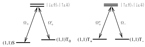
Ideally, one would like to be able to connect all the members of the (1,1)11(1,1)singlet-triplet space optically. The above discussion shows however that (T+,T)subscript𝑇subscript𝑇(T_{+},T_{-}) and (S,T0)𝑆subscript𝑇0(S,T_{0}) access different and non-overlapping subspaces of the excited state manifold via optical transitions for circular polarization. One can envision manipulating the system with a combination of a static external magnetic field and optical fields to overcome this problem.

Consider applying an in-plane magnetic field 𝑩=B𝒙^𝑩𝐵^𝒙\bm{B}=B\hat{\bm{x}}. This will mix both the ground state and the excited state manifolds. Noting that the in plane hole g𝑔g-factor is negligible, instead of rewriting the new states in the z𝑧z-representation, we will just rewrite the interaction Hamiltonian in the new electron spin basis

V+=i2Ω+(RR(eReR)hR+LR(eLeL)hR)eiω+t+h.c.formulae-sequencesubscript𝑉𝑖Planck-constant-over-2-pi2subscriptΩsubscript𝑅𝑅superscriptsubscript𝑒𝑅absentsuperscriptsubscript𝑒𝑅absentsuperscriptsubscript𝑅absentsubscript𝐿𝑅superscriptsubscript𝑒𝐿absentsuperscriptsubscript𝑒𝐿absentsuperscriptsubscript𝑅absentsuperscripte𝑖subscript𝜔𝑡𝑐V_{+}=\frac{i\hbar}{2}\Omega_{+}\left(\mathcal{M}_{RR}(e_{R\uparrow}^{\dagger}-e_{R\downarrow}^{\dagger})h_{R\Uparrow}^{\dagger}+\mathcal{M}_{LR}(e_{L\uparrow}^{\dagger}-e_{L\downarrow}^{\dagger})h_{R\Uparrow}^{\dagger}\right)\mbox{e}^{-i\omega_{+}t}+h.c. (2)

Here, eLsuperscriptsubscript𝑒𝐿absente_{L\uparrow}^{\dagger} now creates an electron with Sxe=+1/2superscriptsubscript𝑆𝑥𝑒12S_{x}^{e}=+1/2 (|Lketsubscript𝐿|\uparrow_{L}\rangle). The strong transitions now take the form

V+|S=RR(|L|L)\displaystyle V_{+}|S\rangle=-\mathcal{M}_{RR}(|\uparrow_{L}\Uparrow\rangle-|\downarrow_{L}\Uparrow\rangle)
V+|T0=RR(|L+|L)\displaystyle V_{+}|T_{0}\rangle=-\mathcal{M}_{RR}(|\uparrow_{L}\Uparrow\rangle+|\downarrow_{L}\Uparrow\rangle)
V+|T+=RR|L\displaystyle V_{+}|T_{+}\rangle=-\mathcal{M}_{RR}|\uparrow_{L}\Uparrow\rangle
V+|T=0subscript𝑉ketsubscript𝑇0\displaystyle V_{+}|T_{-}\rangle=0
V|T=RR|L\displaystyle V_{-}|T_{-}\rangle=-\mathcal{M}_{RR}|\uparrow_{L}\Downarrow\rangle

Thus, one can couple either the submanifold (S𝑆S,T0subscript𝑇0T_{0},T+subscript𝑇T_{+}) by σ+subscript𝜎\sigma_{+} light to |L|\uparrow_{L}\Uparrow\rangle or (S𝑆S,T0subscript𝑇0T_{0},Tsubscript𝑇T_{-}) by σsubscript𝜎\sigma_{-} to |L|\uparrow_{L}\Downarrow\rangle. The excitation scheme for the circular polarization case is shown in Fig. 4.
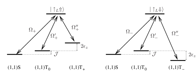
Refer to caption
Figure 4: Diagram showing the selection rules in the presence of an in-plane magnetic field. The previously derived selection rules for B=0𝐵0B=0 are no longer valid in this case, allowing for either |T+ketsubscript𝑇|T_{+}\rangle or |Tketsubscript𝑇|T_{-}\rangle state to be coupled to the same intermediate state as that of |T0ketsubscript𝑇0|T_{0}\rangle and |Sket𝑆|S\rangle. The two sets of ground state manifolds can be accessed by using either left or right hand circularly polarized fields.

Note that, σ+subscript𝜎\sigma_{+} polarized light couples |(1,1)Sket11𝑆|(1,1)S\rangle and |(1,1)T0ket11subscript𝑇0|(1,1)T_{0}\rangle to |L|\downarrow_{L}\Uparrow\rangle as well. In this regard, it is important to have a Zeeman splitting ϵZ𝒥less-than-or-similar-tosubscriptitalic-ϵ𝑍𝒥\epsilon_{Z}\lesssim\mathcal{J} (ϵZ=geμBBsubscriptitalic-ϵ𝑍superscript𝑔𝑒subscript𝜇𝐵𝐵\epsilon_{Z}=g^{e}\mu_{B}B is the single electron Zeeman splitting) that is sufficiently large so that coupling of a single spin state to a single intermediate excited optical state may be possible.

Having an auxiliary state at disposal for optical manipulation is important in the implementation of robust qubit rotations based on stimulated Raman adiabatic passage (STIRAP) Kis and Renzoni (2002). The qubits in our CQD scheme above are formed by (1,1)S11𝑆(1,1)S and (1,1)T011subscript𝑇0(1,1)T_{0}, which is a subspace that can be protected from hyper-fine induced dephasing by spin-echo techniques Petta et al. (2005). Combined with the immunity to dephasing of the intermediate state that can be achieved by STIRAP, the above described scheme seems to be well suited for generation and manipulation of qubit states for quantum information protocols in Zinc-Blende (III-V) semiconductor quantum dots.

III Optical mapping of spin states

In this section we discuss a scheme to efficiently prepare, manipulate and map spin states of a doubly charged CQD into photon polarization for long distance quantum state transfer Cirac et al. (1997).

Consider the CQD system placed inside a high-Q cavity and the gate voltage tuned such that the system is in regime (II), but close to the anti-crossing at V=V1𝑉superscriptsubscript𝑉1V=V_{1}^{*}. We furthermore apply an in-plane magnetic field. This will ensure that the states S𝑆S, T0subscript𝑇0T_{0} and T±subscript𝑇plus-or-minusT_{\pm} are well-separated in energy. Let us assume that the system is initialized to the superposition state

|Ψ=α|S+β|T0ketΨ𝛼ket𝑆𝛽ketsubscript𝑇0|\Psi\rangle=\alpha|S\rangle+\beta|T_{0}\rangle (3)

in the qubit space composed of (|S,|T0)ket𝑆ketsubscript𝑇0(|S\rangle,|T_{0}\rangle). We first map this state into the state

|Ψ=α|T+β|T0ketΨ𝛼ketsubscript𝑇𝛽ketsubscript𝑇0|\Psi\rangle=\alpha|T_{-}\rangle+\beta|T_{0}\rangle (4)

by a STIRAP sequence using σsubscript𝜎\sigma_{-} polarized light as decribed for example in Ref. Renzoni and Stenholm (2001). The Raman nature of the scattering will ensure a robust state mapping.

Refer to caption
Figure 5: The cavity assisted Raman scheme for spin-to-polarization mapping. The σsubscript𝜎\sigma_{-} polarized laser at frequency ωasubscript𝜔𝑎\omega_{a} and pulse shape Ωa(t)subscriptΩ𝑎𝑡\Omega_{a}(t) results in cavity-assisted Raman transition to |Sket𝑆|S\rangle when the two-photon resonance condition ωωa=ETES=δ1subscript𝜔subscript𝜔𝑎subscript𝐸subscript𝑇subscript𝐸𝑆subscript𝛿1\omega_{-}-\omega_{a}=E_{T_{-}}-E_{S}=\delta_{1} is satisfied. Similarly, the σ+subscript𝜎\sigma_{+} polarized laser at frequency ωbsubscript𝜔𝑏\omega_{b} and pulse shape Ωb(t)subscriptΩ𝑏𝑡\Omega_{b}(t) results in cavity-assisted Raman transition to |Sket𝑆|S\rangle when ω+ωb=ET0ES=δ2subscript𝜔subscript𝜔𝑏subscript𝐸subscript𝑇0subscript𝐸𝑆subscript𝛿2\omega_{+}-\omega_{b}=E_{T_{0}}-E_{S}=\delta_{2}. Note that the energy splitting between the excited states is negligible due to the small in-plane hole g𝑔g-factors.

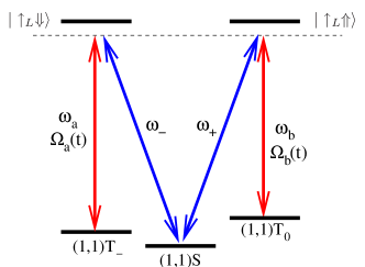
We next turn on lasers with frequencies ωasubscript𝜔𝑎\omega_{a}, ωbsubscript𝜔𝑏\omega_{b}, polarizations σsubscript𝜎\sigma_{-}, σ+subscript𝜎\sigma_{+} and time dependent Rabi frequencies Ωa(t)subscriptΩ𝑎𝑡\Omega_{a}(t) and Ωb(t)subscriptΩ𝑏𝑡\Omega_{b}(t), which are detuned by δ1subscript𝛿1\delta_{1} and δ2subscript𝛿2\delta_{2} from |T|L|T_{-}\rangle-|\uparrow_{L}\Downarrow\rangle and |T0|L|T_{0}\rangle-|\uparrow_{L}\Uparrow\rangle transitions respectively. The detunings δ1subscript𝛿1\delta_{1} and δ2subscript𝛿2\delta_{2} are carefully chosen so that the transitions |L|S|\uparrow_{L}\Downarrow\rangle-|S\rangle and |L|S|\uparrow_{L}\Uparrow\rangle-|S\rangle are resonant with a pair of degenerate cavity modes ωsubscript𝜔\omega_{-} and ω+subscript𝜔\omega_{+} with orthogonal polarizations (see Fig. 5). Such cavities can be engineered using photonic band gap structures where the cavity-mode splitting can be precisely tuned by AFM oxidation so as to enforce the degeneracy condition required Hennessy et al. (2006). The two-photon resonance condition for both polarizations will result in cavity assisted Raman transition down to |Sket𝑆|S\rangle and a transfer of the original spin state (3) to the polarization of the emitted single photon via

(α|T+β|T0)|0ph|S(α|1σph+β|1σ+ph)𝛼ketsubscript𝑇𝛽ketsubscript𝑇0subscriptket0𝑝ket𝑆𝛼subscriptketsubscript1subscript𝜎𝑝𝛽subscriptketsubscript1subscript𝜎𝑝(\alpha|T_{-}\rangle+\beta|T_{0}\rangle)|0\rangle_{ph}\rightarrow|S\rangle(\alpha|1_{\sigma_{-}}\rangle_{ph}+\beta|1_{\sigma_{+}}\rangle_{ph}) (5)

The resulting photons can then be used for long-range quantum communication in a distributed network of nodes containing CQD-cavity systems. For this to work reliably, we require the Purcell-enhanced decay rate to be faster than spin dephasing rates. Experimental parameters Badolato et al. (2005) suggest this can be achieved by a factor of 100.

IV Coherent optical manipulation of coupled quantum dots with quasi-degenerate valence bands

We now show that coherent optical coupling between fine structure states of doubly-charged double quantum dots could be achieved even when the intrinsic spin-orbit coupling of the semiconductor material is weak. We will rely upon an external magnetic field and weak electron-hole symmetry breaking (differing electron and hole g𝑔g-factors) to show that all relevant Raman transitions are accessible.

Consider the possibility of optical manipulation of quantum dots where the spin-orbit effects are weak. The weakened selection rules result in the following optical interaction Hamiltonian

V+=i2Ω+RR(hR,3/2,3/2eR,1/2,1/2+13hR,3/2,1/2eR,1/2,1/223hR,1/2,1/2eR,1/2,1/2)eiω+t+h.c.formulae-sequencesubscript𝑉𝑖Planck-constant-over-2-pi2subscriptΩsubscript𝑅𝑅superscriptsubscript𝑅3232superscriptsubscript𝑒𝑅121213superscriptsubscript𝑅3212superscriptsubscript𝑒𝑅121223superscriptsubscript𝑅1212superscriptsubscript𝑒𝑅1212superscripte𝑖subscript𝜔𝑡𝑐V_{+}=\frac{i\hbar}{2}\Omega_{+}\mathcal{M}_{RR}\left(h_{R,3/2,3/2}^{\dagger}e_{R,1/2,-1/2}^{\dagger}+\frac{1}{\sqrt{3}}\,h_{R,3/2,1/2}^{\dagger}e_{R,1/2,1/2}^{\dagger}-\sqrt{\frac{2}{3}}\,h_{R,1/2,1/2}^{\dagger}e_{R,1/2,1/2}^{\dagger}\right)\mbox{e}^{-i\omega_{+}t}+h.c. (6)

Here, hR,J,Jzsuperscriptsubscript𝑅𝐽subscript𝐽𝑧h_{R,J,J_{z}}^{\dagger} creates a hole on the right dot with total angular momentum 𝑱h=𝑳h+𝑺hsuperscript𝑱superscript𝑳superscript𝑺\bm{J}^{h}=\bm{L}^{h}+\bm{S}^{h} and magnetic quantum number Jzsubscript𝐽𝑧J_{z}, while eR,1/2,σsuperscriptsubscript𝑒𝑅12𝜎e_{R,1/2,\sigma}^{\dagger} creates an electron in the conduction band with spin projection σ=±1/2𝜎plus-or-minus12\sigma=\pm 1/2. We only keep the strong, direct transition terms of the optical Hamiltonian. Considering now the action of σ+subscript𝜎\sigma_{+} optical excitation on the (1,1)11(1,1) ground state manifold, we obtain

V+|S=RR(|(1,2) 3/2,3/2+13|(1,2) 3/2,1/223|(1,2) 1/2,1/2)\displaystyle V_{+}|S\rangle=\mathcal{M}_{RR}(|(1\downarrow,2)\,3/2,3/2\rangle+\frac{1}{\sqrt{3}}\,|(1\uparrow,2)\,3/2,1/2\rangle-\sqrt{\frac{2}{3}}\,|(1\uparrow,2)\,1/2,1/2\rangle)
V+|T0=RR(|(1,2) 3/2,3/2+13|(1,2) 3/2,1/223|(1,2) 1/2,1/2)\displaystyle V_{+}|T_{0}\rangle=\mathcal{M}_{RR}(-|(1\downarrow,2)\,3/2,3/2\rangle+\frac{1}{\sqrt{3}}\,|(1\uparrow,2)\,3/2,1/2\rangle-\sqrt{\frac{2}{3}}\,|(1\uparrow,2)\,1/2,1/2\rangle)
V+|T+=RR|(1,2) 3/2,3/2\displaystyle V_{+}|T_{+}\rangle=-\mathcal{M}_{RR}|(1\uparrow,2)\,3/2,3/2\rangle
V+|T=RR(13|(1,2) 3/2,1/223|(1,2) 1/2,1/2)\displaystyle V_{+}|T_{-}\rangle=\mathcal{M}_{RR}(\frac{1}{\sqrt{3}}\,|(1\downarrow,2)\,3/2,1/2\rangle-\sqrt{\frac{2}{3}}\,|(1\downarrow,2)\,1/2,1/2\rangle)
Refer to caption
Figure 6: The energy level structure of the excited state manifold. On the left, the energies are given in units of μBBxsubscript𝜇𝐵subscript𝐵𝑥\mu_{B}B_{x}. The additional smaller splittings are due to the possibly different g𝑔g-factors of electrons and holes, i.e. nonzero ϵh,esuperscriptitalic-ϵ𝑒\epsilon^{h,e}. The states are written out explicitly in the format |Lxh,Sxh|Sxeketsuperscriptsubscript𝐿𝑥superscriptsubscript𝑆𝑥ketsuperscriptsubscript𝑆𝑥𝑒|L_{x}^{h},S_{x}^{h}\rangle|S_{x}^{e}\rangle where the electron spin refers to the left electron and the hole is on the right. The doubly occupied singlet electrons in the right quantum dot are not shown.

In principle, the degeneracy in the excited state manifold presents a problem for coherent optical protocols due to potential destructive quantum interference between different pathways. To overcome this difficulty, we consider the effect of a magnetic field. For simplicity we assume a Voigt configuration (𝑩=B𝒙^𝑩𝐵^𝒙\bm{B}=B\hat{\bm{x}}, say). Writing the Zeeman Hamiltonian as

HZ=μBBx(Lxh+ghSxh+geSxe)subscript𝐻𝑍subscript𝜇𝐵subscript𝐵𝑥superscriptsubscript𝐿𝑥superscript𝑔superscriptsubscript𝑆𝑥superscript𝑔𝑒superscriptsubscript𝑆𝑥𝑒H_{Z}=\mu_{B}\,B_{x}\cdot(L_{x}^{h}+g^{h}S_{x}^{h}+g^{e}S_{x}^{e}) (7)

where Lxhsuperscriptsubscript𝐿𝑥L_{x}^{h} and Sxhsuperscriptsubscript𝑆𝑥S_{x}^{h} are the x𝑥x-components of the hole orbital and spin angular momentum respectively. Let us take gh,e=2+ϵh,esuperscript𝑔𝑒2superscriptitalic-ϵ𝑒g^{h,e}=2+\epsilon^{h,e} with the hindsight that the spin-orbit interaction is weak. Then, one can easily see that the total angular momentum is not conserved. Thus we have to use the (Lh,Lxh,Sh,Sxh,Sxe)superscript𝐿subscriptsuperscript𝐿𝑥superscript𝑆subscriptsuperscript𝑆𝑥subscriptsuperscript𝑆𝑒𝑥(L^{h},L^{h}_{x},S^{h},S^{h}_{x},S^{e}_{x}) basis. The energy level structure is given in Fig. 6. In this basis, the optical interaction Hamiltonian is given by

V+=i2Ω+RR(HeR+HeR)+h.c.formulae-sequencesubscript𝑉𝑖Planck-constant-over-2-pi2subscriptΩsubscript𝑅𝑅superscriptsubscript𝐻superscriptsubscript𝑒𝑅absentsuperscriptsubscript𝐻superscriptsubscript𝑒𝑅absent𝑐V_{+}=\frac{i\hbar}{2}\Omega_{+}\mathcal{M}_{RR}\left(H_{\downarrow}^{\dagger}\,e_{R\uparrow}^{\dagger}+H_{\uparrow}^{\dagger}\,e_{R\downarrow}^{\dagger}\right)+h.c. (8)

where

Hσ=12hR,1,σ12hR,0,σ12hR,+1,σσ=,formulae-sequencesuperscriptsubscript𝐻𝜎12superscriptsubscript𝑅1𝜎12superscriptsubscript𝑅0𝜎12superscriptsubscript𝑅1𝜎𝜎H_{\sigma}^{\dagger}=\frac{1}{2}h_{R,-1,\sigma}^{\dagger}-\frac{1}{\sqrt{2}}h_{R,0,\sigma}^{\dagger}-\frac{1}{2}h_{R,+1,\sigma}^{\dagger}\quad\sigma=\uparrow\,,\,\downarrow (9)

The optical ground state is still given as above with the magnetic quantum numbers measured along x𝑥x and with additional Zeeman energy contributions. The Zeeman contributions also split up the excited state manifold as shown in Fig. 6. Consider for instance the transitions to the final state |f=|1,h|e=eLeReRhR,1,ket𝑓subscriptket1subscriptket𝑒superscriptsubscript𝑒𝐿absentsuperscriptsubscript𝑒𝑅absentsuperscriptsubscript𝑒𝑅absentsuperscriptsubscript𝑅1|f\rangle=|-1,\downarrow\rangle_{h}|\uparrow\rangle_{e}=e_{L\uparrow}^{\dagger}e_{R\uparrow}^{\dagger}e_{R\downarrow}^{\dagger}h_{R,-1,\downarrow}^{\dagger}. We get V+|S,T0=V+(eLeR±eLeR)=eReR(eLHeLH)subscript𝑉ket𝑆subscript𝑇0subscript𝑉plus-or-minussuperscriptsubscript𝑒𝐿absentsuperscriptsubscript𝑒𝑅absentsuperscriptsubscript𝑒𝐿absentsuperscriptsubscript𝑒𝑅absentsuperscriptsubscript𝑒𝑅absentsuperscriptsubscript𝑒𝑅absentminus-or-plussuperscriptsubscript𝑒𝐿absentsuperscriptsubscript𝐻superscriptsubscript𝑒𝐿absentsuperscriptsubscript𝐻V_{+}|S,T_{0}\rangle=V_{+}(e_{L\uparrow}^{\dagger}e_{R\downarrow}^{\dagger}\pm e_{L\downarrow}^{\dagger}e_{R\uparrow}^{\dagger})=e_{R\uparrow}^{\dagger}e_{R\downarrow}^{\dagger}(e_{L\uparrow}^{\dagger}H_{\downarrow}^{\dagger}\mp e_{L\downarrow}^{\dagger}H_{\uparrow}^{\dagger}) which imply

f|V+|S=1/2quantum-operator-product𝑓subscript𝑉𝑆12\displaystyle\langle f|V_{+}|S\rangle=1/2
f|V+|T0=1/2quantum-operator-product𝑓subscript𝑉subscript𝑇012\displaystyle\langle f|V_{+}|T_{0}\rangle=1/2
f|V+|T+=0quantum-operator-product𝑓subscript𝑉subscript𝑇0\displaystyle\langle f|V_{+}|T_{+}\rangle=0
f|V+|T=0quantum-operator-product𝑓subscript𝑉subscript𝑇0\displaystyle\langle f|V_{+}|T_{-}\rangle=0

However, if one is to consider a spin-flip Raman scattering from S𝑆S to T0subscript𝑇0T_{0} there are two available paths via intermediate states |f1=|1,h|eketsubscript𝑓1subscriptket1subscriptket𝑒|f_{1}\rangle=|-1,\downarrow\rangle_{h}|\uparrow\rangle_{e} and |f2=|1,h|eketsubscript𝑓2subscriptket1subscriptket𝑒|f_{2}\rangle=|-1,\uparrow\rangle_{h}|\downarrow\rangle_{e}. Only when the electron and hole g𝑔g-factors are different would these contributions allow a non-zero transition amplitude, otherwise the two available paths will interfere destructively. Hence it should in principle be possible to couple the states S,T0𝑆subscript𝑇0S,T_{0} to each other via two-photon processes if the electron and hole g𝑔g-factors are different. In practice, the g𝑔g-factors should be sufficiently different to ensure |μBBx(ghge)|>γsubscript𝜇𝐵subscript𝐵𝑥superscript𝑔superscript𝑔𝑒𝛾|\mu_{B}\,B_{x}(g^{h}-g^{e})|>\gamma, where γ𝛾\gamma is the broadening of the optically-excited states.

V Conclusion

We have presented a scheme for optical manipulation of the metastable singlet-triplet subspace of a doubly-charged CQD. We find that with strong as well as weak spin-orbit interactions it is possible to implement Raman spin-flip transitions between a singlet and a triplet fine-structure-split ground state. Such Raman transitions enable the implementation of arbitrary coherent rotations robustly via quantum optical techniques previously proposed for single atoms or ions.

A key issue is the identification of the conditions that need to be satisfied in order to generate a spin-flip Raman scattering within a singlet-triplet space. In the absence of spin-orbit coupling and a degenerate p-like valence band, the optical Hamiltonian is a spin-0 operator. Thus, unless the spin-conservation law is broken in the intermediate state, it will not be possible to flip S𝑆S to T0subscript𝑇0T_{0}. In the strong spin orbit case, the optical interaction Hamiltonian however is a reducible spin operator with non-zero projections on spin-1 and spin-0 subspaces (where spin is actually a pseudo-spin due to the restriction to the heavy-hole band). This particular property makes it possible to optically connect S𝑆S and T0subscript𝑇0T_{0}.

We expect that our findings will stimulate experimental research aimed at combining electrical and optical manipulation of confined spin states. The fact that optical manipulation is possible even for quantum dot structures with weak spin-orbit interaction enhances the prospects for pursuing experimental realization of quantum communication protocols in such systems.

Acknowledgements.
HET would like to thank Mete Atatüre, Jan Dreiser and Alex Högele for useful discussions.

References

  • Awschalom et al. (2002) D. D. Awschalom, N. Samarth, and D. Loss, eds., Semiconductor Spintronics and Quantum Computation (Springer-Verlag, Berlin, 2002).
  • Michler et al. (2000) P. Michler, A. Kiraz, C. Becher, W. V. Schoenfeld, P. M. Petroff, L. D. Zhang, E. Hu, and A. Imamoglu, Science 290, 2282 (2000).
  • Pelton et al. (2002) M. Pelton, C. Santori, J. Vuckovic, B. Y. Zhang, G. S. Solomon, J. Plant, and Y. Yamamoto, Physical Review Letters 89 (2002).
  • Imamoglu (2000) A. Imamoglu, Fortschr. Phys. 48, 987 (2000).
  • Haljan et al. (2005) P. C. Haljan, P. J. Lee, K.-A. Brickman, M. Acton, L. Deslauriers, and C. Monroe, Physical Review A 72, 062316 (2005).
  • Krenner et al. (2005) H. J. Krenner, M. Sabathil, E. C. Clark, A. Kress, D. Schuh, M. Bichler, G. Abstreiter, and J. J. Finley, Physical Review Letters 94, 057402 (2005).
  • Stinaff et al. (2006) E. A. Stinaff, M. Scheibner, A. S. Bracker, I. V. Ponomarev, V. L. Korenev, M. E. Ware, M. F. Doty, T. L. Reinecke, and D. Gammon, Science 311, 636 (2006).
  • Zanardi and Rasetti (1997) P. Zanardi and M. Rasetti, Phys. Rev. Lett. 79, 3306 (1997).
  • Lidar et al. (1998) D. A. Lidar, I. L. Chuang, and K. B. Whaley, Phys. Rev. Lett. 81, 2594 (1998).
  • Duan and Guo (1997) L.-M. Duan and G.-C. Guo, Phys. Rev. Lett. 79, 1953 (1997).
  • Petta et al. (2005) J. R. Petta, A. C. Johnson, J. M. Taylor, E. A. Laird, A. Yacoby, M. D. Lukin, C. M. Marcus, M. P. Hanson, and A. C. Gossard, Science 309, 2180 (2005).
  • Jarillo-Herrero et al. (2004) P. Jarillo-Herrero, S. Sapmaz, C. Dekker, L. P. Kouwenhoven, and H. S. J. van der Zant, Nature 429, 389 (2004).
  • Bahder (1990) T. B. Bahder, Physical Review B 41, 11992 (1990).
  • Kis and Renzoni (2002) Z. Kis and F. Renzoni, Physical Review A 65 (2002).
  • Cirac et al. (1997) J. I. Cirac, P. Zoller, H. J. Kimble, and H. Mabuchi, Physical Review Letters 78, 3221 (1997).
  • Renzoni and Stenholm (2001) F. Renzoni and S. Stenholm, Optics Communications 189, 69 (2001).
  • Hennessy et al. (2006) K. Hennessy, C. Hogele, E. Hu, A. Badolato, and A. Imamoglu, Applied Physics Letters 89 (2006).
  • Badolato et al. (2005) A. Badolato, K. Hennessy, M. Atature, J. Dreiser, E. Hu, P. M. Petroff, and A. Imamoglu, Science 308, 1158 (2005).