Does Nature Allow Negative Refraction with Low Losses in Optical Region?
Abstract
From the fundamental requirement of causality, we derive a rigorous criterion of negative refraction (left-handedness). This criterion imposes the lower limits on the electric and magnetic losses in the region of the negative refraction. If these losses are eliminated or significantly reduced by any means, including the compensation by active (gain) media, then the negative refraction will disappear. This theory can be particularly useful in designing new left-handed materials: testing the expected polarizabilities of a medium against this criterion would check the compliance with the causality and verify the design feasibility.
pacs:
78.67.-n, 71.45.Gm, 73.20.MfThere has been recently a significant attention devoted to the so called left-handed materials (LHM), which are also called negative-refraction media Pendry (2003); Smith and Kroll (2000); Smith et al. (2000); Shelby et al. (2001); Houck et al. (2003); Parazzoli et al. (2003); Lagarkov and Kissel (2004); Zhang et al. (2005); Grigorenko et al. (2005); Shalaev et al. (2005); Dolling et al. (2006); Leonhardt (2006); Pendry et al. (2006). In such materials, the directions of energy transfer and wave-front propagation are opposite. This leads to remarkable electromagnetic (optical) properties such as refraction at surfaces that is described by a negative refraction index . This, in turn, causes a flat slab of a left-handed material with to act as a “perfect lens creating, without reflections at the surfaces, a non-distorted image. This is a so-called Veselago lens Veselago (1968). Moreover, such a lens can also build an image in the near field Pendry (2000). Optical losses in LHMs are detrimental to their performance. These losses for LHMs in the near-infrared and visible region are significant Zhang et al. (2005); Grigorenko et al. (2005); Shalaev et al. (2005); Dolling et al. (2006), which drastically limits their usefulness. There have been proposals to compensate these losses with optical gain Nezhad et al. (2004); Popov and Shalaev (2006a), which appears to be a way to resolve this problem. In this Letter, we show that compensating the optical losses, which implies significantly reducing the imaginary part of the dielectric permittivity and magnetic permeability , will necessarily change also the real parts of these quantities in such a way that the negative refraction disappears. This follows from the dispersion relations, i.e., ultimately, from the fundamental principle of causality.
A proposal to add a gain medium to a metal nanosystem to create a nanoplasmonic counterpart of laser (spaser) in the near-infrared and visible spectral region has been introduced in Refs. Bergman and Stockman, 2003; Stockman and Bergman, 2003. Earlier, a THz quantum cascade laser with surface-polariton resonator has been created Colombelli et al. (2001). A possibility to compensate a small fraction of optical losses in plasmonic propagation by gain as a first step toward creation a spaser has been experimentally shown Seidel et al. (2005). Using optical gain to compensate losses in the plasmonic “perfect lens” has been proposed Ramakrishna and Pendry (2003). The interest to the compensation of losses in the metal plasmonic systems by the optical gain has attracted recently a great deal of attention in conjunction with the formidable problem of creating LHMs in the near-infrared and visible spectrum with low losses Nezhad et al. (2004); Popov and Shalaev (2006a, b). This compensation of losses in LHMs by gain appears to be very attractive since the existing implementations of the LHMs in the optical region suffer from large optical losses: , where is the wave vector, so a wave propagates just a few periods in such a medium before extinction reduces its intensity several times Zhang et al. (2005); Grigorenko et al. (2005); Shalaev et al. (2005); Dolling et al. (2006). Apart from the active approach based on the gain media, there is also a possibility to use different materials or to nanostructure a medium to lower the optical losses.
However, it is impossible to reduce the optical losses without affecting the real part of the dielectric and magnetic responses because of the requirements of causality leading to the familiar Kramers-Kronig dispersion relations (see, e.g., Ref. Landau and Lifshitz, 1984). In this Letter, we derive similar dispersion relations for the squared refractive index. Using them we show that a significant reduction in the optical losses at and near the observation frequency will necessarily eliminate the negative refraction.
The Kramers-Kronig relations follow from the causality of the dielectric response function in the temporal domain. Then one can prove that in the frequency domain permittivity does not have singularities in the upper half-plane of the complex variable . From this and the limit for , one derives the conventional Kramers-Kronig dispersion relation for the dielectric function. For the same causality reason, magnetic permeability does not have singularities in the upper half-plane of complex . Since also for , permeability satisfies a similar dispersion relation. Note the requirement of the response linearity is essential: nonlinear and saturated polarizabilities generally do not satisfy the Kramers-Kronig relations. Boyd (2003) We will below consider systems including gain media; in those cases we assume that the optical reponses to the signal (observed) radiation are linear. This of course requires the signal to be weak enough to ensure the linearity of the responses to it and the applicability of the Kramers-Kronig relations.
We consider a material to be an effective medium characterized by macroscopic permittivity and permeability . The squared complex refraction index has exactly the same analytical properties as and separately: does not have singularities in the upper half plane of complex and for . Therefore, absolutely similar to the derivation of the Kramers-Kronig relations for the permittivity or permeability (see, e.g., Ref. Landau and Lifshitz, 1984), we obtain a dispersion relation for ,
| (1) |
where denotes the principal value of an integral.
Note that in contrast to , refractive index may possess singularities in the upper half plane and thus is generally not causal; this is true, in particular, when optical gain is present Skaar (2006). The refractive index per se does not enter the Maxwell equations; it is not a susceptibility, and it does not have to obey the causality, while does. This theory is based on , not ; the non-causality of is irrelevant for its purposes.
Now we assume that at the observation frequency the material is transparent (e.g., the losses are compensated by gain), i.e., with any required accuracy. Then the principal value in the right-hand side of Eq. (1) can be omitted. Multiplying both sides of this equation by and differentiating over (one can differentiate under the integral over as a parameter, because the point is not singular anymore), we obtain
| (2) |
The left-hand side of this equation can be expressed in terms of the phase velocity , where wave vector and is speed of light, and group velocity . In this way, we obtain
| (3) |
where , and, similarly, , ; .
In the case of the negative refraction, the directions of the phase and energy propagation are opposite, therefore . Consequently, we obtain from Eq. (3) a rigorous criterion of the negative refraction with no (or low) loss at the observation frequency as
| (4) |
This criterion directly imposes the lower bounds on the dielectric losses [], overlapping with the magnetic plasmonic behavior [] and the magnetic losses [] overlapping with the electric plasmonic behavior []. The denominator makes the integral to converge for large; it would have diverged at if the integrand did not vanish at that point. Thus, the major contribution to Eq. (4) comes from the lossy, overlapping electric and magnetic resonances close to observation frequency .
The stability of the system requires that no net gains are present at any frequency, i.e., and everywhere. Landau and Lifshitz (1984) There is a known condition of negative refraction Depine and Lakhtakia (2004) . This condition is always satisfied in the region of left-handedness where and . Thus, this condition is trivial: in contrast to Eq. (4), it does not impose a lower limit on the losses.
In the absence of magnetic resonances, in the optical region and . Then it is obvious than the integral in the left-hand side of Eq. (4) is strictly positive and this criterion is not satisfied, i.e., the negative refraction is absent. In the presence of a magnetic resonance, in a part of its region and ; thus the criterion (4) can, in principle, be satisfied. However, this requires non-zero losses: and/or .
To satisfy the transparency requirement at the observation frequency, , one may attempt to add a gain to exactly cancel out the losses at this frequency Popov and Shalaev (2006a, b). Is it possible from the positions of causality? Because the loss should nowhere be negative, it is obvious that it must have the zero minimum at frequency . The corresponding resonant contribution to the permittivity close to resonance frequency has the form
| (5) |
Here is the relaxation rate that depends on frequency due to the loss compensation. At the observation frequency this loss is completely compensated, , and it has a minimum: and . However, it follows from this equation that has an extra pole at a complex frequency
| (6) |
This pole is situated in the upper half plane, which violates causality. Because the form of Eq. (5) is rather general close to the resonance, we conclude that in this manner it is impossible to compensate the losses.
It is still possible that both the magnetic resonance and electric plasmonic behavior are present, but their losses are compensated by an active-medium gain. However, such compensation must take place not only at the observation frequency , but for the entire region of such resonances assuming their homogeneous nature. This means that in Eq. (4) whenever , we have and . However, in this case the contribution of this region to the integral in Eq. (4) vanishes, and the contribution of the region of normal optical magnetic behavior () is always positive. Consequently, the negative-refraction criterion is violated, which implies the absence of the negative refraction.
To obtain the negative refraction, the losses in the magnetic resonance region not only should be present, but they should be significant not only to overcome the positive contribution of the non-resonant region to the integral in Eq. (4), but actually to make it less than . Thus, significantly reducing by any means, passive or active (by gain), the losses of the negative-refraction resonances will necessarily eliminate this negative refraction itself. Fundamentally, this stems from the fact that the imaginary part and real part of the squared index of refraction are not independent but must satisfy the requirements imposed by the principle of causality.
One has to explore also a possibility to satisfy the criterion (4) with low losses at the working frequency by having a left-handed resonance somewhere else at some resonance frequency remote from to satisfy Eq. (4). The contribution of such a remote resonance to the integral in Eq. (4) can be approximated as
| (7) |
Here is the resonant contribution to the squared index. It is assumed that it decreases rapidly enough when , which is the expression of its resonant behavior. In this case, it is possible to extend the integral in this equation over the entire region, as indicated. As required by the causality, does not have any singularities in the upper half plane of . This integral can be closed by an infinite arc in the upper half-plane, which gives the zero result due to this absence of the singularities there. Hence, the distant resonances do not contribute to the negative-refraction criterion (4). This completes the proof that zero (or, very low) losses at and near the observation frequency are incompatible with the negative refraction.
We point out that in reality these losses do not have to be zero to eliminate the negative refraction. If they are merely much smaller that the losses in the adjacent regions that result in the positive contribution to the integral in criterion (4), then the negative refraction will be absent. In the microwave region, these losses can actually be quite small, but not so in the optical region.
Simple, exactly solvable, and convincing illustrations of the above theory are provided by the negative refraction of surface plasmon polaritons (SPPs) in films with nanoscale thickness. Note that it is a two-dimensional refraction but our consideration is based on the principle of causality and is general, applicable to refraction in spaces of arbitrary dimensions. We emphasize the the examples to follow do not provide a proof but serve merely as illustrations of the above-given proof.
Consider a flat layer with nanoscale thickness made of a material with dielectric permittivity embedded between two half-spaces of materials with permittivities and . The dispersion relation, i.e., wave vector as a function of or vice versa, of the waves (SPPs) bound to the nanolayer can be found from an exact, analytical transcendental equation
| (8) |
where .
As the first example, we mention a semi-infinite metal (silver) covered with a nanolayer of dielectric with a half-space of another dielectric covering it. Karalis et al. (2005); Stockman (2006) This system possesses an extended spectral region of negative refraction Stockman (2006); however, in this region the SPP losses are so high that the propagation is actually absent, in accord with the above-presented theory.
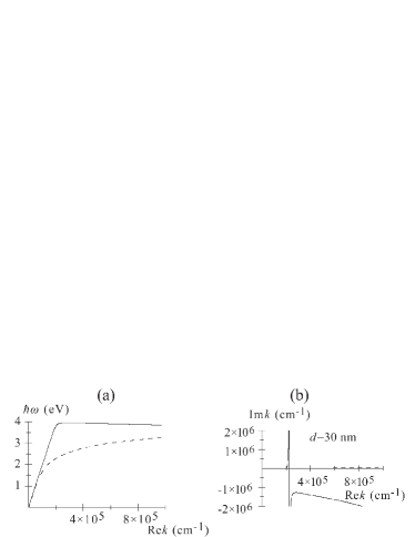
Another exactly solvable example of negative refraction also described by Eq. (8) is given by SPPs in a metal film of a nanoscopic thickness embedded in a dielectric. There are two metal-dielectric interfaces and, correspondingly, two modes of SPPs in this system. Because there is symmetry with respect to the reflection in the middle plain, these SPP modes are classified according to their magnetic-field parity: symmetric and antisymmetric. As an example, we consider a silver film with thickness nm in vacuum. The corresponding dispersion relations are shown in Fig. 1. As we see from panel (a), the symmetric SPPs have regions of both the positive refraction () and negative refraction (), while the antisymmetric SPPs possess only the positive refraction. The optical losses are shown in Fig. 1(b). For most of the positive-refraction region of the symmetric SPPs and in the entire spectral range of the antisymmetric SPPs, these losses are relatively very small: . However, for the symmetric SPPs (the solid line) close to the negative-refraction region, the losses dramatically increase by orders of magnitude. Inside the negative-refraction region, they are extremely high, , so the propagation is overdamped and actually absent, in the full agreement with the conclusions of the present theory. 111In this region describing the propagation of energy opposite to the wave vector.
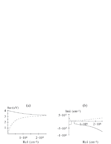
Yet another system that supports the negative-refraction SPPs is a dielectric nanolayer embedded in a metal Shin and Fan (2006). This system is also symmetric and possesses two metal-dielectric interfaces. Therefore it supports two branches of SPPs that are characterized by parity. The corresponding dispersion relations are displayed in Fig. 2. The real parts of these dispersion relations as functions for these two types of modes are shown in panel(a). From it we see that in the entire spectral region the symmetric SPPs (dashed line) have normal, positive refraction (), while the antisymmetric SPPs (solid line) are negative-refracting (). The corresponding losses are displayed in Fig. 2(b). We note that the losses of the positive-refraction, symmetric mode (dashed line) are relatively small in the entire region, . In a sharp contrast, for the antisymmetric, negative-refraction mode (solid line), the losses for small wave vectors are very high, , so the wave propagates through only a few periods before it dissipates. The apparent discontinuity of the corresponding curve at small momenta is due to the failure of the numerical procedure to find a root of characteristic equation (8), which a consequence of the fact that a good, propagating SPP mode in this spectral region does not exist.
To conclude, from the fundamental principle of causality, we have derived a dispersion relation (1) for the squared refraction index. From it, assuming a low loss at the observation frequency, we have derived a criterion (4) of the negative refraction. We have shown that the low loss at and near the observation frequency is incompatible with the existence of the negative refraction 222The low loss is understood as significantly lower than in the spectral regions adjacent to the magnetic resonance, or the loss that would have be present if the gain medium compensation were not introduced.. While at the THz region the losses may not be significant, they are very large in the optical region. The loss compensation or significant reduction will necessarily lead to the disappearance of the negative refraction itself due to the dispersion relation dictated by the causality.
This work was supported by grants from the Chemical Sciences, Biosciences and Geosciences Division of the Office of Basic Energy Sciences, Office of Science, U.S. Department of Energy, a grant CHE-0507147 from NSF, and a grant from the US-Israel BSF.
References
- Pendry (2003) J. B. Pendry, Opt. Express 11, 639 (2003).
- Smith and Kroll (2000) D. R. Smith and N. Kroll, Phys. Rev. Lett. 85, 2933 (2000).
- Smith et al. (2000) D. R. Smith, W. J. Padilla, D. C. Vier, S. C. Nemat-Nasser, and S. Schultz, Phys. Rev. Lett. 84, 4184 (2000).
- Shelby et al. (2001) R. A. Shelby, D. R. Smith, S. C. Nemat-Nasser, and S. Schultz, Appl. Phys. Lett. 78, 489 (2001).
- Houck et al. (2003) A. A. Houck, J. B. Brock, and I. L. Chuang, Phys. Rev. Lett. 90, 137401 (2003).
- Parazzoli et al. (2003) C. G. Parazzoli, R. B. Greegor, K. Li, B. E. C. Koltenbah, and M. Tanielian, Phys. Rev. Lett. 90, 107401 (2003).
- Lagarkov and Kissel (2004) A. N. Lagarkov and V. N. Kissel, Phys. Rev. Lett. 92, 077401 (2004).
- Zhang et al. (2005) S. Zhang, W. Fan, N. C. Panoiu, K. J. Malloy, R. M. Osgood, and S. R. J. Brueck, Phys. Rev. Lett. 95, 137404 (2005).
- Grigorenko et al. (2005) A. N. Grigorenko, A. K. Geim, H. F. Gleeson, Y. Zhang, A. A. Firsov, I. Y. Khrushchev, and J. Petrovic, Nature 438, 335 (2005).
- Shalaev et al. (2005) V. M. Shalaev, W. S. Cai, U. K. Chettiar, H. K. Yuan, A. K. Sarychev, V. P. Drachev, and A. V. Kildishev, Opt. Lett. 30, 3356 (2005).
- Dolling et al. (2006) G. Dolling, C. Enkrich, M. Wegener, C. M. Soukoulis, and S. Linden, Science 312, 892 (2006).
- Leonhardt (2006) U. Leonhardt, Science 312, 1777 (2006).
- Pendry et al. (2006) J. B. Pendry, D. Schurig, and D. R. Smith, Science 312, 1780 (2006).
- Veselago (1968) V. G. Veselago, Soviet Physics Uspekhi 10, 509 (1968).
- Pendry (2000) J. B. Pendry, Phys. Rev. Lett. 85, 3966 (2000).
- Nezhad et al. (2004) M. P. Nezhad, K. Tetz, and Y. Fainman, Opt. Express 12, 4072 (2004).
- Popov and Shalaev (2006a) A. K. Popov and V. M. Shalaev, Opt. Lett. 31, 2169 (2006a).
- Bergman and Stockman (2003) D. J. Bergman and M. I. Stockman, Phys. Rev. Lett. 90, 027402 (2003).
- Stockman and Bergman (2003) M. I. Stockman and D. J. Bergman, in Proceedings of SPIE: Complex Mediums IV: Beyond Linear Isotropic Dielectrics, edited by M. W. McCall and G. Dewar (SPIE, San Diego, California, 2003), vol. 5221, pp. 93–102.
- Colombelli et al. (2001) R. Colombelli, F. Capasso, C. Gmachl, A. L. Hutchinson, D. L. Sivco, A. Tredicucci, M. C. Wanke, A. M. Sergent, and A. Y. Cho, Appl. Phys. Lett. 78, 2620 (2001).
- Seidel et al. (2005) J. Seidel, S. Grafstroem, and L. Eng, Phys. Rev. Lett. 94, 177401 (2005).
- Ramakrishna and Pendry (2003) S. A. Ramakrishna and J. B. Pendry, Phys. Rev. B 67, 201101(R) (2003).
- Popov and Shalaev (2006b) A. K. Popov and V. M. Shalaev, Appl. Phys. B 84, 131 (2006b).
- Landau and Lifshitz (1984) L. D. Landau and E. M. Lifshitz, Electrodynamics of Continuous Media (Pergamon, Oxford and New York, 1984).
- Boyd (2003) R. W. Boyd, Nonlinear Optics (Academic Press, San Diego, London, 2003).
- Skaar (2006) J. Skaar, Phys. Rev. E 73, 026605 (2006).
- Depine and Lakhtakia (2004) R. A. Depine and A. Lakhtakia, Microwave Opt. Techn. Lett. 41, 315 (2004).
- Karalis et al. (2005) A. Karalis, E. Lidorikis, M. Ibanescu, J. D. Joannopoulos, and M. Soljacic, Phys. Rev. Lett. 95, 063901 (2005).
- Stockman (2006) M. I. Stockman, Nano Lett. 6 (In Press) (2006).
- Shin and Fan (2006) H. Shin and S. Fan, Phys. Rev. Lett. 96, 073907 (2006).
- Dimmock (2003) J. O. Dimmock, Opt. Express 11, 2397 (2003).