[S. Zhukovsky]Sergei V. Zhukovsky111Corresponding author: e-mail: sergei@th.physik.uni-bonn.de, Phone: +49 228 73 5988, Fax: +49 228 73 3223
[D. Chigrin]Dmitry N. Chigrin
[A. Lavrinenko]Andrei V. Lavrinenko
[J. Kroha]Johann Kroha
Selective lasing in multimode NPWs
Selective lasing in multimode periodic and non-periodic
nanopillar waveguides
Abstract.
We investigate the lasing action in coupled multi-row nanopillar waveguides of periodic or fractal structure using the finite difference time domain (FDTD) method, coupled to the laser rate equations. Such devices exhibit band splitting with distinct and controllable supermode formation. We demonstrate that selective lasing into each of the supermodes is possible. The structure acts as a microlaser with selectable wavelength. Lasing mode selection is achieved by means of coaxial injection seeding with a Gaussian signal of appropriate transverse amplitude and phase profiles. Based on this we propose the concept of switchable lasing as an alternative to conventional laser tuning by means of external cavity control.
keywords:
Nanopillars, photonic crystal waveguides, multimode cavity, tunable laser, fractals.pacs Mathematics Subject Classification:
42.60.Fc, 42.55.Tv, 42.82.Gw.1. Introduction
Photonic crystals (PhCs) offer a wide range of applications in controlling the flow of light [1, 2, 3]. In the photonic band-gap (PBG) regime, no propagating modes are allowed in PhCs, making the material “insulating” to optical waves. Numerous applications have been devised on this basis. Creating a line defect in a PhC structure, e.g., by removing or modifying one or several lines of scatterers from the PhC periodic lattice, produces a photonic crystal waveguide (PCW). Various designs of a PCW in two-dimensional geometry have been reported, based both on air hole lattices in a dielectric background and on dielectric rods in air [4, 5, 6]. Numerous works have been dedicated to the optimization of PCW-based integrated optical devices, such as bends, splitters, couplers, etc. (see, e.g., [3]). On the other hand, creating a point-like defect in a periodic PhC lattice results in a microcavity supporting exponentially localized defect modes [7] with a possibly high Q-factor. It can be used, for instance, as a microresonator for defect-mode lasing [8], or, in combination with the PCW, as add-drop filters [9].
|
|
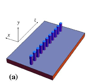
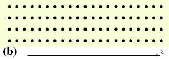
Other light guiding structures are nanopillar waveguides (NPWs) [10, 11], one-dimensional (1D) periodic arrangements of dielectric rods (see Fig. 1), where the guidance is realized by total internal reflection. They offer a variety of advantages over PCWs: The NPW geometry allows for more flexible arrangements than PCWs without substantially degrading the good transmission [12], including bendings and arbitrary alterations of the longitudinal periodicity. It has been shown that microcavities with high -factors can be formed by point defects in an otherwise periodic NPW due to the effect of multipole cancellation [13]. Furthermore, the NPWs allow for easy change of the pillar arrangement from periodic to quasiperiodic or deterministically aperiodic (DA), as recently proposed by us [14]. It has been shown that such DA NPWs support resonant modes which retain a high -factor and have a spatial radiation loss profile in favor of the coaxial direction (i.e. direction of periodicity or quasi-periodicity). These modes are intermediate between guided modes in periodic NPWs and localized microcavity modes, as is characteristic for non-periodic geometries.
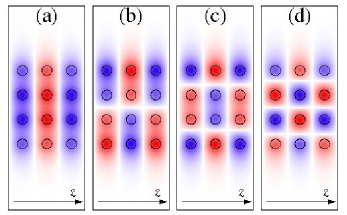
Another distinct advantage of NPWs is the possibility to create quasi-1D, i.e. multiple-row coupled NPWs (Fig. 1b) [10, 11]. The modes of the waveguide are then split, forming a clear supermode structure (see Fig. 3). By varying the inter-row spacing and lateral displacement, one can vary the coupling strength arbitrarily, which is very difficult in PCWs. What is more, it was shown that the supermodes can be easily excited selectively by placing the coherently emitting dipoles according to the spatial mode configuration [10].
In this paper we propose to use such a coupled NPW as a multimode laser cavity, when fabricated from a laser-active material. We investigate the possibility of switchable lasing mode selection in such devices. In this setup a continuous pumping source drives the occupation inversion in the active medium and, hence, the laser action. The mode selection among several pre-existing modes of an unaltered NPW device is then achieved by an additional optical pulse applied at the onset of the lasing action, using a spatial pulse intensity profile corresponding to the mode to be selected (optical injection seeding [15]). This is an alternative to the known concept of tunable lasers where the resonator itself is modified, e.g. by thermal, electrooptical (using liquid crystals) or micromechanical means [16, 17, 18, 19] to tune a given mode to have the desired frequency. One of the advantages may be that modes selected by injection seeding can be better pre-engineered to meet the desired fundamental (e.g., cavity QED) or application purposes [10].
The paper is organized as follows. Section 2 introduces the geometry and resonant mode structure of the coupled NPWs under study as well as the model of a four-level laser-active medium. In Section 3 we explain the injection seeding mechanism and discuss the numerical simulation of selective lasing. Section 4 summarizes the results.
2. Structures and laser model
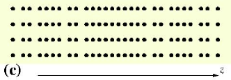
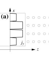
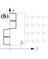
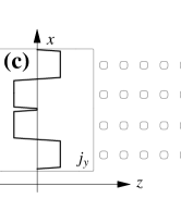
We consider a coupled four-row periodic NPW (see Fig. 1b), as described in Ref. [10]. The modes in question are shown in Fig. 3. They are supermodes formed by splitting of the first band edge resonance, resulting from the finite extension of the structure in the direction. The -factor is the strongest for these modes, which means that they dominate the NPW spectrum in the region of interest. In addition, following the results in Ref. [14] we consider an analogous four-row NPW based on a fractal Cantor structure (Fig. 1c), which supports critically localized supermodes. One can notice that the latter structure has two kinds of interpillar distances (short and long ) alternating in a non-periodic manner according to a procedure similar to the triadic Cantor set formation. For details on the construction procedure we refer the reader to Ref. [14]. Note that it is just one example of fractal structures; for more possibilities the reader is referred to Ref. [20] and references therein. In our numerical realization of NPWs we have used the following parameter values: The interpillar distances were taken to be , (the latter also used for periodic structures) and the inter-row spacing . The nanopillars with the radius and dielectric constant were placed in air (). The model is fully scalable [21] with the length scale and simultaneously with the frequency scale . For the explicit computations we used =500 nm.
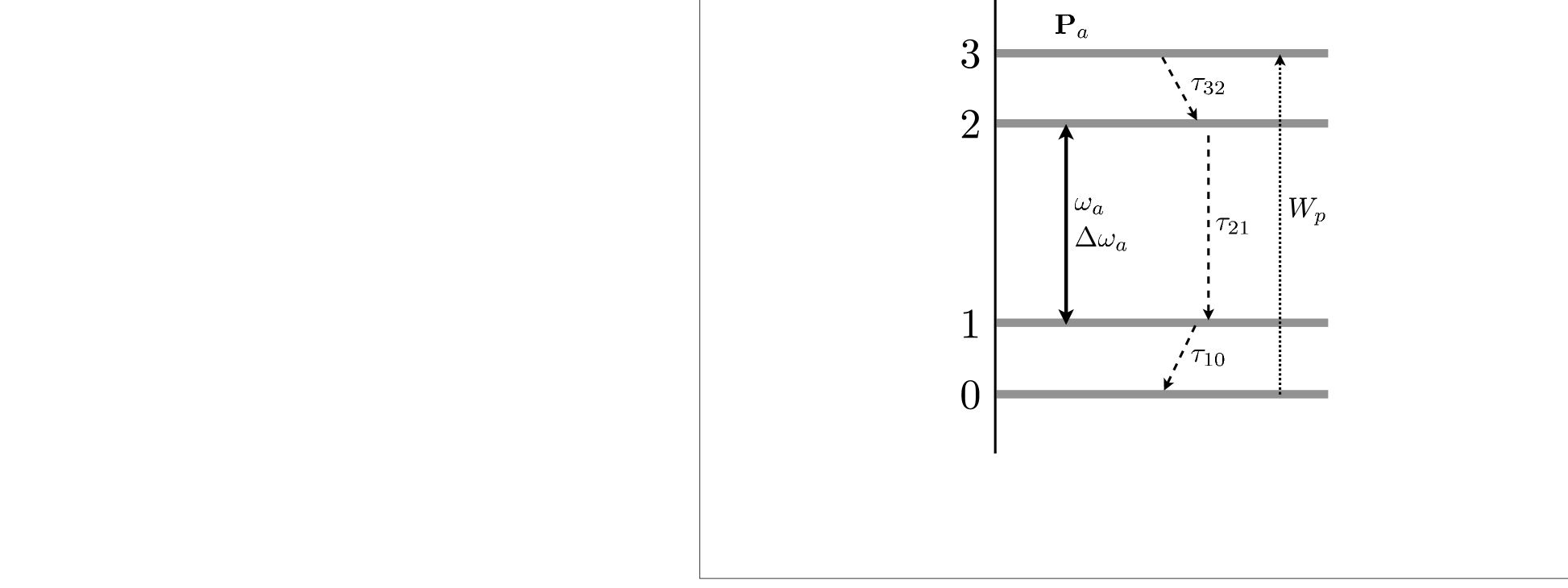
In order to model the gain in NPWs, we consider the semiclassical four-level laser model with external (e.g., electrical) pumping [22, 23] (Fig. 3). The lifetimes , and characterize non-radiative transitions between corresponding levels. Between the levels 2 and 1 there is also a radiative transition, the lasing transition, with frequency and radiative linewidth . In order to achieve population inversion, the lifetimes are taken so that . The population dynamics is controlled by the standard rate equations,
| (1) | |||||
| (2) | |||||
| (3) | |||||
| (4) |
Here the external pumpimg is modeled by the phenomenological pumping rate , which transfers electrons from the ground level to the uppermost level [22, 23]. The macroscopic polarization of the medium is governed in each spatial point by the equation of motion,
| (5) |
where is the population inversion, and the coefficient describes the coupling of to the electric field produced by stimulated photon emission. It is known to be [22, 24]. The electromagnetic fields are governed by the usual Maxwell equations,
| (6) |
We solve the system of equations (1-6) by the finite-difference time-domain method [25] with auxiliary differential equations (FDTD-ADE), e.g., as described in [22, 23]. The external current density is introduced in Eq. (6) as a technical tool within the FDTD method to excite the electromagnetic fields in the system (see Section 3). For the dielectric medium at hand is assumed to be Gaussian pulses of oscillating point dipole sources throughout this paper,
| (7) |
For the explicit FDTD solutions the nanopilars were assumed to extend infinitely in the third dimension (-axis), and TM polarization was considered, so that the electric field has only a -component, . To model an open system, perfectly matched layer (PML) boundary conditions were used [25]. The computational domain of size was discretized with 16 mesh points within the unit length . The time step is connected to the spatial mesh size to assure stability and was taken to be , i.e. for =500 nm. The four-level model parameters were chosen as , , and the total numer of laser-active atoms was taken to be per computation cell, as used in [24].
3. Injection seeding and selective lasing
As a microlaser device with injection seeding we consider a periodic or Cantor NPW (as in Fig. 1) coupled to a terminal through which the seeding signal is injected. The terminal is a slab wavewaveguide which is coaxially aligned with the NPW and extends out to the PML boundary of our system.
The externally pumped laser-active medium [Eqs. (1)-(4)] is placed in the pillars of all four rows of the central 10-pillar group (Cantor) or the 7 centermost pillars (periodic) of the NPW. This is done to maximize coupling between the active medium and the main localization region of the lasing modes; in the periodic case, it also helps to reduce the influence of second-order Fabry-Pérot modes.
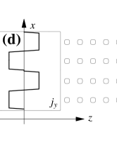
The seeding signal is excited by four actuators, i.e., linear groups of point dipole sources, modeled by Eq. (7) placed at the outer end of the terminal (next to the PML boundary) and aligned perpendicularly to the waveguide. Each of the actuators emits a single, short Gaussian pulse (7) with carrier frequency at or near and with a half-width duration . The relative phases and amplitudes of the actuators were taken to produce four different electric field profiles as shown in Fig. 4 so as to excite the four different-order transverse modes in the slab waveguide and in the NPW as shown in Fig. 3. Since the mode selection is based on the coherent light emission from the externally pumped medium stimulated by the seeding field, the mode selection process is phase sensitive [26, 15], that is, e.g. the modes of Fig. 3 can be distinguished, because they differ in the phase distribution but have essentially the same spatial intensity distribution. However, the selectivity may degrade, if the seeding signal induced by the actuators is not a waveguide eigenmode, so that several modes are excited in the waveguide while the signal propagates from the terminal to the laser-active region.
The mode selectivity is influenced by three major factors, (1) the precise time at which the Gaussian seeding signal is applied relative to the switch-on time of the pumping power; (2) random noise, generated, e.g., by spontaneous emission during the selection process, and (3) the -factors as well as the coupling strengths of the different modes to the lasing transition of the active material. Clearly, the seeding signal must be applied during the transient time interval, i.e. after the pumping power has been switched on, but before steady-state lasing has been reached, since otherwise the lasing would always be dominated by the one mode coupled most strongly to the lasing transition, independent of the seeding signal. This temporal dynamics and the influence of random noise will be analyzed in a forthcoming publication.
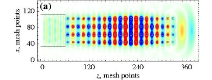
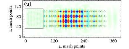
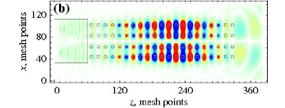
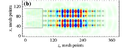
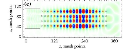
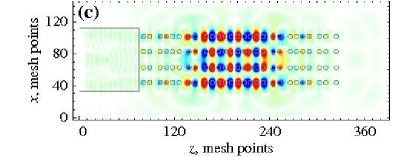
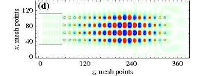
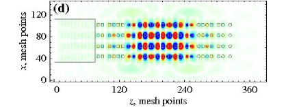
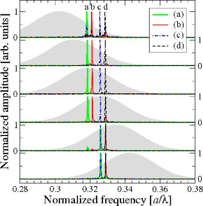
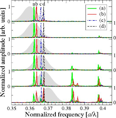
Here we focus on the mode selection in depencence of the -factors and coupling strengths of the modes. In Fig. 5 we show the spatial electric field distribution in the four-row NPW laser device described above at an instant of time long after the seeding signal has decayed and after the steady state has been reached. Here the frequency of the lasing transition was chosen so that the laser line overlaps with the mode eigenfrequencies. The symmetry of the selected lasing modes in Fig. 5 corresponds to that of the seeding signal shown in Fig. 3. It is seen that the lasing modes are the better localized inside the NPW structure (and thus their -factor is the higher) the higher their transverse order and, hence, the higher their frequency. Therefore, the higher-order modes are expected to be favored for lasing. This effect can be compensated for by different couplings of those modes to the lasing transition, as has been further analyzed in Fig. 6. It shows the lasing spectra (sharp coulored lines) in the steady state long after the seeding signal has decayed for various laser transition frequencies . The broad shaded areas depict the laser line of width centered at . When the mode eigenfrequencies lie slightly above (but still overlapping with the laser line), any of the four NPW modes can be selected by the appropriate seeding signal with the same symmetry, as seen in Fig. 6, upper four panels. We attribute this to the fact that in this case the low-frequency NPW modes have a stronger spectral overlap with the laser line than the high-frequency modes, thus compensating for the larger losses in the low-frequency modes. When the NPW mode frequencies are below the laser line (Fig. 6, lower two panels), the opposite effect occurs. In this case, for periodic NPWs (left panels) the two low-order modes cannot be selected by injection seeding, because of too low -factor and too weak coupling to the laser line. For Cantor NPWs the situation is somewhat better (right panels), presumably because in the Cantor structures the modes are better localized inside the NPW and have considerably higher -factors, which are less strongly dependent on the order of the modes, as seen in Fig. 5 and analyzed in Ref. [14]. It is also seen in Fig. 6 that in Cantor NPWs other modes than the four fundamental ones can participate in the lasing. Further analysis is needed to find out if this is due to their different (critical) spatial localization properties [14], which might prevent them from being subject to mode competition.
4. Conclusions and outlook
We have numerically investigated the possibility of selective lasing into each of the modes formed in coupled resonators [10]. Coupled nanopillar waveguides of both periodic and deterministically aperiodic fractal geometries have been used as a model. We have found that injection seeding can be used in order to achieve selective lasing with an externally pumped active medium. The seeding signal must be applied during the relatively short time period of the onset of lasing. The dependence of the mode selection on various parameters such as the lasing frequency has been investigated. We have shown that in fractal structures the modes are better localized than in the periodic case and yet show a good coupling to a coaxial terminal (compare graphs in Fig. 5) [14]. As a consequence, the lasing performance in such structures is expected to be greater, as conjectured by us earlier [14]. Note that the nanopillar-based structures in the wavelength range considered () are within the state-of-the-art fabrication possibilities, both in sandwich-like [6] and in membrane-like [18] geometry.
Based on the results obtained, we propose a new concept of switchable (rather than tunable) lasing in microstructures, when instead of changing the parameters of a single-mode cavity an inherently multiple-mode resonator is used, and one of the modes is deliberately selected for lasing. The modes can be pre-engineered to have the desired properties, and 1D deterministically aperiodic structures considered here offer broad possibilities for such engineering. However, the results presented here only form the first step towards such a concept. More detailed results and analyses will be presented in forthcoming publications.
Furthermore, in order to consistently develop the proposed concept of mode selection or switching, a theoretical description of lasing in a multimode resonator with arbitrary mode characteristics is required. Special attention needs to be given to interaction of the modes with different localization character, as well as modes having spatial and/or spectral overlap. Such a description has not yet been made, and is a subject for future studies.
This work was supported by the Deutsche Forschungsgemeinschaft (SPP 1113 and FOR 557).
References
- [1] J. D. Joannopouos, R. D. Meade, and J. N. Winn, Photonic crystals: Molding the Flow of Light, Princeton University Press (Princeton, 1995).
- [2] K. Sakoda, Optical Properties of Photonic Crystals, Springer (Berlin, 2001).
- [3] J.-M. Loutrioz et al., Photonic Crystals: Towards Nanoscale Photonic Devices, Springer (Berlin, 2005).
- [4] S. G. Johnson et al., Phys. Rev. B 60, 5751 (1999).
- [5] S. G. Johnson, P. R. Villeneuve, S. Fan and J. D. Joannoupoulos, Phys. Rev. B 62, 8212 (2000).
- [6] M. Tokushima, H. Yamada and Y. Arakawa, Appl. Phys. Lett. 84, 4298 (2004).
- [7] Y. Akahane, T. Asano, B.-S. Song and S. Noda, Nature 425, 944 (2003).
- [8] O. Painter et al., Science 284, 1819 (2004).
- [9] S. Noda, A. Chutinan and M. Imada, Nature 407, 608 (2000).
- [10] D. N. Chigrin, A. V. Lavrinenko and C. M. Sotomayor-Torres, Opt. Express 12, 617 (2004).
- [11] D. N. Chigrin. A. V. Lavrinenko and C. M. Sotomayor-Torres, Opt. Quantum Electron. 37, 331 (2005).
- [12] P.-G. Luan and K.-D. Chang, Opt. Express 14, 3263 (2006).
- [13] S. G. Johnson, S. Fan, A. Mekis and J. D. Joannopoulos, Appl. Phys. Lett. 78, 3388 (2001).
- [14] S. V. Zhukovsky, D. N. Chigrin and J. Kroha, J. Opt. Soc. Am. B 23, 2265 (2006).
- [15] W. Lee and W. R. Lempert, Appl. Opt. 42, 4320 (2003).
- [16] A. Figotin, Y. A. Godin and I. Vitebsky, Phys. Rev. B 57, 2841 (1998).
- [17] K. Yoshino et al., Appl. Phys. Lett. 75, 932 (1999).
- [18] W. Park and J.-B. Lee, Appl. Phys. Lett. 85, 4845 (2004).
- [19] E. P. Kosmidou, E. E. Kriezis and T. D. Tsiboukis, IEEE J. Quant. Electron. 41, 657 (2005).
- [20] S. V. Zhukovsky, A. V. Lavrinenko and S. V. Gaponenko, Europhys. Lett. 66, 455 (2004).
- [21] P. Bermel, E. Lidorikis, Y. Fink and J. D. Joannopoulos, Phys. Rev. E 73, 165125 (2006).
- [22] A. S. Nagra and R. A. York, IEEE Trans. Ant. Propag. 46, 334 (1998).
- [23] X. Jiang and C. M. Soukoulis, Phys. Rev. Lett. 85, 70 (2000).
- [24] S.-H. Chang and A. Taflove, Opt. Express 12, 3827 (2004).
- [25] A. V. Lavrinenko et al., Opt. Express 12, 234 (2004).
- [26] A. Siegman, Lasers, University Science Books, (Mill Valley, CA, 1986).