Vortex configurations and critical parameters in superconducting thin films containing antidot arrays: Nonlinear Ginzburg-Landau theory
Abstract
Using the non-linear Ginzburg-Landau (GL) theory, we obtain the possible vortex configurations in superconducting thin films containing a square lattice of antidots. The equilibrium structural phase diagram is constructed which gives the different ground-state vortex configurations as function of the size and periodicity of the antidots for a given effective GL parameter . Giant-vortex states, combination of giant- and multi-vortex states, as well as symmetry imposed vortex-antivortex states are found to be the ground state for particular geometrical parameters of the sample. The antidot occupation number is calculated as a function of related parameters and comparison with existing expressions for the saturation number and with experimental results is given. For a small radius of antidots a triangular vortex lattice is obtained, where some of the vortices are pinned by the antidots and some of them are located between them. Transition between the square pinned and triangular vortex lattices is given for different values of the applied field. The enhanced critical current at integer and rational matching fields is found, where the level of enhancement at given magnetic field directly depends on the vortex-occupation number of the antidots. For certain parameters of the antidot lattice and/or temperature the critical current is found to be larger for higher magnetic fields. Superconducting/normal phase boundary exhibits different regimes as antidots are made larger, and we transit from a plain superconducting film to a thin-wire superconducting network. Presented results are in good agreement with available experiments and suggest possible new experiments.
pacs:
74.20.De, 74.25.Dw, 74.78.Na, 74.25.HaI Introduction
Superconducting (SC) samples with periodic arrays of pinning sites have received much attention over the last decade. It is now well established that these artificial pinning centers (i) hold great potential for enhancing the critical parameters of the sample and (ii) give rise to different kinds of vortex behavior that is not observed in the presence of random pinning. In this respect, arrays of microholes (antidots) harada ; baert ; MoshPRB96 ; MoshPRB98 ; metl ; vanlook ; silha2 ; silha ; silha05 ; read ; grigor ; doria and submicron magnetic dots, Martin1 ; Martin2 ; mishko have been studied, as their presence in the SC film strongly modifies the vortex structure compared to the one in non-patterned films. abrikos ; abri_2
Direct imaging experiments, harada magnetization and transport measurements, baert ; MoshPRB96 ; MoshPRB98 ; metl and theoretical simulations ReiPRB97 ; ReiPRB98 ; ReiPRB01 ; ReiPRB011 ; zhu of vortex structures in samples with periodic pinning centers have shown that the vortices form highly ordered configurations at integer and at some fractional (n,p,q being integers) matching fields, where is the flux quantum, and is the area of the primitive cell of the artificial lattice. This remarkable variety of stabilized vortex lattices may even be broadened by multiple possible degeneracies. These commensurability effects between the pinning array and the vortex lattice are responsible for an enhanced pinning and consequently increased critical currents. Very recently Karapetrov et al. STM investigated vortex configurations in a single crystal superconducting heterostructures with an array of submicron normal metal islands by scanning tunneling microscopy. They observed the coexistence of strongly interacting multiquanta vortex lattice with interstitial Abrikosov vortices. Different vortex phase transitions are given, which occur when the number of magnetic flux quanta in the sample changes.
Motivated by those experimental studies on perforated superconductors, significant efforts have been made on the theoretical side as well. For example, extensive molecular dynamics simulations ReiPRB97 ; ReiPRB98 ; ReiPRB01 ; ReiPRB011 ; zhu in the London limit have been performed in an attempt to calculate the vortex structure and their dynamics in a periodic pinning potential. Although the general behavior of vortex lattices was accurately described, made approximations are valid only in certain range of parameters. Namely, in the London approach, vortices are considered as classical point-particles (with different models for their interaction) and the influence of the antidots is introduced through model hole potential, which in principle can never be generalized. Recently, Nordborg and Vinokur nord discussed in the detail interaction of vortices with an arbitrarily large cavity, but still within the London theory. This study was actually an extension of the work of Mkrtchyan and Shmidt, Mkrt who crudely estimated the maximum possible number of vortices trapped by a single insulating inclusion with radius as , where is the temperature dependent coherent length. For regular arrays of pinning centers the saturation number becomes due to the vortex-vortex interactions. DoriaPC The antidot-vortex interaction and the following maximal occupation number of each antidot appear to be crucial for many phenomena. For example, experiments on thin films with a lattice of holes showed a “localization transition” bezr : all vortices drop inside the holes when the coherence length becomes larger than the interhole spacing. In Ref. MoshPRB98 it was shown that the antidot size realizing the optimum pinning is actually field-dependent. The effective vortex-pinning potential and saturation number of the pinning sites for different temperature and applied fields were recently investigated experimentally by means of -susceptibility measurements, for superconducting films with an array of antidots silha2 ; silha and for the case of not fully perforated holes (i.e. blind holes). read
Most of the experiments on perforated superconducting films are carried out in the effective type-II limit (, being the thickness of the superconducting film and the magnetic penetration depth). In this regime, the vortices act like charged point particles and their interaction with periodic pinning potential can be described using molecular dynamic simulations. ReiPRB97 ; ReiPRB98 ; ReiPRB01 ; ReiPRB011 . However, the overlap of vortex cores (with size ), and the exact shape of the inter-vortex interaction (depending on the superconducting material properties reflected through ), may significantly modify the vortex structures and consequently the critical current when this criteria is no longer satisfied.
Besides, the vortex-pinning and the critical current enhancement, higher critical field () near an open circular hole in a thin film (the so-called “surface superconductivity”) has been predicted theoretically BuzdinPRB93 and confirmed experimentally. bezrJLTP Cusps in the boundary were observed, which occurs when the number of vortices which nucleate inside the hole increases by one, similarly to the known Little-Parks effect. The ratio between the critical fields in perforated samples was estimated in limiting cases: when (or ) and when .
In this work superconducting films with square arrays of antidots are treated within the phenomenological Ginzburg-Landau theory. This approach considers vortices as extended objects and no approximations have to be made on e.g. the vortex-vortex interaction and/or the vortex-antidot interaction. In Sec. II, the details of our numerical formalism are given. Sec. III deals with vortex lattices in perforated films in homogeneous magnetic field, with emphasis on the number of pinned and interstitial vortices as function of the antidot-size and interhole distance. In case of weak pinning potentials, i.e. small size anti-dots, we discuss the triangle to square vortex lattice transition in Sec. IV. In Sec. V, we address the behavior of critical current in the sample as function of the applied field, for different geometrical parameters, and temperature. The dependence of the critical field on temperature, and different regimes in the phase diagram are discussed in Sec. VI for different antidot-size. All presented findings are then summarized in Sec. VII.
II Theoretical formalism
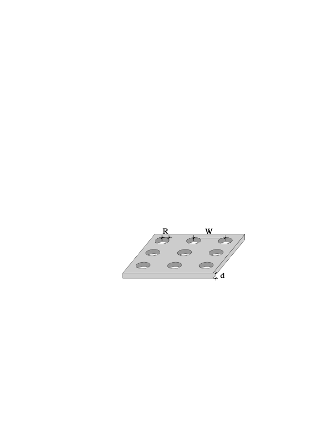
In this work, we consider a thin superconducting film (of thickness ) with a square array of holes (radius , period ) immersed in an insulating media in the presence of a perpendicular uniform applied field (see Fig. 1). To describe the superconducting state of the sample we solve the coupled nonlinear GL equations, which are written in dimensionless units in the following form SchPRL98 ; SchPRB98 :
| (1) |
| (2) |
We measure the distance in units of the coherence length , the vector potential in , the magnetic field in , and the order parameter in with , being the GL coefficients.
The magnitude of the applied magnetic field is determined by the number of flux quanta Gcm2 piercing through the rectangular simulation area , with and and are integers. At the superconductor/insulator interface we impose the boundary condition corresponding to zero normal component of the superconducting current. The periodic boundary conditions for and (simulating the periodicity of both superconducting film and antidot lattice) have the form DoriaBC
| (3) |
| (4) |
where () are lattice vectors, and is the gauge potential. These boundary conditions imply that , are invariant under lattice translations combined with specific gauge transformations . Other quantities, such as the magnetic field, the current or the order parameter density are periodic. We use the Landau gauge for the external vector potential and , , with , being constants. mishko Without antidot lattice, when the film is invariant under infinitely small translations, the free energy does not depend on , . The vortex lattice is only shifted relative to the simulation region when and are varied. This is not the case for an antidot lattice, when the change of these parameters leads to a displacement of the vortex lattice relative to the holes, leading to a variation of the free energy. In general, one has to minimize the free energy with respect to , . It can be shown that such a minimization gives a zero current when averaged over the cell area. We find that for a supercell having one hole, the optimal values are given by and that for the supercell with holes the choice provides the minimum free energy.
We solved the system of Eqs. (1,2) self-consistently using the link variable approach Kato in a finite-difference representation of the order parameter and the vector potential using a uniform cartesian space grid . The first GL equation is solved with a Gauss-Seidel iteration procedure. SchPRL98 The vector potential is then obtained with the fast Fourier transform technique. The temperature is indirectly included in the calculation through the temperature dependence of the coherence length and penetration depth , where is the critical temperature at zero magnetic field.
III Vortex lattices - influence of geometrical parameters
We first consider a supercell containing four holes () of radius , with lattice period (see Fig. 1). Although our approach is valid for any integer number of flux-quanta piercing through the simulation region, we will restrict ourselves here to the so-called (integer and fractional) matching vorticities.
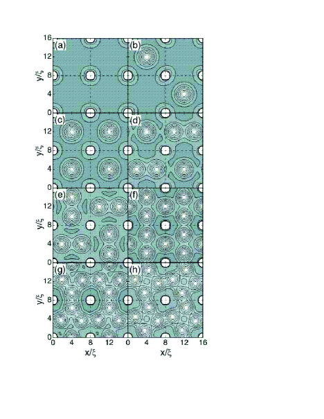
Figure 2 shows contour plots of of the vortex lattice in case of antidots of radius and interhole distance for different matching fields . The film thickness is and the effective GL parameter . At the first matching field all vortices are trapped in the antidots [Fig. 2(a)]. Because of their small radius, each antidot is able to pin only one vortex, and additional vortices localize at interstitial sites when [see Fig. 2(b) for ]. At the second matching field [Fig. 2(c)] vortices occupy all interstitial sites, forming again a square lattice. For , [Fig. 2(d)] vortices form an ordered lattice with an additional vortex at every other interstice, added to the case. Note that the size of the vortex cores at neighboring interstitial sites differs: two vortices at the same interstice strongly interact and effectively bound each others core-areas, while the neighboring single interstitial vortex does not suffer from any lack of space resulting in its larger core. At the third matching field (three vortices per unit cell) two interstitial vortices in adjacent cells alternate in position [see Fig. 2(e)], preserving the two-fold symmetry, but the vortex unit cell is 4 times the antidot lattice unit cell. At [Fig. 2(f)] we observe the first evidence of the competition between the Abrikosov vortex lattice (characteristic for thin film superconductors) and the symmetry of the pinning lattice, as vortices (including pinned ones) form a slightly deformed hexagonal lattice. Notice that for [Fig. 2(g)] the number of vortices per antidot unit cell is and the vortex lattice unit cell is twice the antidot unit cell. At the fifth matching field [Fig. 2(h)] the dense packing of vortices and their consequent strong interaction with the antidot lattice result in the restoration of the square lattice symmetry but the vortex lattice is tilted over with respect to the antidot lattice. Our results are in excellent agreement with the experiment of Ref. harada and previous molecular dynamics simulations,ReiPRB98 in certain parameter range. Namely, the vortex configurations are mainly determined by the pinning force of each antidot, and the vortex-vortex interaction. The latter is very dependent on the density of vortex packing, as the known expressions for the vortex-vortex interaction do not take into account possible overlap of vortex cores. On the other hand, the antidot-vortex pinning potential is determined by the antidot-size and the period of the antidot-lattice. Our approach takes all these aspects into account and their influence will be discussed in the remainder of this paper.
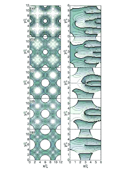
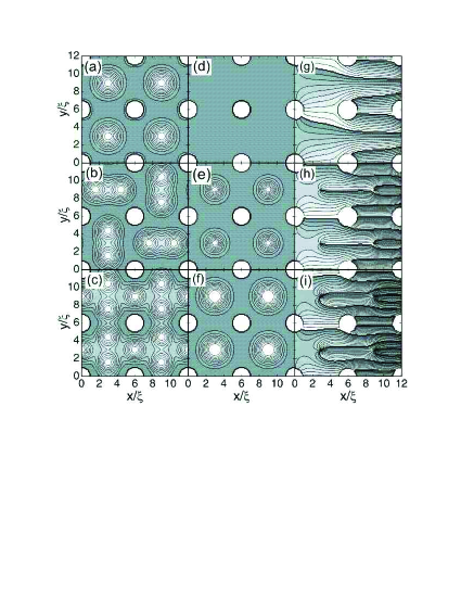

As shown in Fig. 2, for small hole radii, each antidot pins only one vortex (the hole occupation number , the number of vortices sitting in the holes, equals 1), and the remaining vortices reside between the holes. One expects that, for larger hole radius , vortex configurations with multi-quanta vortices in each hole can become energetically preferable. STM ; BuzdinPRB93 Figure 3 shows the contour plots of the Cooper-pair density at the sixth matching field for different antidot radii. The antidot lattice period is , the thickness is and . The number of vortices captured by each hole changes from one for [Fig. 3(a)] to five for [Fig. 3(e)]. The vortex arrangement outside the holes is determined not only by their mutual interaction, but also by the attraction with the antidots and the repulsion by their pinned vortices. For small radius a multivortex structure is found at the interstitial sites, as apparent from Fig. 3(a,b) (see also Fig. 2). By further increasing some of the vortices enter the holes and the remaining vortices are strongly caged between the antidots, resulting in the formation of giant vortices [Fig. 3(d)] and symmetry imposed vortex-antivortex pairs PRL06 [Fig. 3(c)]. This is apparent from the contour plot of the phase of the order parameter (right column of Fig. 3).
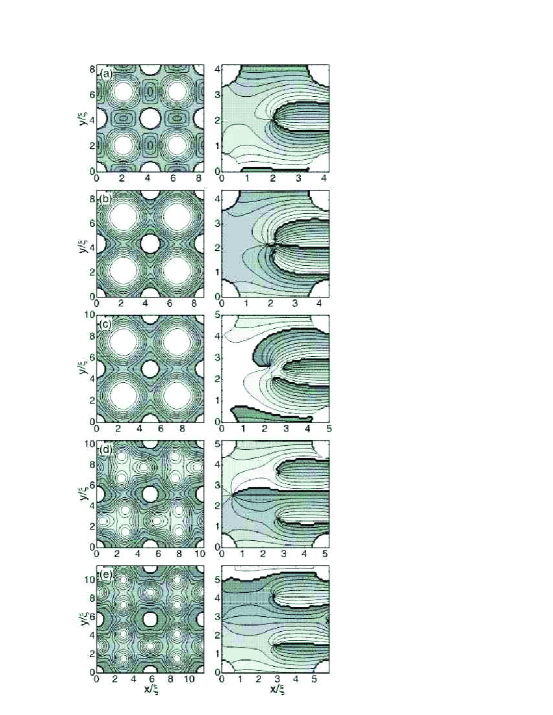
Similar behavior can be achieved if the hole-size is kept the same, but the period of the hole lattice is decreased, as illustrated in Fig. 4. For small period the interstitial vortices form a giant vortices [Fig. 4(a)] because of the strong interaction with the pinned vortices in the antidots. With increasing one extra vortex is depinned and, due to the symmetry of the sample, vortex-antivortex pair with four vortices and one antivortex is formed in each interstitial site [Fig. 4(b)]. Further increase of leads to a triangular vortex structure at the interstitial sides with chosen orientation that minimizes the energy between neighboring cells [Figs. 4(c-e)].
It is well known that the vortex-vortex interaction changes sing at the point . For , vortices repel each other while for they attract. To see how this attractive interaction modifies the different vortex lattice configurations we consider a sample with small . Fig. 5 shows the contour plots of the Cooper-pair density for (type-II regime) and (type-I regime) for the second, third and fourth matching fields. For the given parameters of the sample and for each hole pins one vortex and the remaining vortices sit at interstitial sites [Figs. 5(a-c)]. The occupation number of each hole is increased to two in the type-I sample [see Figs. 5(d-i)]) due to the enhanced expulsion of the magnetic field by the superconductor. Moreover, because of the attractive interaction between vortices, giant vortices become energetically more favorable contrary to the case for . Due to the instabilities of vortex states, which is common for type-I superconductors, variety of metastable vortex structures can be found (see also Ref. PC06 ). As an example we show in Fig. 6 different metastable vortex states of the sample in Fig. 5 for . The free energies of those states are: -0.3268 (a), -0.2823 (b), -0.2787 (c) and -0.2755 (d). The ground state free energy [Fig. 5(f,i)] is . Notice that because of the attractive interaction a giant vortex state is always favored.
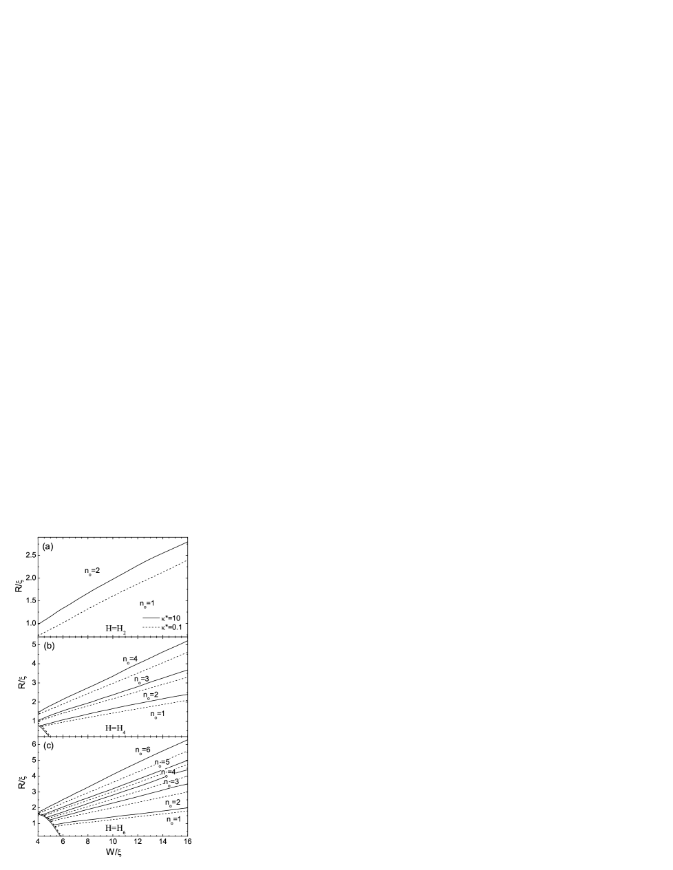
To summarise the above findings, we constructed the equilibrium vortex phase diagram, which shows the dependence of antidot-occupation number on and for two values of , at the second, fourth and sixth matching fields (Fig. 7). The ground- and metastable states are determined in our calculation by comparing the energy of all stable vortex states found when starting from different randomly generated initial conditions. The procedure of finding the free energy of the different metastable states was similar to that used for the case of mesoscopic superconducting disks. SchPRL98 ; SchPRB98 It should be noted, that an energetically unfavorable state remain stable in the wide range of variation of and . Therefore, the transitions between the vortex states with different occupation numbers are of first-order. It is seen from this figure that increases as the applied field is increased, which is in agreement with experimental results and theoretical predictions. baert ; doria ; STM ; BuzdinPRB93 With decreasing the threshold hole-radius for capturing another vortex decreases due to the smaller pinned vortex-interstitial vortex repulsion.
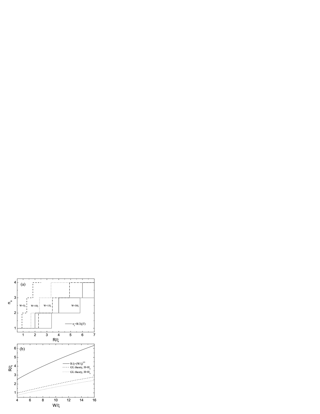
Let us compare our numerical results for the hole-occupation number with existing theoretical predictions. The saturation number ( for larger fields) is usually estimated as . Mkrt Fig. 8(a) shows the hole occupation number obtained from this expression and the one from our GL calculation for different period of the antidots. It is seen from this figure that this expression underestimates for small period (dashed and dotted curves). This is due to the fact that the last expression does not account for the interaction between vortices sitting at different holes. For larger period the occupation number is smaller in our calculation for a given radius of the holes (gray curve). A more accurate analysis was presented by Buzdin BuzdinPRB93 for bulk superconductors within the London approach. However, his estimation of the critical hole radius (for ) and (for ) corresponding to the transition from single flux-quantum to two flux-quanta captured by the hole, differ from our numerically exact results, i.e., the magnitude of the critical hole radius is largely overestimated in Ref. BuzdinPRB93 for both small and large period [see Fig. 8(b)].
The maximum number of flux quanta that can be trapped in a pinning center in a thin superconducting film was recently studied experimentally using scanning Hall probe microscopy grigor and ac susceptibility measurements. silha In the latter case the saturation number was obtained from the transition to different dynamic regimes, as the interstitial vortices have higher mobility than those pinned by the antidots. They studied thin Pb films containing a square antidot array of period m. The antidots had circular (square) shape with radius nm (size m), the film thickness was nm (nm) and the coherence length at zero temperature was estimated nm (nm) in Ref. grigor (Ref. silha ). Let us first discuss the results for the sample of Ref. grigor , where the experimentally obtained saturation number was =2 at . Fig. 9(a) shows the antidot occupation number as a function of temperature for different applied matching fields. At small applied fields () the occupation number is equal to two, which is in agreement with the experimentally obtained . With increasing applied field one more vortex is trapped by the holes, i.e. , which is now larger than the experimental value. At higher temperatures , again becomes equal to two. In this case one would estimate the saturation number from Mkrt to be for and for . We found the occupation number equal to only for the second matching field at the temperature range . The estimation of Buzdin BuzdinPRB93 for the critical hole radius , where the transition from to occurs, gives the temperature range . We found this transition at this temperature only for the second matching field. For larger fields the occupation number is always larger than unity. The giant vortex state is found only at for and the vortex-antivortex state is formed at for the temperatures .
Up to now we use the temperature dependence for the coherence length and penetration depth as shown at the end of Sec. II which is obtained from the BCS theory tinkham and is valid near . In this case the GL parameter is temperature independent. In recent experiments on Pb arrays of nanowires arrays Stenuit et al. wire found that the following temperature dependence of the coherence length and penetration depth , which leads to a temperature dependence of the GL parameter , agrees better with experiment. Here and . These expressions are obtained from the two-fluid model. We calculated the hole occupation number using the above temperature dependencies, which is shown in the inset of Fig. 9(a). It is seen from this figure that the transition from to -1 occurs now at higher temperatures, but the results are qualitatively similar with the earlier results.

Fig. 9(b) shows the occupation number as a function of temperature for different matching fields for the sample of Ref. silha . The experimentally obtained saturation number was for temperatures . Our calculations give the same occupation number for this range of temperatures but only for fields . The expression for the saturation number gives in this case . At larger fields the occupation number increases, but still there will be interstitial vortices in the sample. STM These interstitial vortices lead to a larger dissipation in the sample which was used as the criterium for the determination of the saturation number . But our calculations show that the appearance of interstitial vortices does not indicate the saturation of trapped vortices.
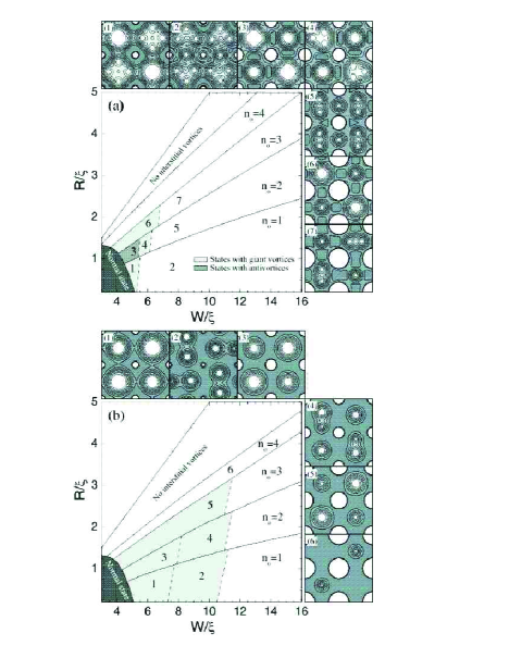
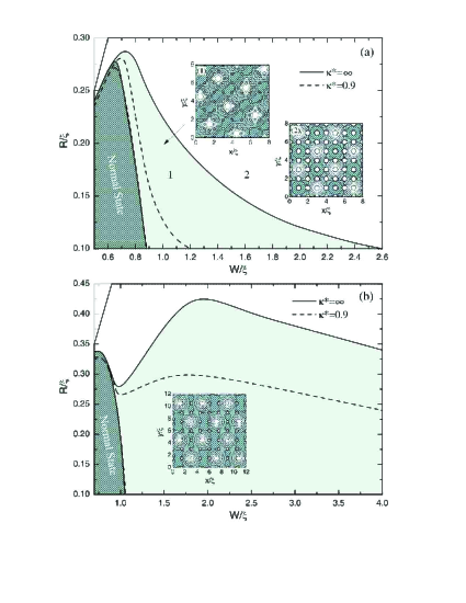
We have shown in our recent paper PRL06 that a rich variety of ordered vortex structures: a combination of giant vortices with mltivortices and vortex-antivortex pairs are found in perforated superconducting samples for fractional matching fields. Here we consider the dependence of these vortex states on the effective GL parameter . As an example we constructed the equilibrium vortex phase diagram for rational matching field (i.e. 4.5 flux quanta per antidot) as a function of and , and for [Fig. 10(a)] and [Fig. 10(b)]. In type-II regime [Fig. 10(a)], for larger period the vortex configuration always consists of individual vortices, except for flux lines pinned by each hole. One extra vortex per two holes is shared between the adjacent cells (insets 2, 5) or situated in every other cell (inset 7). With decreasing , the interstitial vortices become strongly caged between the neighboring antidots, resulting in the distortion of the individual-vortex lattice. In this case, the -th matching field becomes larger than the second critical field for . But the superconducting state in perforated films still survives due to enhanced superconductivity in close proximity around the holes (due to surface superconductivity). If the radius of the holes is then increased, individual vortices captured at interstitial sites can merge for to a giant vortex [(region 1 in Fig. 10(a)]. This transition does not show any hysteretic behavior and is, therefore, of second order (similarly to the case for mesoscopic disks SchPRL98 ). The creation of these giant vortex states is favored because of the repulsion of the vortices by the supercurrents around the holes (and consequent compression of vortices in the central part of the interstitial regions).
The influence of caging depends on the number of confined vortices; the combinations of giant- and multi-vortices may be formed in the interstitial sites (insets 1, 4 and 6). For interstitial vorticity 3, a vortex-antivortex pair may nucleate, so that local vortex structure conforms with the square symmetry of the pinning lattice [see inset (3) in Fig. 10(a) and Ref. PRL06 ].
Fig. 10(b) shows the ground-state phase diagram found for . Compared to Fig. 10(a), the threshold antidot-radius for capturing another vortex decreases due to the enhanced screening of the applied field. Due to the attractive vortex-vortex interaction in type-I samples, giant-vortex states become energetically favorable at the interstitial sites and spread over the majority of the phase diagram (light gray areas). For a dense antidot lattice, giant vortices with different vorticity are found in adjacent cells [ and (inset 1), and and (inset 3)]. Contrary to the type-II case, these giant vortices can split to smaller giant vortices for larger spacing of antidots. They exhibit single-vortex behavior, forming the lattice of 2-quanta and single-quanta vortices (insets 2 and 4). Such new quasi-Abrikosov lattices of giant-vortices result from the competition of vortex-vortex attraction and imposed square symmetry of pinning. At the same time, these competing interactions cause the complete disappearance of the vortex-antivortex structures as found in type-II samples.
IV Triangular to square vortex lattice transition in the presence of a square antidot lattice
It is well known that the regular triangular vortex lattice has the lowest energy in superconductors with no pinning.abri_2 As we have shown above the square lattice of pinning sites impose its own symmetry on the vortex structure. If the vortex-pinning strength in a periodic square array is reduced, the vortex-vortex repulsion starts to dominate over the pinning force and the triangular lattice is recovered. Transition between these phases was recently studied in Ref. pogosov as a function of the amplitude of the vortex-pinning site interaction and the characteristic length scale of this interaction within the London theory (i.e. ). They showed that the transition between triangular and square vortex lattice occurs for increasing strength of the pinning potential in the case of small values of pinning potential length scale. In Ref. pogosov a model periodic pinning potential was introduced, the parameters of which are difficult to relate to any growth parameters of the sample.
To circumvent the latter problem we studied the case of weak pinning potential by introducing small antidots. Thus in order to decrease the pinning force in our calculations we just reduced the radius of the antidots for a given period of antidot lattice . Calculations are done for a unit cell () with grid points . Fig. 11 shows the phase diagram: the transition between the pinned (white region) and triangular (light gray region) vortex lattice as a function of the radius and period of antidots for the applied fields (a) and (b). Let us first discuss the results for . When the pinning strength is small (small ), it is energetically favorable to form a triangular lattice, where vortices are located between the holes [left inset in Fig. 11(a)]. For larger radius of the holes a square vortex lattice becomes the ground state [right inset in Fig. 11(a)]. The critical radius of the holes to pin the vortices decreases with increasing period, contrary to the one corresponding to the case of two-flux quanta captured by the holes [see Fig. 8(b)]. If we decrease the GL parameter the transition between pinned and triangular vortex lattices decreases (dashed curves in Fig. 11) due to the short range interaction between the vortices.
In Ref. pogosov the phase diagram for the transition between the triangular and square vortex lattice was found to be the same for all submatching fields not exceeding , except and . Contrary to this results our calculations give a different phase diagram for different fractional matching fields. As an example, we show in Fig. 11(b) the transition lines between triangular and square pinned vortex configurations for . The triangular vortex lattice is formed where some of the vortices are pinned and some of them are located between the antidots [see the inset of Fig. 11(b)]. For this value of the field the triangular vortex lattice is found for larger values of the period and radius of the antidots.
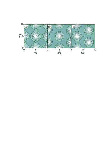
For the fields and the pinned vortex lattice has a square symmetry. An intermediate vortex configuration for these fields was obtained in Ref. pogosov where vortices in odd rows of pinning centers are depinned and are located between the pinning sites forming a kind of triangular lattice. Our calculations show that such vortex configurations can be found only as a metastable state and for relatively larger values of the period (). To make this more clear we plot in Fig. 12 the ground state (a) and metastable (b,c) vortex configurations at the first matching field. In addition to the triangular vortex state given in Ref. pogosov [see Fig. 12(b)] another triangular vortex state is found, where all the vortices are located in the interstitial region [Fig. 12(c)].
V Critical current of patterned SC films
In the previous sections we showed that vortex configurations that are commensurate with the periodic arrays of antidots exhibits well-defined matching phenomena, which leads to pronounced peaks in the critical current (see for example Ref. MoshPRB98 ). However, the stability of these vortex states strongly depend on the parameters of the sample. For example, a multi-quanta vortex state become energetically favorable for large radius of the holes, while small holes can capture only a single vortex. The additional vortices located in interstitial sites reduces the critical current considerably. Therefore, we first investigate the critical current of our sample as a function of the relevant antidot parameters.
The first step to calculate the critical current is to accurately determine the vortex ground state for given applied magnetic field, in a manner described in previous section. Then the applied current in the direction is simulated by adding a constant to the existing vector potential of the applied external field. mishko With increasing we find a critical value of such that a stationary solution to Eqs. (1-2) cannot be found since a number of vortices is driven in motion by the Lorentz force. The current in the sample corresponding to the given value of is obtained after integration of the -component of the induced supercurrents in the -cross-section. The maximal achievable value of denotes the critical current .
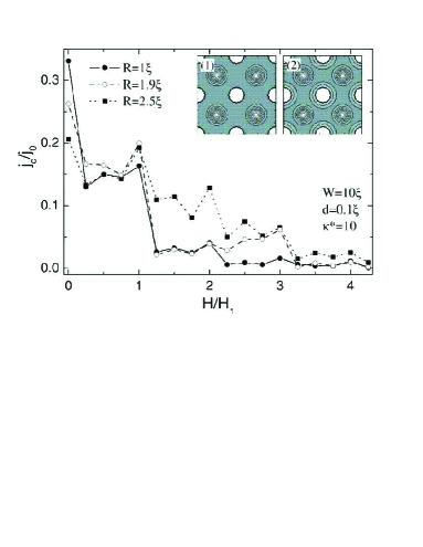
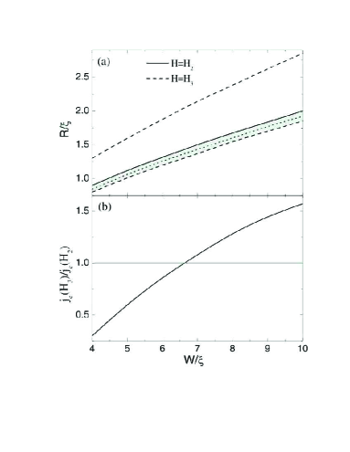
Fig. 13 shows the critical current density (in units of ) as a function of applied magnetic field (normalized to the first matching field ) for different values of the antidot radius for fixed value of the antidot lattice period . For small radius (solid circles), where only one vortex can be pinned by the hole, the peaks at the matching fields decrease with increasing applied field. The opposite behavior is found when there is a caging effect, golibEPL i.e. , which e.g. is found for radius (open circles) for and . This effect occurs when there are the same number of interstitial vortices but the number of pinned ones are different at the different matching fields. In this case the interstitial vortices feel a stronger repulsive interaction when there are a larger number of pinned vortices. As is shown in Fig. 13 (open circles), a higher critical current is found for the third matching field, when a double vortex occupies each hole and a single one is located at the interstitial, than for the second matching, with one vortex in each hole and a single interstitial vortex (see the insets of Fig. 13). This effect disappears with further increasing the radius due to the different occupation number , i.e. no interstitial vortices at .
In order to show the range of radius and period of antidots, where this caging effect is active, we constructed a phase diagram for and , shown in Fig. 14(a). The shadowed area indicates the vortex state with a single interstitial vortex for both (solid line) and (dashed curves). Fig. 14(b) shows the ratio as a function of period . The critical radius is taken from the middle of the region (dotted curve). It is seen from this figure that, although we have the same vortex structure for all values of the period , the enhancement of is found only for . For small period the pinned vortices at suppresses superconductivity around the holes and interstitial vortices are easily set into motion, reducing the critical current.
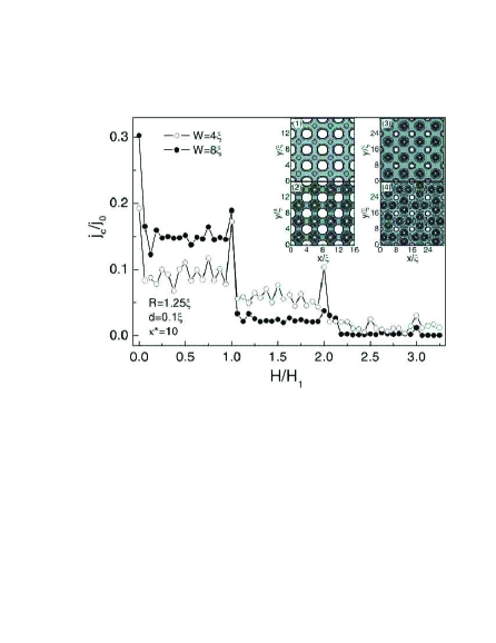
Fig. 15 shows the critical current density as a function of the field for two values of the period: (open circles) and (solid circles) at . As we showed above, the curve shows pronounced maxima at integer fields , and and at some of the fractional matching fields. However, while the qualitative behavior of in Fig. 15 is as expected, its quantitative behavior reveals a counterintuitive phenomenon. Namely, one expects higher critical current in the sample with larger interhole distance, simply due to the presence of more superconducting material. Indeed, that is the case for , where the superconductor is able to compress all flux lines in the holes. However, for higher magnetic fields, the critical current drops sharply immediately after the first matching field , which is related to the appearance of interstitial vortices. On the other hand, the smaller interhole distance affect the hole occupation number (see Fig. 7), and the additional vortices after are still captured by the holes (as illustrated by Cooper-pair density plots in the inset of Fig. 15). Consequently, the critical current in this case is larger for smaller periodicity. Note that even for smaller periodicity a sharp drop in is observed for , as every additional vortex disturbs the stability of the vortex lattice. Even at , although all vortices are captured by the holes, the critical current is lower, due to a stronger suppression of the order parameter around the holes compared to the case. The height of the matching peaks is decreasing with further increasing field (due to the presence of interstitial vortices), which agrees with experiment (see Ref. MoshPRB98 ), and these peaks strongly diminish for higher fields as the vortex-flow overwhelms the pinning potential.
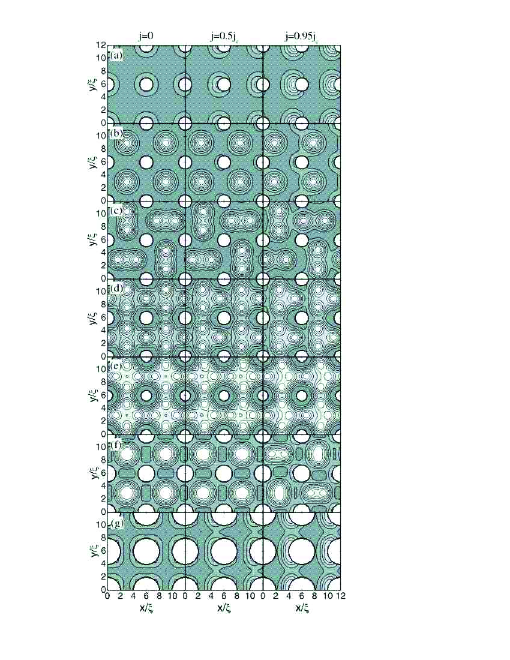
When we apply a dc current into the superconductor the vortex lattice is distorted before the vortices start moving. To illustrate this phenomenon, we plot in Fig. 16 the Cooper pair density of the superconducting film at the applied currents (in direction) (first column), (second column) (third column) for different matching fields. At the first [Fig. 16(a)] and second [Fig. 16(b)] matching fields all the vortices are displaced over the same distance, conserving the square symmetry in the lattice of vortices. At larger fields, when there is a large number of interstitial vortices [Fig. 16(c-e)], the vortex configuration is changed by the current and some of the vortices are jammed at the interstitial sites. If we initially have giant vortices [Fig. 16(f)] they can be split into multivortices with increasing . Our calculations also show that there is no transition from the multivortex state to the giant vortex state when we increase the applied current, and the occupation number of the antidots is found to be independent of .
Another interesting feature following from the displacement is found for fractional matching fields. For example, Fig. 2(d) shows alternating two-vortex - single vortex structure at , where applying small current in -direction can shift the excess-vortex from one interstitial site to another. Note that resulting state has identical configuration and energy as the previous one. In order to estimate the energy barrier between these two vortex states we performed calculations for a superconducting film of thickness nm with an array of antidots with period m, radius m, at temperature . We take nm and nm, which are typical values for Pb thin films. We found an energy barrier of meV, which is significantly higher than the thermal activation energy at this temperature (meV), but still low enough for successful switching by a relatively weak current. Moreover, when an current is applied to the sample, the vortex can shift back and forth between the adjacent cells, resulting in resonant dissipation.
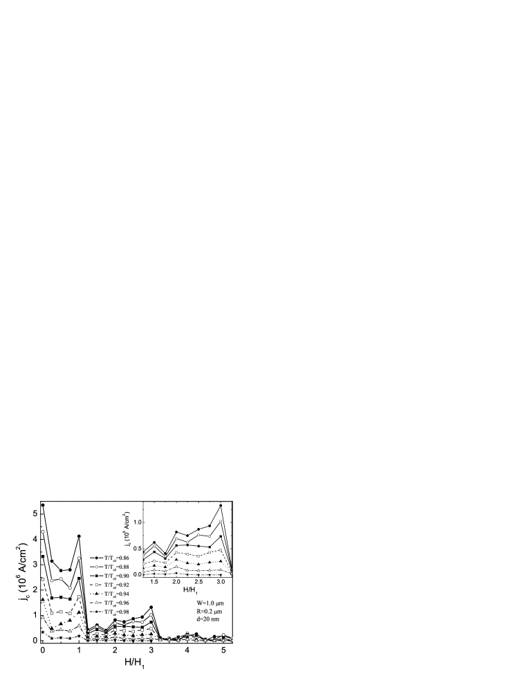
So far, we presented results at a fixed temperature. In what follows, we include temperature in our numerical analysis through the temperature dependence of the coherence length . We now consider the superconducting film with thickness nm, interhole distance m, and antidot radius m. We choose the coherence length nm and the penetration depth nm, which are typical values for Pb films. Fig. 17 shows the calculated critical current of the sample as a function of the applied field normalized to the first matching field at temperatures . As expected, decreasing the temperature leads to a larger critical current for all values of the applied field. The relative height of the peak at zero field with respect to one at the first matching field increases with increasing temperature [see Fig. 18(a)]). At higher temperatures, i.e. for , a certain suppression of the order parameter is present around the antidots [right inset in Fig. 18(a)] as the core of pinned vortices overlaps with the interstitial regions. Consequently, the suppressed order parameter leads to a smaller . The caging effect is found for temperatures [see Fig. 18(b)] and it disappears with temperature when approaching , since the vortices entirely cover the interstitial regions and effectively destroy superconductivity.

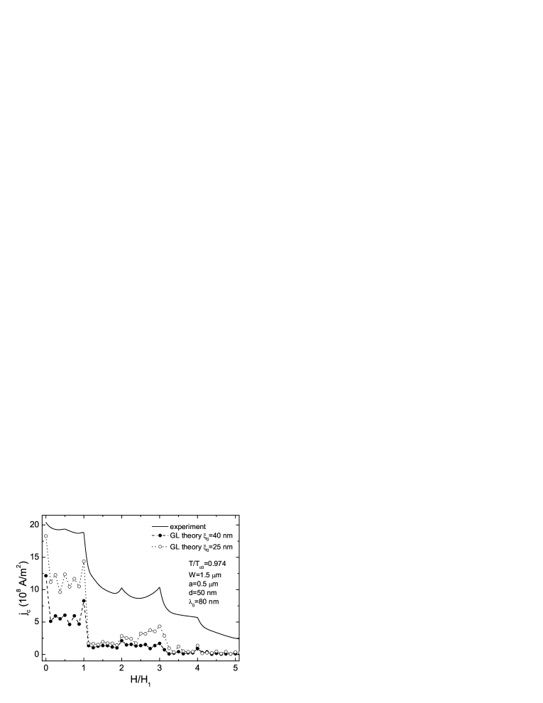
This effect that the critical current is larger for larger fields was recently observed experimentally. silha05 The considered sample was a Pb film of thickness 50nm, with square antidots of size m and period m. The coherence length and the penetration depth at zero temperature were estimated to be nm and nm. Although plotted for other purposes, Fig. 6(b) in Ref. silha05 demonstrates a clear overshoot of the critical current at with respect to the one at , at the temperature . Fig. 19 shows the comparison of the calculated critical current density (dots) with experiment (solid line). Our curve shows the same qualitative behavior as the experimental one, though a quantitative agreement is lacking for the experimentally estimated values of and . Better correspondence was achieved for smaller values of , indicating somewhat “dirty” sample in the experiment. No further attempts were made to improve the quantitative agreement with experiment because of the different determination of in the experiment and in our theory. In our calculations we use a dynamical criterium, i.e. we assume normal state as soon as vortices are set in motion, whereas in transport measurements a certain value of the threshold voltage was used to determine the critical current and the surface barrier at the edges is important. Therefore, our result should be considered as a lower limit to the experimental critical current. The qualitative behavior of at the matching fields should not be influenced by these facts.
VI Superconducting/normal phase boundary
The presence of antidot lattice in a superconducting film not only enhances the vortex-pinning, which was discussed in the previous section, but also affects substantially the nucleation of superconductivity. Due to the superconducting/vacuum interface at the antidots, surface superconductivity will be important around each antidot, at fields above the bulk critical field . This makes it possible to enhance the critical field in patterned superconducting films above and even beyond the third critical field . The ratio tends to the value , the enhancement factor for a semi-infinite slab. gennes However, for a dense antidot lattice a much larger enhancement can be achieved. Namely, if the antidots are sufficiently closely spaced, almost the entire sample may become superconducting at high fields through surface superconductivity.
The critical field of superconducting Pb films with a square array of antidots was investigated in Ref. HT by the magneto resistance measurements. The experimentally obtained phase boundary shows a cusp-like behavior with cusps at integer and some fractional matching fields. The amplitude of the cusps depend on the resistive criterion: the cusps become sharper and their amplitude increases with decreasing this criterion.
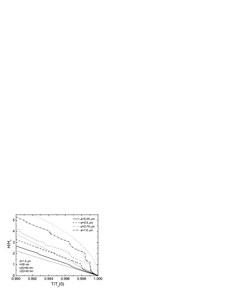
We investigated numerically the phase boundary for a superconducting film of thickness m in the presence of a regular array of square antidots with lattice period m. We take the coherence length at zero temperature as nm and penetration depth as nm. Fig. 20 shows the calculated phase diagram for different sizes of the antidots: m (solid curve), m (dashed curve), m (dotted curve), and m (dash-dotted curve). For comparative reasons, we plotted also the phase boundary for a plain film (thin solid curve) with the same coherence length nm, obtained from the well-known expression for the upper critical field
| (5) |
It can be easily seen that the antidot lattice has a profound influence on the critical magnetic field, as compared to a reference non-patterned film. The critical temperature is enhanced at every field, and vice versa, regardless of the size of the antidots. Note also that matching features are present in at integer matching fields. For small radius of the antidots matching peaks at higher integer matching fields are weakly pronounced, due to the small hole-saturation number (see Sec. III). We did not observe clear evidence of fractional matching features.
For small radius of the antidots the sample basically acts as a non-patterned film for temperatures close to and the dependence of the critical temperature on the applied field is almost linear. For larger sizes of the antidots (e.g. dotted and dash-dotted curves in Fig. 20), the critical field becomes substantially higher than the third critical field of a semi-infinite slab (thin dashed curve), and the peaks at matching fields are more pronounced. In addition, exhibits a parabolic background as for a thin slab in a perpendicular field, as well as to a thin film in a parallel field, which can be described in the London limit by tinkham
| (6) |
where stands for the width of the superconducting strip.
VII Conclusions
We have studied the vortex structure of a thin superconducting film with a regular array of antidots, which shows a rich variety of ordered vortex lattice configurations for different matching and fractional matching fields . For small radius of the holes, the vortex configurations with one vortex captured in each hole and the others located in the interstitial sites are realized, where interstitial vortices form regular patterns, either as multi- or giant vortices, or combination of giant- and multi-vortex states. For particular geometrical parameters of the sample and the applied field, a symmetry imposed vortex-antivortex configuration is found. Depending on the ratio between the hole radius and the interhole distance , multi-quanta vortices may be forced into the antidots, in spite of their low saturation number at smaller magnetic fields. To illustrate the transition between possible multi-quanta states in the holes we showed a diagram of the occupation number as a function of the radius of the holes and interhole distance for different values of the effective GL parameter. increases with decreasing due to the enhanced expulsion of the magnetic field from the superconductor and giant vortices become energetically favorable because of the attractive interaction between the vortices.
When the pinning force of the antidots is small, i.e. small radius of the antidots, the triangular vortex lattice becomes energetically favorable. Depending on the applied field all the vortices can be located between the antidots, or some of them are pinned by the antidots and some of them are located between the pinning centers. We calculated the phase diagram which shows the transition between the triangular and pinned square vortex lattices for two values of the applied field and GL parameter . We found that the results from the simple London theory for the phase diagram are different from our GL results for different applied fields. Moreover, we could not find triangular vortex structures for the fields and as a ground state.
The critical current of the sample shows well defined peaks at different matching and fractional matching fields, indicating that vortices are strongly pinned by antidots. However, the level of enhancement at particular magnetic field strongly depends on the antidot occupation number . For certain parameters of the sample, the critical current becomes larger at higher matching fields, contrary to conventional behavior.
We also studied the phase boundary of regularly perforated superconducting film. When an antidot array is present the critical temperature is enhanced compared to a non-patterned film and distinct cusps in the phase boundary are found for different matching fields, which is in agreement with the experimental. HT This behavior is in contrast to the Little-Parks little like structures found in finite size superconductors. golib The increase of the antidot size for given lattice period leads to the change of the background from linear to parabolic behavior except for near .
ACKNOWLEDGEMENTS
This work was supported by the Flemish Science Foundation (FWO-Vl), the Belgian Science Policy (IUAP), the JSPS-ESF NES program, and the ESF-AQDJJ network.
References
- (1) K. Harada, O. Kamimura, H. Kasai, T. Matsuda, A. Tonomura, and V.V Moshchalkov, Science 274, 1167 (1996).
- (2) M. Baert, V.V. Metlushko, R. Jonckheere, V.V. Moshchalkov, and Y. Bruynseraede, Phys. Rev. Lett. 74, 3269 (1995).
- (3) V.V. Moshchalkov, M. Baert, V.V. Metlushko, E. Rosseel, M.J. Van Bael, K. Temst, R. Jonckheere, and Y. Bruynseraede, Phys. Rev. B 54, 7385 (1996).
- (4) V.V. Moshchalkov, M. Baert, V.V. Metlushko, E. Rosseel, M.J. Van Bael, K. Temst, Y. Bruynseraede, and R. Jonckheere, Phys. Rev. B 57, 3615 (1998).
- (5) V. Metlushko, U. Welp, G.W. Crabtree, R. Osgood, S.D. Bader, L.E. DeLong, Zhao Zhang, S.R.J. Brueck, B. Ilic, K. Chung, and P. J. Hesketh, Phys. Rev. B 60, R12 585 (1999).
- (6) L. Van Look, B.Y. Zhu, R. Jonckheere, B.R. Zhao, Z.X. Zhao, and V.V. Moshchalkov, Phys. Rev. B 66, 214511 (2002).
- (7) A.V. Silhanek, S. Raedts, M. Lange, and V.V. Moshchalkov, Phys. Rev. B 67, 064502 (2003).
- (8) A.V. Silhanek, S. Raedts, M.J. Van Bael, and V.V. Moshchalkov, Phys. Rev. B 70, 054515 (2004).
- (9) A.V. Silhanek, L. Van Look, R. Jonckheere, B.Y. Zhu, S. Raedts, and V.V. Moshchalkov, Phys. Rev. B 72, 014507 (2005).
- (10) S. Raedts, A.V. Silhanek, M.J. Van Bael, and V.V. Moshchalkov, Phys. Rev. B 70, 024509 (2004).
- (11) A.N. Grigorenko, G.D. Howells, S.J. Bending, J. Bekaert, M,J, Van Bael, L. Van Look, V.V. Moshchalkov, Y. Bruynseraede, G. Borghs, I.I. Kaya, R.A. Stradling. Phys. Rev. B 63, 052504 (2001).
- (12) M.M. Doria and G.F. Zebende, Phys. Rev. B 66, 064519 (2002).
- (13) J.I. Martin, M. Velez, J. Nogues, and Ivan K. Schuller, Phys. Rev. Lett. 79, 1929 (1997).
- (14) J.I. Martin, M. Velez, A. Hoffmann, I.K. Schuller, and J.L. Vicent, Phys. Rev. Lett. 83, 1022 (1999).
- (15) M.V. Milošević and F.M. Peeters, Phys. Rev. Lett. 93, 267006 (2004).
- (16) A.A. Abrikosov, Zh. Eksp. Teor. Fiz. 32, 1442 (1957).
- (17) W.H. Kleiner, L.M. Roth, and S.H. Autler, Phys. Rev. A 133, 1226 (1964).
- (18) C. Reichhardt, J. Groth, C.J. Olson, Stuart B. Field, and Franco Nori, Phys. Rev. B 54, 16108 (1997).
- (19) C. Reichhardt, C.J. Olson, and Franco Nori, Phys. Rev. B 57, 7937 (1998).
- (20) C. Reichhardt, G.T. Zimanyi, and N. Gronbech-Jensen, Phys. Rev. B 64, 014501 (2001).
- (21) C. Reichhardt and N. Gronbech-Jensen, Phys. Rev. B 63, 054510 (2001).
- (22) B.Y. Zhu, F. Marchesoni, V.V. Moshchalkov, and F. Nori, Phys. Rev. B 68, 014514 (2003).
- (23) G. Karapetrov, J. Fedor, M. Iavarone, D. Rosenmann, and W.K. Kwok, Phys. Rev. Lett. 95, 167002 (2005).
- (24) H. Nordborg and V.M. Vinokur, Phys. Rev. B 62, 12408 (2000).
- (25) G.S. Mkrtchyan and V.V. Shmidt, Sov. Phys. JETP 34, 195 (1972).
- (26) M. Doria, S.C. de Andrade, and E. Sardella, Physica C 341-348, 1199 (2000).
- (27) A. Bezryadin and B. Pannetier, Physica Scripta. 66, 225 (1996).
- (28) A.I. Buzdin, Phys. Rev. B 47, 11416 (1993).
- (29) A. Bezryadin and B. Pannetier, J. Low Temp. Phys. 98, 251 (1995).
- (30) V.A. Schweigert, F.M. Peeters, and P.S. Deo, Phys. Rev. Lett. 81, 2783 (1998).
- (31) V.A. Schweigert and F.M. Peeters, Phys. Rev. B. 57, 13817 (1998).
- (32) M.M. Doria, J.E. Gubernatis, and D. Rainer, Phys. Rev. B 39, 9573 (1989).
- (33) R. Kato, Y. Enomoto, and S. Maekawa, Phys. Rev. B 47, 8016 (1993).
- (34) G.R. Berdiyorov, M.V. Milošević, and F.M. Peeters, Phys. Rev. Lett. 96, 207001 (2006).
- (35) G.R. Berdiyorov, M.V. Milošević, and F.M. Peeters, Physica C 437-438, 25 (2006).
- (36) M. Tinkham, Introduction to Superconductivity (New York: McGraw-Hill) (1996).
- (37) G. Stenuit, S. Michotte, J. Govaerts, and L. Piraux, Supercond. Sci. Technol. 18, 174 (2005).
- (38) P.G. de Gennes, Superconductivity of Metals and Alloys (Benjamin, New York, 1966).
- (39) W.V. Pogosov, A.L. Rakhmanov, and V.V. Moshchalkov, Phys. Rev. B 67, 014532 (2003).
- (40) G.R. Berdiyorov, M.V. Milošević, and F.M. Peeters, Europhysics Letters 74(3), 493 (2006).
- (41) E. Rosseel, T. Puig, M. Baert, M.J. Van Bael, V.V. Moshchalkov, and Y. Bruynseraede, Physica C 282-287, 1567 (1997).
- (42) W.A. Little and R. Parks, Phys. Rev. A 113, 97 (1964).
- (43) G.R. Berdiyorov, B.J. Baelus, M.V. Milošević, and F.M. Peeters, Phys. Rev. B 68, 174521 (2003).