An electron spin injection driven paramagnetic solid state MASER device
Abstract
In response to an external, microwave-frequency magnetic field, a paramagnetic medium will absorb energy from the field that drives the magnetization dynamics. Here we describe a new process by which an external spin injection source, when combined with the microwave field spin-pumping, can drive the paramagnetic medium from one that absorbs microwave energy to one that emits microwave energy. We derive a simple condition for the crossover from absorptive to emissive behavior. Based on this process, we propose a spin injection-driven paramagnetic MASER device.
In spin electronics (“spintronics”), the spin degree of freedom of the electron is used as a new means of storing, manipulating and transferring signals and information wolf . Since the prediction that a spin-polarized current can excite the (stimulated) emission of spin waves at a ferromagnetic interface berger , it has been demonstrated in magnetic multilayer systems that spin-polarized currents can drive microwave-frequency magnetization dynamics in the ferromagnetic layers tsoi ; kiselev ; rippard . More recently, it has been proposed that the magnetization dynamics of a ferromagnet can be used as a “spin pump” to drive a spin current into an adjacent, non-magnetic metallic layer brataas . In all of the above, the dynamics of the magnetization in the ferromagnetic layer is of primary importance.
We have recently shown, however, that a ferromagnet is not required for spin pumping, since applied radio-frequency (rf) magnetic fields can produce spin accumulation in paramagnetic materials watts . In this case, the paramagnetic medium absorbs energy from the external microwave magnetic field to produce the non-equilibrium spin accumulation. In this letter we describe a new effect in which the energy flow can be reversed: by combining an external spin injection source with microwave field spin pumping in a paramagnetic medium, the system can be driven from one that absorbs microwave energy to one that emits microwave energy. When the medium is placed within a resonant circuit, it is possible to obtain MASER (Microwave Amplification by Stimulated Emission of Radiation) action driven by spin injection.
The operation of a MASER device requires the generation of population inversion. In a two-level paramagnetic MASER system, both excitation and stimulated emission occur from the same pair of levels fain . Population inversion can be produced by separating the processes of excitation and emission in time, for instance by pulsed excitation. In multi-level systems the levels used for excitation and emission can be separated, and continuous operation is then possible fain . For example, a proton nuclear spin MASER was realized using the coupling between the nuclear and electron spins, and exciting the latter with microwaves abragam , or by optically pumping nuclear transitions in 3He robinson . The continuing progress in the field of spintronics in both technological advances as well as the understanding of fundamental processes, offers a new possibility in which a spin current injected into the paramagnetic medium can act as a continuous source of population inversion. As we will show, this allows for a straightforward description of MASER operation with semi-classical Bloch-type equations written in terms of spin accumulation. The proposed spin injection driven MASER, at least in its present form, is not a practical design for use in applications, but we show that it is feasible to fabricate and study one with the current level of technology, as demonstrated in, for instance, spin current switching experiments spincurrent and microwave pulsed field-induced ferromagnetic switching switching .
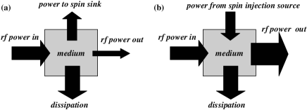
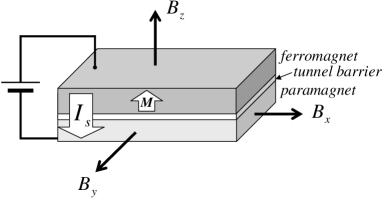
The principle behind the device is illustrated in Fig. 1. In Fig. 1a, part of the rf power incident on a paramagnetic medium is absorbed in the process of creating spin accumulation in the system. Power is lost to internal dissipation due to spin relaxation and to an external “spin sink.” In a real device this could be a ferromagnetic electrode used to probe the spin accumulation in the paramagnetic region. However, the role of the spin sink can be reversed by driving a spin-polarized current into the paramagnet from an externally-powered spin source, as shown in Fig. 1b. As we will demonstrate below, this allows the medium to exhibit rf power gain. Fig. 2 shows schematically a bilayer structure for injecting spins electrically: a ferromagnetic layer is deposited on top of the paramagnetic layer (separated by a thin aluminum oxide tunnel barrier), and the layers are connected to opposite terminals of a voltage source so that an electrical current is driven across the interface between the layers. This will cause a spin current to flow into the paramagnetic layer, whose thickness is assumed to be much less than its spin relaxation length so that a uniform spin accumulation will build up in the layer. The role of the ferromagnet in Fig. 2 is purely as a source of spin current. The dynamics of the magnetization or spin waves in the ferromagnet are not relevant to our description. We will first show how the injected spin current modifies the solutions for the spin-pumped spin accumulation in the medium, and then analyze the response of the system within an electrical circuit model.
In a previous publication watts , we have described the dynamics of the spin accumulation in response to a time-dependent magnetic field . We now extend this description to include interaction with an external spin source:
| (1) |
where is the injected spin current (in units of power, as described below), is the Larmor frequency ( is the electron g-factor), and is the spin relaxation time. Eq. 1 describes the time evolution of the spin accumulation in response to four physical processes (the four terms on the right-hand side of the equation): “spin pumping,” spin relaxation, spin precession, and spin injection. The spin pumping term describes the rate at which the time-dependent magnetic field, via the Zeeman energy, pushes spins aligned with the magnetic field below the Fermi level, and anti-aligned spins above the Fermi level, behaving essentially as a source of locally-injected, time-dependent spin currents watts . In a uniform, paramagnetic system, we previously found that for a magnetic field rotating with angular frequency in the x-y plane, a constant spin accumulation is generated in the z-direction. Eqn. 1 (with ) may be connected to electron spin resonance theory by observing that the time-dependent magnetization is given by , where is the total electron density of states at the Fermi level. The first term in the expression for describes the non-equilibrium magnetization, and the second term describes the equilibrium magnetization due to the field-induced paramagnetism whitfield ; abragam .
The system in Fig. 2 is now spin-pumped by applying a magnetic field that rotates in the x-y plane at microwave frequency , and a static field is applied in the z-direction; and are the Larmor frequencies associated with these fields. A constant spin current is injected into the system, where is the spin accumulation that would be present in the paramagnet in the absence of the applied field, and is collinear with . The sign of depends on the orientation of the magnetization (usually fixed by ) and the direction of charge current flow across the interface. The spin accumulation is found by solving Eq. 1 after transforming to a rotating reference frame in which the in-plane magnetic field is static watts . The solutions are:
| (2) | ||||
| (3) | ||||
| (4) |
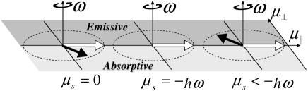
where and refer to the components of the spin accumulation that rotate in-phase (dispersive component) and out-of-phase (absorptive/emissive component) with the field , respectively. In our previous work we focused on , which can be measured electrically in a dc transport experiment by using ferromagnetic detection electrodes. Here, with the addition of the injected spin current, we instead focus on and . In Fig. 3 we illustrate three cases for specific values of . When , is always negative. This situation is shown in Fig. 3a, where the black vector is the in-plane spin accumulation in the rotating reference frame. The vector will always lie in the half-plane , which represents energy absorption from the field. When , we have that and , thus giving the remarkable result that the spin pumping effect can be turned off with an injected spin current. This is shown in Fig.3b, where the in-plane spin accumulation vector has disappeared. When , both and change sign as shown in Fig. 3c. The spin accumulation vector now lies in the half-plane , which represents energy emission to the field. In MASER (or laser) terminology, this corresponds to stimulated emission resulting in the medium exhibiting gain.
In other words: the injected spins, originally oriented along the z-direction, will precess around the field . Depending on their initial polarization in the z-direction, they will give either a positive or negative contribution to , and depending on the sign of , they will either enhance the damping or generate gain.
Using Eqs. 2-4 we find the power per unit volume in the paramagnet dissipated due to spin relaxation:
| (5) |
The net power extracted from or supplied to the field is determined by the time-averaged value of landau :
| (6) |
This power can be positive or negative, as discussed above. The power supplied from the external spin source is
| (7) |
, as required by conservation of energy powernote .
While it is possible to generate locally rotating rf magnetic fields in a device, it is generally more practical to use a linear rf driving field in resonance with , similar to conventional elecron spin resonance experiments. A linear field can be decomposed into two counter-rotating magnetic fields of half the magnitude. For positive , only the field rotating counter-clockwise has the right sense for the resonant condition to hold, and thus to contribute significantly to the response. We have checked this explicitly for the relevant range of parameters with exact, numerical solutions of Eq. 1. To simplify the expressions that follow, we will therefore assume the resonant condition with the convention of positive , and further assume that , which is typically the case experimentally. We then have and . The in-plane magnetization components and are now both linear in , and we can define a linear, complex magnetic susceptibility for . Then the components of the susceptibility are:
| (8) | ||||
| (9) |
where is a constant determined by the material parameters and .
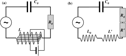
In order to analyze the performance of our system within a device, we model the system as the LRC circuit shown in Fig. 4. We follow a standard treatment for spin resonance theory abragam ; yukalov . The inductor coil is used to both excite and detect the magnetization induced in the medium. The inductance is modified by as , where is the filling factor of the medium in the coil fillingfactor . The total impedance of the circuit is now given by
| (10) | ||||
contributes to an additional resistance in the circuit, which can be positive or negative. With , will always be negative (absorptive) and therefore so will . is then positive and always increases the damping in the circuit. But with , both and are positive, and is therefore negative. The reduction in the damping can be measured as a change in the transmitted power in a suitably designed waveguide structure grundler . Self-sustaining, MASER oscillations vanderPol are obtained when the magnitude of the negative is larger than , leading to negative effective resistance in the circuit. We can write the condition in terms of the quality factor of the unloaded circuit:
| (11) |
Using typical parameters for Al with of order s at room temperature, we find that the product is of order 1/eV. Thus, for we have, effectively, . To find a value for we then only need to estimate . Spin relaxation in a confined medium can be described as an effective resistance between parallel spin up and spin down channels. For injection into an Al metal island ( nm3), a spin resistance of 10 was found experimentally zaffalon . Scaling to a larger medium m3, the spin resistance is reduced to about 1 . Assuming a ferromagnet polarization of 50% and a tunnel barrier resistance of 1 k (about the lowest value that can be obtained technologically) that limits the charge current to 10 mA, with which a spin accumulation voltage of order 5 meV should be achievable (this is indeed much greater than for microwave frequencies up to tens of GHz). Thus we estimate that should be greater than 200. Although this is a relatively large , it should be possible to fabricate such an on-chip resonator, especially in a proof-of-principle experiment in which superconducting strip lines are used to construct the resonant circuit superconductor . Other sources of dissipation should also be considered, such as eddy-current damping. The planar, thin-film structure shown in Fig. 2 has the advantage that the fields and oscillate in the film plane, thus reducing the importance of this effect.
To estimate the typical microwave power which can be emitted by this device, we assume that the amplitude of the oscillating is limited by the condition , at which point the stimulated emission becomes less efficient (Eqs. 3 and 6). From Eq. 6 we then find that a typical power is 1 W (note, however, that this scales with the device dimensions). The total power supplied by the voltage source is of order 100 mW. The main reason for this low efficiency is the mismatch between the resistance of the tunnel barrier (1 k) and the typical “spin resistance” (1 ) of the system. This is purely a technological problem related to the limitations of using aluminum oxide tunnel barriers.
In conclusion, we have shown that by combining an external spin injection source with microwave field spin pumping on a paramagnetic medium, it can be made to exhibit microwave energy gain for sufficiently large injected spin currents. This effect does not depend on the details of the paramagnet or the spin injection source. While we have used a simple metallic multilayer system to illustrate our proposal for a spin-injection MASER, our description can be readily applied to other systems, such as semiconductors, and other sources of spin injection, such as optical pumping.
We acknowledge useful discussions with C. H. van der Wal and W. van Roy. Support for this work has been provided by the Stichting Fundamenteel Onderzoek der Materie (FOM).
References
- (1) S. A. Wolf, D. D. Awschalom, R. A. Buhrman, J. M. Daughton, S. von Molnár, M. L. Roukes, A. Y. Chtchelkanova, and D. M. Treger, Science 294, 1488 (2001).
- (2) L. Berger, Phys. Rev. B 54, 9353 (1996).
- (3) M. Tsoi, A. G. M. Jansen, J. Bass, W.-C. Chiang, V. Tsoi and P. Wyder, Nature 406, 46 (2000).
- (4) S. I. Kiselev, J. C. Sankey, I. N. Krivorotov, N. C. Emley, R. J. Schoelkopf, R. A. Buhrman and D. C. Ralph, Nature 425, 380 (2003).
- (5) W. H. Rippard, M. R. Pufall, S. Kaka, S. E. Russek, and T. J. Silva, Phys. Rev. Lett. 92, 027201 (2004).
- (6) A. Brataas, Y. Tserkovnyak, G. E. W. Bauer, and B. I. Halperin, Phys. Rev. B 66, 060404(R) (2002).
- (7) S. M. Watts, J. Grollier, C. H. van der Wal, and B. J. van Wees, Phys. Rev. Lett. 96, 077201 (2006).
- (8) V. M. Fain and Ya. I. Khanin, Quantum Electronics Vol. 2 (1969).
- (9) A. Abragam, The Principles of Nuclear Magnetism (1961).
- (10) H. G. Robinson and T. Myint, Appl. Phys. Lett. 5, 116 (1964).
- (11) E.B. Myers, D.C. Ralph, J.A. Katine, R.N. Louie, and R.A. Buhrman, Science 285, 867 (1999); J.A. Katine, F.J. Albert, R.A. Buhrman, E.B. Myers, and D.C. Ralph, Phys. Rev. Lett. 84, 3149 (2000).
- (12) Th. Gerrits, H. A. M. van den Berg, J. Hohlfeld, L. Bär, and Th. Rasing, Nature 418, 509 (2002); H.W. Schumacher, C. Chappert, P. Crozat, R. C. Sousa, P. P. Freitas, J. Miltat, J. Fassbender, and B. Hillebrands, Phys. Rev. Lett. 90, 017201 (2003).
- (13) G. Whitfield and A. G. Redfield, Phys. Rev. 106, 918 (1957).
- (14) L. D. Landau and E. M. Lifshitz, Electrodynamics of Continuous Media (1960).
- (15) In addition to these power flows related to the spin degree of freedom, the external voltage source also injects a substantial amount of power unrelated to spin. This will be dissipated as heat, and will not affect the system.
- (16) A more detailed treatment of the coupling between a spin sample and the resonator can be found in V. I. Yukalov, Laser Physics 5, 970 (1995).
- (17) We will assume is of order 1. An integral expression for the filling factor is given by N. Bloembergen and R. V. Pound, Phys. Rev. 95, 8 (1954).
- (18) E.g., see F. Giesen, J. Podbielski, T. Korn, and D. Grundler, J. Appl. Phys. 97, 10A712 (2005).
- (19) Negative resistance oscillators are usually referred to as van der Pol oscillators, see B. van der Pol, Phil. Mag. Series 7, 3, 65 (1927).
- (20) M. Zaffalon and B. J. van Wees, Phys. Rev. Lett. 91, 186601 (2003).
- (21) A. Wallraff, D. Schuster, A. Blais, L. Frunzio, R.-S. Huang, J. Majer, S. Kumar, S. M. Girvin, and R. J. Schoelkopf, cond-mat/0407325.