Collapse of Double-Walled Carbon Nanotube Bundles under Hydrostatic Pressure
Abstract
We use classical molecular dynamics simulations to study the collapse of single (SWNT) and double-walled (DWNT) carbon nanotube bundles under hydrostatic pressure. The collapse pressure () varies as , where is the SWNT radius or the DWNT effective radius. The bundles show 30 % hysteresis and the hexagonally close packed lattice is completely restored on decompression. The of DWNT is found to be close to the sum of its values for the inner and the outer tubes considered separately as SWNT, demonstrating that the inner tube supports the outer tube and that the effective bending stiffness of DWNT, . We use an elastica formulation to derive the scaling and the collapse behavior of DWNT and multi-walled carbon nanotubes.
pacs:
81.07.De, 02.70.Ns, 62.20.Dc, 62.50.+pI Introduction
Since their discovery, carbon nanotubes have been subject to intense theoretical and experimental investigations due to their fascinating structural, electronic, and mechanical properties Saito1998 . Carbon nanotubes are showing great promise in such diverse fields as nanoelectronics, actuators, sensors Ghosh2003 , nanofluidics, hydrogen storage, and high-strength materials. The mechanical properties of carbon nanotubes depend on the number of coaxial graphitic rings that go into their making. Significant advances have been made in the understanding of single (SWNT) and multi-walled (MWNT) carbon nanotubes. Double-walled carbon nanotubes (DWNT) have been observed and synthesized Smith1998 ; Bandow2001 more recently. Being the simplest of the MWNT, they are ideal systems to study the evolution of various properties from the single to the multi-walled regime.
High-pressure Raman experiments on SWNT bundles Venkateswaran1999 ; Peters2000 ; Sandler2003 point to a structural phase transition at GPa. The current understanding is that the initially circular nanotube cross section is distorted to an oval shape under pressure. High pressure X-ray diffraction studies also indicate a phase transition Sharma2001 from the ambient triangular lattice symmetry, which reappears under decompression. Molecular dynamics simulations suggest that SWNT bundles Elliot2004 ; Zhang2004 as well as isolated tubes Capaz2004 ; Sun2004 collapse under hydrostatic pressure and that the collapse pressure varies as an inverse power law of the tube radius. More recently, several workers Pfeiffer2003 ; Arvanitidis2005 ; Puech2004 ; Puech2004a ; Venkateswaran2004 have used Raman spectroscopy to study bundles of DWNT under hydrostatic pressure. They conclude that the environment inside the outer tube is highly defect free and unperturbed, that the outer tube acts as a protective shield for the inner tube and that the inner tube provides structural support to the outer tube.
In this paper, we describe a set of molecular dynamics simulations performed to investigate the behavior of DWNT under pressure, focusing on the response of the inner and the outer tubes. These results are contrasted with similar MD simulations on bundles of SWNT. Observed results are interpreted within the framework of the elastica theory.
II Simulation Methodology
We have used DREIDING Mayo1990 , a standard generic macromolecular force field, in all our molecular dynamics (MD) simulations. Table 1 lists the force field parameters used to calculate intra and inter molecular interactions. Elliott et al. Elliot2004 have successfully used this force field to study the collapse of SWNT bundles under hydrostatic pressure. Our simulations have been performed using ModulaSim Modulasim , a modular and general purpose molecular modeling package. The ensemble used was one of constant particle number, pressure, and temperature (NPT). The temperature (300 K) and the applied hydrostatic pressure were maintained using the Berendsen thermostat and barostat Berendsen1984 . The simulation cell consisted of 16 independent SWNT or DWNT arranged in a hexagonally close packed 4 4 bundle, with periodic boundary conditions and pressure applied along all three mutually perpendicular directions. The tubes were ten unit cells long (2.3 nm). It has been found Elliot2004 that nine independent tubes, ten unit cells long, are sufficient to avoid finite size effects. The MD simulations were carried out on four SWNT, (5,5), (10,10), (15,15), and (20,20) and four DWNT, (5,5)@(10,10), (7,7)@(12,12), (10,10)@(15,15), and (15,15)@(20,20) bundles using the standard velocity Verlet algorithm to integrate the equations of motion. The gap between the inner and the outer tubes is 3.4 , close to the inter-layer gap in graphite. The bundles were initially equilibrated at atmospheric pressure and subsequently subjected to step-wise monotonically increasing hydrostatic pressure increments, allowing the unit cell volume to equilibrate for at least 10 ps at each step. The simulation time step was 1 fs. Information about the structural transition was obtained by measuring the unit cell volume after equilibration at each hydrostatic pressure step.
III Results and Discussion
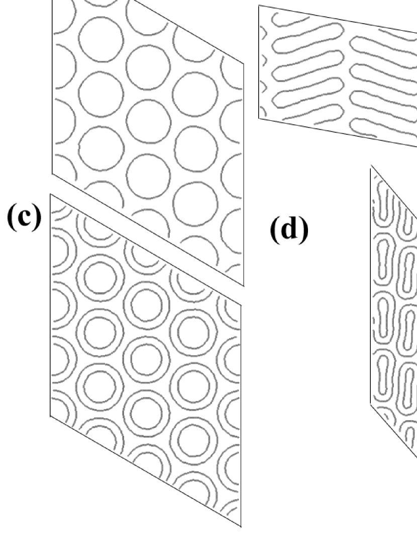
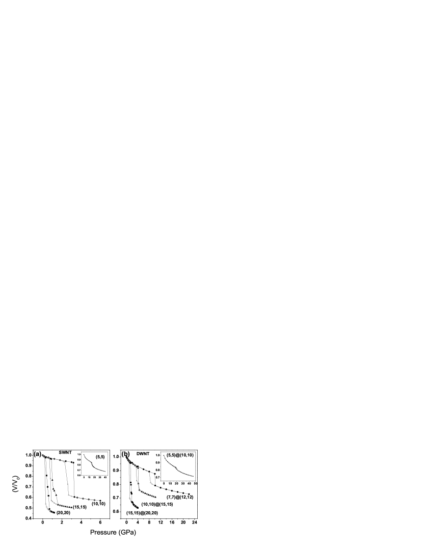
All the SWNT and DWNT equilibrated at atmospheric pressure have nearly circular cross sections, as shown in Figs. 1(a) and (c) for a SWNT and a DWNT bundle, respectively. At atmospheric pressure, where and are the smallest and the largest distances from the center to the circumference of the tube cross section. To study the structural transition, we plot the reduced volume (), where is the unit cell volume at atmospheric pressure, for the various SWNT bundles as a function of pressure as shown in Fig. 2 (a). It is clear that each of the four SWNT bundles undergoes a spontaneous structural transition at a critical pressure (), which decreases as the radius of the tubes increases, in agreement with previously published results Elliot2004 ; Zhang2004 . Unless otherwise specified, refers to the structural change pressure on the loading curve. On plotting the reduced volume versus pressure for the DWNT bundles, as shown in Fig. 2 (b), we once again observe clear structural transitions at well-defined critical pressures. Up to the critical pressure, the tube cross sections remain nearly circular with slight deformations from the circular shape. When the applied hydrostatic pressure exceeds , the tube cross sections assume an elliptical shape. Further increase in pressure results in a dumbbell shape as shown in Figs. 1(b) and (d). The loading and unloading curves show a 30% hysteresis in all the bundles studied. The hysteresis is calculated as . The hexagonally close packed lattice is completely restored in all SWNT and DWNT bundles on decompression. A closer look at the critical pressures of the DWNT bundles in Fig. 2 (b) reveals several interesting features. First, we notice that the of a DWNT bundle is greater than the of an SWNT bundle of the outer tubes alone. For example, the of the (10,10)@(15,15) DWNT is 4.1 GPa, a value higher as compared to the of (15,15) SWNT (0.9 GPa). This shows that the inner tube supports the outer tube under hydrostatic pressure. Second, the of the DWNT bundle is even higher than the of an SWNT bundle of the inner tubes alone. For the (10,10)@(15,15) tubes, 4.1 GPa ( of the DWNT bundle) is higher than 3.2 GPa ( of (10,10) SWNT bundle). Having demonstrated that the of a DWNT bundle is higher than the of both the inner and the outer tubes, we now ask whether one can predict the of a DWNT bundle with the knowledge of the of the inner and the outer tubes. From Fig. 2, we see that the of a DWNT bundle is close to the sum of the of the inner and the outer tubes. In our example, 4.1 GPa ( of the (10,10)@(15,15) DWNT bundle) is equal to 3.2 GPa ( of (10,10) SWNT bundle) plus 0.9 GPa ( of (15,15) SWNT bundle). In section IV, we derive an analytical result that demonstrates this behavior.
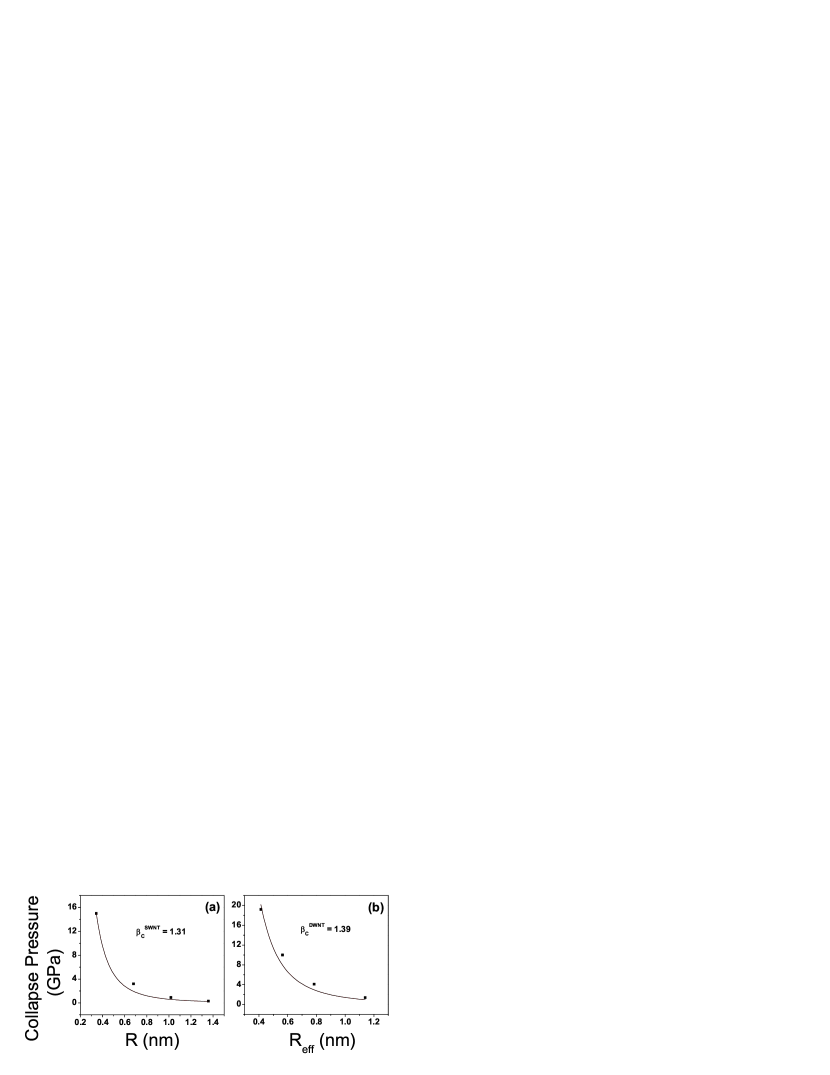
Fig. 3 (a) shows the collapse pressure of the SWNT bundles versus the tube radius along with a fit Capaz2004 ; Sun2004 . If we now define an effective radius of a MWNT with walls, as , the collapse pressure of the DWNT bundles is found to follow a dependence as seen from Fig. 3 (b). Let be the bending modulus of the graphene sheet so that the energy per unit surface area associated with curvature is given by yakobson1 ; Pantano2004 ; Tang_2cyl ; Tang2005 . The value of has been estimated from a plot of the single point energies per unit surface area of seven isolated SWNT as a function of (Fig. 4 (a)), which gives the value of to be 2.90 eV. The mean curvature for a bundle was calculated by averaging its local value at each atom of each tube (see Appendix). Using the values of curvature and (from Fig. 4), the values of the elastic energy per unit surface area for all the bundles were calculated and are plotted as a function of pressure in Fig. 5. It is clear that the elastic energy, as expected, follows the structural transition shown in Fig. 2. The insets show that the relative increase in elastic energy during collapse increases linearly with radius for both SWNT and DWNT, which can be understood by the following argument. The elastic energy per unit length of a nanotube of radius before collapse is . After collapse, the tube has flat regions, which have no elastic energy, and bent regions. The shape of the bent regions is invariant with respect to change in radius . That is, any increase in simply increases the flat regions. Let be an effective radius of the bent regions. Then, the elastic energy of the collapsed nanotube is . Since is a fixed number that is independent of (but less than in magnitude), the relative increase in elastic energy on collapse is
| (1) |
This shows that the percent change in elastic energy on collapse depends linearly on the radius of the nanotubes.
IV Scaling of the response with radius, adhesion energy, and bending elasticity.
The main results so far, dependence of and that the for is a sum of the for packing of separate SWNT bundles, can be derived from a formulation based on elastica theory timoshenko ; Frisch-Fay1962 . Assume that the response of nanotube bundles to external loading can be calculated by minimizing a properly defined potential energy functional Tang_2cyl ; Tang2005 . For a nanotube bundle of length , assume that deformations are primarily two-dimensional in the cross section of the bundle. Let denote length along a path that traverses the graphene sheets in this 2D cross section. Let represent the complete path and the part of this path on which we apply external pressure. Tubes interact with each other via an interatomic potential that has an attractive van der Waals component and a short-range repulsion. The latter component of the interaction effectively prohibits two surfaces from approaching each other too closely. Therefore, the surface can be considered as consisting of two parts. Over the part of where the short-range repulsion creates a flat interface, , we say they are in contact; over the remaining surface, , we say that they are not in contact. The utility of this partitioning is that a material property, the work of adhesion of two graphene sheets, can be associated with . The potential energy per unit length of the bundle can be written as Tang_2cyl ; Tang2005
| (2) |
where the first term represents energy due to bending of the graphene sheet to mean curvature , the second and third terms capture adhesive van der Waals interactions, the fourth term represents the work of external forces with , the external traction, and , the displacement on the surface where tractions are applied, and the last term is the energy of formation of a flat sheet ( is the energy of formation per unit surface area of a graphene sheet). The attractive van der Waals energy has been written in two parts. The first, , captures regions where graphene sheets are in contact; is the work of adhesion per unit area of bringing two flat nanotube walls from infinity to equilibrium separation. For DWNT and MWNT, there is a contribution to the work of adhesion due to interlayer contact. Because layers deform together, this contribution does not change with deformation. It will therefore vanish in a variation and for DWNT/MWNT can be identified as the area of contact between outermost layers. The term represents interactions outside the contacting regions. Once the tubes are in contact, the change in this term with further deformation can be neglected Tang_2cyl ; Tang2005 . The scaling of the solution can be extracted simply by a suitable normalization. Normalizing all length scales in Eq. 2 by the radius, and dropping terms that vanish in a variation, we obtain an expression for potential energy per unit length, ,
| (3) |
where is a dimensionless applied traction field, is its (scalar) value for the case of fixed applied pressure, and is the unit normal. Our dimensionless formulation implicitly assumes that no other length scale enters into the problem, for example, through boundary conditions. A possible exception is the interlayer spacing. Prior to collapse, it has been shown that the deformation of two nanotubes in contact is independent of this parameterTang_2cyl ; Tang2005 . In the collapsed state the interlayer spacing perturbs only slightly the solution obtained by neglecting itTang_2cyl ; Tang2005 . On this basis, we neglect its influence on our formulation; this assumption is justified by good agreement between the predicted scaling and simulation results.
Therefore, within our assumptions, the deformation depends only on two dimensionless parameters, and . If the dominant influence on deformation is external pressure, then events such as collapse or phase transitions will occur at critical values of , say at . This establishes the scaling of critical pressure to be . In the absence of external pressure such events will occur at critical values of , as already established Tang_2cyl ; Tang2005 .
For commensurately packed MWNT, where difference in radius equals the equilibrium separation between graphene sheets, this argument can be extended to DWNT and MWNT. First, we recognize that the shape of any one shell in a deformed MWNT can be obtained from the shape of another shell simply by a change of scale. To build up a deformed MWNT packing, we therefore first start with a SWNT packing, say the shell with the largest diameter. Consider Fig. 1 (a), a SWNT bundle, in the case of deformations dominated by external pressure. At any stage of the deformation the solution is a function of . Denote by the surface tractions needed to support the shape of this shell. Now make an identical copy of the deformed bundle and reduce its diameter by a change in scale to a value just small enough to fit inside the first shell. The new shape is also a solution if we scale all the tractions according to . Take the smaller bundle, separate the nanotubes, and insert each into its corresponding tube in the larger bundle. If we assume that the interface between the walls of a DWNT cannot carry any shear tractions, the resulting bundle is also a solution. We note that the tractions on the inner tube have to be provided by the outer tube. This leads to the conclusion that the net external tractions we need to apply to the outer shell is the sum of tractions needed to bring the two constituent SWNT’s to similar shapes. This is easily generalized to a MWNT, establishing the fact that for deformation to the same normalized shape, the needed applied pressure is . All the nanotubes will collapse simultaneously and so
| (4) |
thus establishing the result that the collapse pressure for a MWNT packing is the sum of collapse pressures of the constituent SWNT packings, and providing the rationale for the effective radius defined earlier.
As an independent test of this model, we have plotted the collapse pressure as a function of in Fig. 3 (b); it fits a relationship well. The fit yields a value for eV. If we define the surface of DWNT to be a cylinder with radius , the energy per unit surface area of DWNT is given by
| (5) | |||||
where , is the radius of the inner tube, and is the radius of the outer tube. In Eq. 5, the first term corresponds to the elastic energies of the inner and outer tubes, the second term to the interaction energy of the two tubes and the third term to the energy of formation of the two tubes. Eq. 5 shows that the energy per unit surface area of DWNT scales with the inverse square of the length . This quantity is readily computed for different DWNT and Fig. 4(b) plots the single point energy per unit surface area of five DWNT as a function of . A fit using Tang_2cyl ; Tang2005 and yields a value of eV, which is close to twice . Together with the fit to collapse pressure, the data yield a value of , very close in value to the that obtained from simulations ().
V Summary
To summarize, we use classical MD simulations to show that DWNT bundles collapse at a critical pressure that, like in the case of SWNT, varies as , where is a suitably defined effective radius. We find that the SWNT and DWNT bundles show a 30% hysteresis and that the hexagonally close packed lattice is completely restored in all SWNT and DWNT bundles on decompression. Interestingly, we find that the of a DWNT bundle varies as the sum of the of the inner and the outer tubes considered separately as SWNT bundles (a result we derive analytically), demonstrating that the inner tube supports the outer tube and that , where is a bending stiffness.
ACKNOWLEDGEMENTS
AKS thanks the Department of Science and Technology, Govt. of India, for financial support. AJ’s initial contribution to this work was made during a stay at the Indian Institute of Science in 2005 as DuPont Chair. He would like to acknowledge the DuPont company for their support. VG thanks the Centre for High Energy Physics, Indian Institute of Science, for computational facilities and Dr. Sachindeo Vaidya and Dr. Tarun Deep Saini for useful discussions.
Note. After the completion of our analysis, Ye et al. Ye2005 published constant pressure MD simulations demonstrating a hydrostatic pressure-induced structural transition for isolated DWNT. The values of the critical pressures they obtain for isolated DWNT are 0.4 to 0.5 times the values we find for the same diameter DWNT arranged in a bundle.
APPENDIX: Calculation of mean curvatures for SWNT and DWNT bundles
The following algorithm was used for the calculation of the mean curvature for a bundle of SWNT or DWNT. Each of the 16 tubes in the system is an armchair tube with ten unit cells. It can be shown that the total number of atoms per tube is . The local curvature is calculated at every atom that belongs to the middle eight unit cells ( atoms). The atoms belonging to the unit cells at the ends of the tubes are not considered because these atoms do not have the sufficient number of neighbors required for our calculations (as will be clear later).
Each of the atoms is considered one at a time. For each atom, the coordinates of its three nearest neighbors and six next nearest neighbors are found using a search algorithm. The central atom’s three nearest neighbors are used to define a plane passing through them and the normal to this plane is found. This is defined to be the new z-axis. The new x- and y-axes are suitably defined to be mutually perpendicular.
A rotation matrix is now constructed using the components of the normal. The matrix is then used to transform the coordinates of the ten atoms (the central atom and its nine neighbors) to the new coordinate system. In the new coordinate system, a quadratic surface of the form is fit to the ten points as follows. The expanded form of the equation is given by . This equation can be written treating as the unknowns and as the coefficients. The coordinates of the ten points give us ten equations in six unknowns. In matrix notation, we have , where is the matrix to be determined. The values of are obtained by calculating using the relation .
The mean curvature of a surface, as defined above, is given by Dubrovin1992
| (6) |
The value of at the central atom is now calculated using the values of and the coordinates of the central atom.
This process is repeated for all the atoms of the tube. The local curvature values at atoms of the other fifteen tubes in the bundle are similarly calculated to yield a total of values. The average curvature for the bundle is simply the mean of these values. For bundles of DWNT, the same procedure is used, treating the inner and the outer tubes as separate SWNT and averaging over atoms in 32 tubes.
This method gave good results for all tubes except the very small (5,5) tube, which cannot be well approximated by a smooth cylinder even at 0 K. The calculated mean curvature, using the method described above, for an optimized (5,5) tube at 0 K differs from the value of the curvature of a cylinder of the same radius (given by ) by more than 5 %.
References
- (1) R. Saito, G. Dresselhaus, and M. S. Dresselhaus, Physical Properties of Carbon Nanotubes (Imperial College Press, London, 1998).
- (2) S. Ghosh, A. K. Sood, and N. Kumar, Science 299, 1042 (2003).
- (3) B. W. Smith, M. Monthioux, and D. E. Luzzi, Nature (London) 396, 323 (1998).
- (4) S. Bandow, M. Takizawa, K. Hirahara, and M. Yudasaka, Chem. Phys. Lett. 337, 48 (2001).
- (5) U. D. Venkateswaran, A. M. Rao, E. Richter, M. Menon, A. Rinzler, R. E. Smalley, and P. C. Eklund, Phys. Rev. B 59, 10928 (1999).
- (6) M. J. Peters, L. E. McNeil, J. P. Lu, and D. Kahn, Phys. Rev. B 61, 5939 (2000).
- (7) J. Sandler, M. S. P. Shaffer, A. H. Windle, and M. P. Halsall, Phys. Rev. B 67, 035417 (2003).
- (8) S. M. Sharma, S. Karmakar, S. K. Sikka, P. V. Teredesai, A. K. Sood, A. Govindaraj, and C. N. R. Rao, Phys. Rev. B 63, 205417 (2001).
- (9) J. A. Elliott, J. K. W. Sandler, A. H. Windle, R. J. Young, and M. S. P. Shaffer, Phys. Rev. Lett 92, 095501 (2004).
- (10) X. H. Zhang, D. Y. Sun, Z. F. Liu, and X. G. Gong, Phys. Rev. B 70, 035422 (2004).
- (11) R. B. Capaz, C. D. Spataru, P. Tangney, M. L. Cohen, and S. G. Louie, Phys. Stat. Sol. (b) 241, 3352 (2004).
- (12) D. Y. Sun, D. J. Shu, M. Ji, Feng Liu, M. Wang, X. G. Gong, Phys. Rev. B 70, 165417 (2004).
- (13) R. Pfeiffer, H. Kuzmany, Ch. Kramberger, Ch. Schaman, T. Pichler, H. Kataura, Y. Achiba, J. Kü rti, and V. Zólyomi, Phys. Rev. Lett. 90, 225501 (2005).
- (14) J. Arvanitidis, D. Christofilos, K. Papagelis, K. S. Andrikopoulos, T. Takenobu, Y. Iwasa, H. Kataura, S. Ves, and G. A. Kourouklis, Phys. Rev. B 71, 125404 (2005).
- (15) P. Puech, H. Hubel, D. J. Dunstan, R. R. Bacsa, C. Laurent, and W. S. Bacsa, Phys. Rev. Lett. 93, 095506 (2004).
- (16) P. Puech, H. Hubel, D. J. Dunstan, A. Bassil, R. Bacsa, A. Peigney, and E. Flahaut, Phys. Stat. Sol. (b) 241, 3360 (2004).
- (17) U. D. Venkateswaran, Phys. Stat. Sol. (b) 241, 3345 (2004).
- (18) S. L. Mayo, B. D. Olafson, and W. A. Goddard III, J. Phys. Chem. 94, 8897 (1990).
- (19) ModulaSim was originally developed at the Material and Process Simulation Center, California Institute of Technology, CA, USA. http://ruby.wag.caltech.edu/Projects/ModulaSim/index.html. It is now actively being developed at the University of Tours (YL), IISc, Bangalore (PKM), and University of Colorado, Boulder (Matthew A. Glaser).
- (20) H. J. C. Berendsen, J. P. M. Postma, W. F. van Gunsteren, A. DiNola, and J. R. Haak, J. Chem. Phys. 81, 3684 (1984).
- (21) B. Yakobson, C. Brabec, and J. Bernholc, Phys. Rev. Lett. 76, 2511 (1996).
- (22) A. Pantano, D. M. Parkes, and M. C. Boyce, J. Mech. Phys. Solids 52, 789 (2004).
- (23) T. Tang, A. Jagota, and C-Y Hui, J. Appl. Phys. 97, 074304 (2005).
- (24) T. Tang, A. Jagota, C-Y. Hui, N. J. Glassmaker, J. Appl. Phys. 97, 074310 (2005).
- (25) S. Timoshenko and S. Woinowsky-Krieger, Theory of Plates and Shells, 2nd ed. (McGraw-Hill, New York, 1959).
- (26) R. Frisch-Fay, Flexible Bars (Butterworths, Washington D.C., 1962).
- (27) X. Ye, D. Y. Sun, and X. G. Gong, Phys. Rev. B 72, 035454 (2005).
- (28) B. A. Dubrovin, A. T. Fomenko, and S. P. Novikov, Modern Geometry - Methods and Applications Part 1. The Geometry of Surfaces, Transformation Groups, and Fields (Springer Verlag, New York, 1992).
| 1.39 | 1050 (kcal/mol)/ | |||||
| 120∘ | 100 (kcal/mol)/rad2 | |||||
| 180∘ | 25.0 kcal/mol | 2 | ||||
| 0∘ | 40 (kcal/mol)/rad2 | |||||
| 3.8983 | 0.0951 kcal/mol |